EP1400374A2 - Runflat tire having crown-reinforcing insert extending into the sidewalls - Google Patents
Runflat tire having crown-reinforcing insert extending into the sidewalls Download PDFInfo
- Publication number
- EP1400374A2 EP1400374A2 EP03103388A EP03103388A EP1400374A2 EP 1400374 A2 EP1400374 A2 EP 1400374A2 EP 03103388 A EP03103388 A EP 03103388A EP 03103388 A EP03103388 A EP 03103388A EP 1400374 A2 EP1400374 A2 EP 1400374A2
- Authority
- EP
- European Patent Office
- Prior art keywords
- tire
- sidewall
- reinforcing
- crown
- ply
- Prior art date
- Legal status (The legal status is an assumption and is not a legal conclusion. Google has not performed a legal analysis and makes no representation as to the accuracy of the status listed.)
- Granted
Links
Images
Classifications
-
- B—PERFORMING OPERATIONS; TRANSPORTING
- B60—VEHICLES IN GENERAL
- B60C—VEHICLE TYRES; TYRE INFLATION; TYRE CHANGING; CONNECTING VALVES TO INFLATABLE ELASTIC BODIES IN GENERAL; DEVICES OR ARRANGEMENTS RELATED TO TYRES
- B60C15/00—Tyre beads, e.g. ply turn-up or overlap
- B60C15/0009—Tyre beads, e.g. ply turn-up or overlap features of the carcass terminal portion
- B60C15/0036—Tyre beads, e.g. ply turn-up or overlap features of the carcass terminal portion with high ply turn-up, i.e. folded around the bead core and terminating radially above the point of maximum section width
-
- B—PERFORMING OPERATIONS; TRANSPORTING
- B60—VEHICLES IN GENERAL
- B60C—VEHICLE TYRES; TYRE INFLATION; TYRE CHANGING; CONNECTING VALVES TO INFLATABLE ELASTIC BODIES IN GENERAL; DEVICES OR ARRANGEMENTS RELATED TO TYRES
- B60C15/00—Tyre beads, e.g. ply turn-up or overlap
- B60C15/0009—Tyre beads, e.g. ply turn-up or overlap features of the carcass terminal portion
- B60C15/0027—Tyre beads, e.g. ply turn-up or overlap features of the carcass terminal portion with low ply turn-up, i.e. folded around the bead core and terminating at the bead core
-
- B—PERFORMING OPERATIONS; TRANSPORTING
- B60—VEHICLES IN GENERAL
- B60C—VEHICLE TYRES; TYRE INFLATION; TYRE CHANGING; CONNECTING VALVES TO INFLATABLE ELASTIC BODIES IN GENERAL; DEVICES OR ARRANGEMENTS RELATED TO TYRES
- B60C15/00—Tyre beads, e.g. ply turn-up or overlap
- B60C15/06—Flipper strips, fillers, or chafing strips and reinforcing layers for the construction of the bead
-
- B—PERFORMING OPERATIONS; TRANSPORTING
- B60—VEHICLES IN GENERAL
- B60C—VEHICLE TYRES; TYRE INFLATION; TYRE CHANGING; CONNECTING VALVES TO INFLATABLE ELASTIC BODIES IN GENERAL; DEVICES OR ARRANGEMENTS RELATED TO TYRES
- B60C17/00—Tyres characterised by means enabling restricted operation in damaged or deflated condition; Accessories therefor
- B60C17/0009—Tyres characterised by means enabling restricted operation in damaged or deflated condition; Accessories therefor comprising sidewall rubber inserts, e.g. crescent shaped inserts
-
- B—PERFORMING OPERATIONS; TRANSPORTING
- B60—VEHICLES IN GENERAL
- B60C—VEHICLE TYRES; TYRE INFLATION; TYRE CHANGING; CONNECTING VALVES TO INFLATABLE ELASTIC BODIES IN GENERAL; DEVICES OR ARRANGEMENTS RELATED TO TYRES
- B60C9/00—Reinforcements or ply arrangement of pneumatic tyres
- B60C9/02—Carcasses
-
- B—PERFORMING OPERATIONS; TRANSPORTING
- B60—VEHICLES IN GENERAL
- B60C—VEHICLE TYRES; TYRE INFLATION; TYRE CHANGING; CONNECTING VALVES TO INFLATABLE ELASTIC BODIES IN GENERAL; DEVICES OR ARRANGEMENTS RELATED TO TYRES
- B60C9/00—Reinforcements or ply arrangement of pneumatic tyres
- B60C9/18—Structure or arrangement of belts or breakers, crown-reinforcing or cushioning layers
-
- Y—GENERAL TAGGING OF NEW TECHNOLOGICAL DEVELOPMENTS; GENERAL TAGGING OF CROSS-SECTIONAL TECHNOLOGIES SPANNING OVER SEVERAL SECTIONS OF THE IPC; TECHNICAL SUBJECTS COVERED BY FORMER USPC CROSS-REFERENCE ART COLLECTIONS [XRACs] AND DIGESTS
- Y10—TECHNICAL SUBJECTS COVERED BY FORMER USPC
- Y10T—TECHNICAL SUBJECTS COVERED BY FORMER US CLASSIFICATION
- Y10T152/00—Resilient tires and wheels
- Y10T152/10—Tires, resilient
- Y10T152/10495—Pneumatic tire or inner tube
- Y10T152/10765—Characterized by belt or breaker structure
-
- Y—GENERAL TAGGING OF NEW TECHNOLOGICAL DEVELOPMENTS; GENERAL TAGGING OF CROSS-SECTIONAL TECHNOLOGIES SPANNING OVER SEVERAL SECTIONS OF THE IPC; TECHNICAL SUBJECTS COVERED BY FORMER USPC CROSS-REFERENCE ART COLLECTIONS [XRACs] AND DIGESTS
- Y10—TECHNICAL SUBJECTS COVERED BY FORMER USPC
- Y10T—TECHNICAL SUBJECTS COVERED BY FORMER US CLASSIFICATION
- Y10T152/00—Resilient tires and wheels
- Y10T152/10—Tires, resilient
- Y10T152/10495—Pneumatic tire or inner tube
- Y10T152/10819—Characterized by the structure of the bead portion of the tire
- Y10T152/10837—Bead characterized by the radial extent of apex, flipper or chafer into tire sidewall
-
- Y—GENERAL TAGGING OF NEW TECHNOLOGICAL DEVELOPMENTS; GENERAL TAGGING OF CROSS-SECTIONAL TECHNOLOGIES SPANNING OVER SEVERAL SECTIONS OF THE IPC; TECHNICAL SUBJECTS COVERED BY FORMER USPC CROSS-REFERENCE ART COLLECTIONS [XRACs] AND DIGESTS
- Y10—TECHNICAL SUBJECTS COVERED BY FORMER USPC
- Y10T—TECHNICAL SUBJECTS COVERED BY FORMER US CLASSIFICATION
- Y10T152/00—Resilient tires and wheels
- Y10T152/10—Tires, resilient
- Y10T152/10495—Pneumatic tire or inner tube
- Y10T152/10855—Characterized by the carcass, carcass material, or physical arrangement of the carcass materials
- Y10T152/10864—Sidewall stiffening or reinforcing means other than main carcass plies or foldups thereof about beads
Definitions
- This invention relates to pneumatic tires and, more particularly, to runflat tires and, more particularly, to runflat motorcycle tires.
- runflat is generally used to describe a tire that is designed such that the tire structure alone, and in particular the structure of the sidewalls, has sufficient strength and rigidity to support the vehicle load when the tire is operated without being inflated.
- the sidewalls and internal surfaces of such runflat tires or EMT tires do not collapse or buckle due to their rigidity, and the prevailing designs of such tires do not otherwise contain or use other supporting structures or devices to prevent the tire from collapsing. Examples of such other supporting structures are devices that might be contained within the tire and which experience no loading during normal inflated operation.
- runflat tires or EMT tires incorporate sidewalls that are thicker and/or stiffer so that the tire's load can be carried by an uninflated tire with minimum adverse effects upon the tire itself and upon vehicle handling until such reasonable time as the tire can be repaired or replaced.
- the typical methods used in sidewall thickening and stiffening include the incorporation of circumferentially disposed wedge inserts in the inner peripheral surface of the sidewall portion of the carcass, which is the region in the tire usually having the lowest resistance to deformation under vertical loading.
- each sidewall is thickened in the region between the bead and the tread shoulder.
- the wedge inserts in each sidewall are generally crescent-shaped in cross-sectional view, in order to conform to the shape of the sidewalls.
- Such wedge reinforced sidewalls when operated in the uninflated condition, experience a net compressive load in the region of the sidewall that is closest to the road-contacting portion of the tread. More specifically, the bending stresses on the sidewalls are such that the axially outwardmost portions of the reinforced sidewalls experience tensile stresses while the axially inward portions experience compressive stresses during runflat operation.
- This earlier invention although superior to prior attempts at runflat tire design, still imposed a weight penalty which could, however, be partially offset by the elimination of a spare tire and the tire jack. However, this weight penalty becomes even more problematic in the design of tires having higher aspect ratios.
- the '082 patent teaches a sidewall construction for runflat tires in which the tire is constructed with two plies, an inner liner and two reinforcing wedge inserts in each sidewall.
- the two inserts in each sidewall are disposed such that one insert is located between the two plies while the other insert is located between the inner liner and the first or innermost ply.
- one goal of runflat tire design is to minimize the number of wedge inserts used to stiffen each sidewall and the total amount of wedge insert material used in runflat tire.
- run-flat tire constructions set forth in the above-referenced patents have proven to be successful for certain applications, these constructions are usually found in low profile tires, that is, applications in which the tires have an aspect ratio of not more than 50%. These tires are of the type usually found on high performance vehicles. It is somewhat more difficult to implement run-flat tire constructions for higher profile tires, that is tires having an aspect ratio of greater than 50%, so that the tires have both sufficient uninflated durability and good subjective ride performance in the inflated condition.
- US-A- 3,911,987 discloses a pneumatic safety tire for motorcycles which includes a pair of elastic reinforcing layers disposed along the carcass plies of the tire and extending from proximal the tire beads to a tire inner surface under the tread rubber.
- the Shore A hardness of the reinforcing layer is 45 or more, so that the safety tire can run at a high speed even after puncture, while providing excellent handling characteristics under normal conditions.
- US-A- 4,203,481 discloses a pneumatic tire, rim, and a combination thereof that yields improved stability characteristics when the tire is run flat.
- the tire has an asymmetric sidewall construction resulting from the inclusion of rubber inserts in its sidewalls of different bulk (thickness) than one another, and the rim has axially outward extending rim flange extensions which are angled in relation to the axis of rotation of the rim.
- the rubber inserts (13, 14) are located inwardly of the carcass reinforcing material or plies of the tire.
- the inserts are generally crescent-shaped, and are located at the midpoint of the sidewall; that is, the distance half way between the bead seat and the road engaging tread surface when the tire is mounted and inflated under normal conditions.
- the inserts are located inside the reinforcing body ply.
- the inserts in the vehicle side are 0.25 inches (0.63 cm) thick on one side of the tire and 0.20 inches (0.51 cm) thick on the other side of the tire.
- the modulus of the rubber compound utilized in the inserts is 1300 psi at 200% elongation.
- US-A- 4,265,288 discloses a pneumatic safety tire having annular rubber reinforcements (sidewall inserts) having crescent sectional shape and applied to a tire carcass at tire sidewalls, the rubber of the reinforcements having a JIS hardness of not less than 70, a tensile stress (Mod 25 ) after an aging test of not less than 10 kg/cm 2 , and a repulsive elasticity by Dunlop tripsometer of not less than 65%.
- US-A- 5,769,980 discloses a pneumatic passenger tire having an aspect ratio of greater than 50% and having crescent-shaped sidewall inserts.
- GB-A- 2,087,805 discloses a pneumatic safety tire having at least two carcass ply structures (38, 40), and disposed adjacent the radially inner surface of each ply structure (38,40) there is an annular elastomeric insert (42, 46).
- One insert (42) extends from the bead region radially outward, terminating beneath the tread reinforcing belt structure (36), preferably a distance from the tread edge a distance A of at least ten percent (10%) and not greater than forty percent (40%) of the tread width, such as approximately 25% of the tread width.
- the other insert (46) is disposed between reinforcing ply structures (38,40), and extends from the bead region radially outward, terminating beneath the tread reinforcing belt structure (36) in the same manner as the one insert (42).
- the elastomeric inserts (42) each have a thickness (B), a the maximum section diameter of the tire of at least one percent (1%), preferably at least 3% and not greater than 5% of the maximum section diameter of the tire.
- Each elastomeric insert (46) has a thickness C of at least one percent (1%), preferably in the range of 2-4%, and not greater than 5%, of the maximum section diameter of the tire.
- the goal in runflat tire design is to provide a low-cost, light-weight tire that gives both good runflat vehicle handling as well as good service life during runflat operation, while providing excellent handling characteristics under normal operating conditions.
- a pneumatic tire comprising an elastomer crown-reinforcing insert disposed in a tread region of the tire and extending at least 33%, such as 50% of a sidewall height into sidewalls of the tire.
- Apexes extend from the beads of the tire at least one-third of the sidewall height, into the sidewalls of the tire, and there is preferably a radial overlap between end portions of the crown-reinforcing insert and the apexes.
- At least one belt extends from the tread region into the sidewalls, and turn-up portions of at least some of a plurality of plies extending at least one-third of the sidewall height, into the sidewall.
- the tire has at least two belts, a first belt and a second belt, wherein the second belt is disposed radially outward from the first belt, and it is the first belt which extends beyond the tread region into the sidewall.
- the tire has at least three reinforcing plies, a first ply, a second ply, and a third ply, wherein the second ply is radially outward from the first ply and the third ply is radially outward from the second ply, and each of the reinforcing plies has a turn-up which extends into the sidewall of the tire.
- the crown-reinforcing insert is disposed between the second ply and the third ply. It is within the scope of the invention that, with very low profile tires, the number of plies may be reduced, in which case the crown-reinforcing insert would be place between the first and second plies.
- the crown-reinforcing insert is formed of elastomer having a Shore A hardness of at least 60.
- Apex means an elastomeric filler located radially above the bead core and between the plies and the turn-up ends of the plies.
- the apex is sometimes referred to as a "bead filler”.
- Aspect Ratio means the ratio of the section height (SH) of a tire to its section width (SW). This term is also used to refer to the cross-sectional profile of the tire.
- a low-profile tire for example, has a low aspect ratio.
- Axial and “Axially” means the lines or directions that are parallel to the axis of rotation of the tire.
- Bead or “Bead Core” generally means that part of the tire comprising an annular tensile member of radially inner beads that are associated with holding the tire to the rim; the beads being wrapped by ply cords and shaped, with or without other reinforcement elements such as flippers, chippers, apexes or fillers, toe guards and chafers.
- Belt Structure or "Reinforcement Belts” or “Belt Package” means at least two annular layers or plies of parallel cords, woven or unwoven, underlying the tread, unanchored to the bead, and having both left and right cord angles in the range from 18° to 30° relative to the equatorial plane (EP) of the tire.
- EP equatorial plane
- Bias ply tire means a belted or circumferentially-restricted pneumatic tire in which at least one ply has cords which extend from bead to bead are laid at cord angles less than 65 degrees, typically 15-40 degrees, with respect to the equatorial plane (EP) of the tire (Compare "Radial ply tire”).
- Carcass means the tire structure apart from the belt structure, tread, and undertread over the plies, but including the beads.
- “Circumferential” most often means circular lines or directions extending along the perimeter of the surface of the annular tread of the tire, perpendicular to the axial direction. It can also refer to the direction of the sets of adjacent circular curves whose radii define the axial curvature of the tread, as viewed in cross section.
- Core means one of the reinforcement strands, including fibers, with which the plies and belts are reinforced.
- Cover or “Tire crown” means the tread, tread shoulders and adjacent portions of the sidewalls.
- Equatorial Plane means the plane perpendicular to the tire's axis of rotation and passing through the center of its tread, or the plane containing the circumferential centerline of the tread.
- EMT tire means "extended mobility technology tire,” and can be used interchangeably with “runflat tire.”
- Inner liner means the layer or layers of elastomer or other material that form the inside surface of a tubeless tire and that contain the inflating fluid (e.g., air) within the tire.
- “Lateral” means a direction parallel to the axial direction.
- “Meridional” refers to a direction parallel to the axial direction but, more specifically, to a laterally disposed curved line that lies in a plane that includes the axis of the tire.
- NORD means nominal rim diameter, which is substantially equal to the diameter of the tire at the inner surface of the bead region. It is the outside diameter of a rim upon which the tire is intended to be mounted.
- Ply means a cord-reinforced layer of rubber-coated radially deployed, parallel cords.
- Ring and radially mean directions radially toward or away from the axis of rotation of the tire.
- Ring ply structure means the one or more carcass plies or which at least one ply has reinforcing cords oriented at an angle of between 65 and 90 degrees with respect to the equatorial plane (EP) of the tire.
- Ring ply tire means a belted or circumferentially-restricted pneumatic tire in which at least one ply has cords which extend from bead to bead are laid at cord angles between 65 and 90 degrees with respect to the equatorial plane (EP) of the tire.
- Randomflat or "runflat tire” is a pneumatic tire that is designed to provide limited service while uninflated or underinflated.
- Section height means the radial distance from the nominal rim diameter (NRD) to the outer diameter of the tire at its equatorial plane (EP).
- “Section width” means the maximum linear distance parallel to the axis of the tire and between the exterior of its sidewalls when and after the tire has been inflated at normal pressure for 24 hours, but unloaded, excluding elevations of the sidewalls due to labeling, decoration or protective bands.
- Shader means the upper portion of sidewall just below the lateral edge of the tread.
- Thread means the ground-contacting portion of the tire.
- “Turn-up” or “turn-up end” means the end portion of a carcass reinforcing ply that extends radially outward, beyond the bead core around which the ply is wrapped (typically 180 degrees).
- “Sidewall” means that portion of a tire between the tread region and the and the bead region.
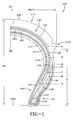
- Figure 1 is illustrative of a tire 100 having a tread region 112, two bead regions 114 (only one of which is shown) and two sidewalls 116 (only one of which is shown). Each sidewall extends between a respective one of the bead regions 114 and the tread region 112.
- the tread region 112 comprises a tread 120.
- the bead region 114 comprises a bead (or bead bundle) 122.
- a shoulder 118 of the tire is defined as the upper portion of sidewall 116 just below the lateral edge of the tread 120.
- a belt structure, or belt package 130 is disposed in the tread region 112, below the tread 120.
- a number of reinforcing plies 140 are disposed below the belt structure 130 and extend laterally beyond the lateral edges of the tread, radially in the sidewall to the bead(s) 122, wrap approximately 180 degrees around the beads, and extend radially back up into the sidewall 116.
- the portion(s) of the ply/plies 140 extending back up into the sidewall 116 is called the "turn-up".
- the tire carcass is defined as the tire structure apart from the belt structure 130, tread 120, and undertread (if any, not shown) over the ply/plies 140, but including the beads 122 and an inner liner (not shown) is disposed on the inner surface of the tire carcass.
- a crown of the tire 100 is defined as the tread 120, tread shoulders 118 and adjacent portions of the sidewalls 116.
- the tire 100 has a section height (SH) which is defined as the radial distance from the nominal rim diameter (NRD), or inner periphery of the tire 100 in the bead region 114, to the outer diameter of the tire (namely the tire tread 120) at its equatorial plane (EP).
- the tire 100 has a section width (SW) which is defined as the maximum linear distance parallel to the axis of the tire and between the exterior of its sidewalls 116 when and after the tire has been inflated at normal pressure for 24 hours, but unloaded, excluding elevations of the sidewalls due to labeling, decoration or protective bands.
- the tire has an aspect ratio (AR) which is defined as the ratio of the section height (SH) of the tire to its section width (SW).
- AR aspect ratio
- SH section height
- H height
- the belt package 130 comprises at least two belts - a first belt 132 and a second belt 134.
- the second belt 134 is disposed radially outward from the first belt 132.
- the belts 132, 134 both extend laterally across the tread region 112, and circumferentially around the tire, in a conventional manner.
- Each belt 132, 134 has lateral edges.
- the inner, or first belt 132 extends laterally across the tread region 112 and beyond the tread region 112 into the sidewall 116, its lateral edge being disposed at point which is a radial distance C from the NRD of the tire 100.
- the outer, or second belt 134 extends laterally approximately completely across the tread region 112, to approximately the shoulder 118 of the tire 100, its lateral edge being disposed at point which is a radial distance G from the NRD of the tire.
- the belts 132, 134 are preferably aramid belts, comprising reinforcing cords disposed at an angle in the range of between 0 and 45 degrees, preferably between 26-30 degrees, as measured with respect to the EP of the tire.
- the belts may also be formed of fiberglass with cords disposed at angles in the same range.
- the cords of one belt may be disposed at an angle which is different than, including opposite to those of the other belt.
- an important aspect of the invention is that at least one of the belts 132, 134 extends into the sidewall(s) of the tire.
- the inner/first belt 132 is shown extending into the sidewall 116 of the tire 100. It is within the scope of the invention that both belts 132, 134 can extend into the sidewalls 116 of the tire 100, to the same or different distances than one another. It is within the scope of the invention that a one of the belts extends into a one of the sidewalls of the tire, while the other of the belts extends into the other sidewall of the tire, which would result in an asymmetrical tire construction. There can, of course, be three or more belts, although only two are discussed with respect to the illustrated embodiment of the invention.
- the tire 100 has at least three reinforcing, or carcass plies - a first ply 142, a second ply 144, and a third ply 146.
- the labels “first”, “second” and “third” are indicative of the order in which the plies would typically be laid up, sequentially, upon a tire build drum).
- the second ply 144 is radially outward from the first ply 142.
- the third ply 146 is radially outward from the second ply 144.
- the plies 142, 144, 146 all extend from one bead 122, through the sidewall 116, across the tread region 112, through the other sidewall (not shown) to the other bead (not shown) of the tire, in a conventional manner.
- Each ply has two end portions, called “turn-ups", which are those portions of the ply which extend beyond the bead, back into the sidewall of the tire, in a conventional manner.
- the turn-up of the first ply 142 extends beyond the bead 122 into the sidewall 116, its end being disposed at point which is a radial distance F from the NRD of the tire.
- the turn-up of the second ply 144 extends beyond the bead 122 into the sidewall 116, its end being disposed at point which is a radial distance E from the NRD of the tire.
- the turn-up of the third ply 146 extends beyond the bead 122 into the sidewall 116, its end being disposed at point which is a radial distance B from the NRD of the tire 100.
- the plies 142, 144, 146 all have relatively "high" turn-up ends, which means that after wrapping (typically approximately 180 degrees) around the bead, the turn-up end portion of the ply extends substantially, such as at least H/3 (one-third (33%) of the height of the sidewall) into the sidewall 116 towards the tread region 112. As shown in Figure 1, the turn-ups extend progressively further into the sidewall of the tire, from the third ply 146 which is outermost with respect to the tire carcass (and closest to the bead 122) to the first ply 142 which is innermost with respect to the tire carcass (and furthest from the bead bundle). In “numerical" terms, F > E > B.
- the plies 142, 144, 146 are preferably rayon plies, comprising cords disposed at an angle in the range of between 15 and 40 degrees, preferably 26-30 degrees for bias ply constructions, or between 65 and 90 degrees, preferably 70-85 degrees for radial ply constructions as measured with respect to the EP of the tire.
- the plies may also be formed of nylon, with cords disposed at angles in the same range.
- the cords of one ply may be disposed at an angle which is different than, including opposite to those of the other plies.
- the bead 122 is preferably formed as heavy-duty, 5-strand bead construction. This is merely exemplary, and the number of wires is not critical.
- the bead is preferably stronger than that of a conventional motorcycle tire.
- the bundle width and diameter should be such that it provides a very tight fit in the bead seating region of the wheel. Pressure required to seat the beads may be higher than normal (e.g., >40 psi).
- the plies 142, 144, and 146 are arranged in a conventional manner in that they wrap around the bead, from inside the bead to outside the bead. It is within the scope of the invention that the plies could wrap from outside the bead to inside the bead, in which case the turn-ups would be on the inside, rather than on the outside of the respective ply.
- An apex 150 is disposed atop the bead 122.
- the apex 150 is formed of high-modulus elastomer and extends into the sidewall 116 towards the tread region 112.
- the apex is generally triangular in cross-section, and has a base 152 adjacent (proximal) the bead 122, and a tip 154 which is distal from the bead 122 at a point which is a radial distance D from the NRD of the tire.
- the apex 150 tapers in thickness from widest at its base 152, where its width is substantially equal to the cross-dimension of the bead 122, to narrowest at its tip, where its width is substantially zero.
- apex 150 is a standard hard structural apex. It serves the purpose of a lower sidewall EMT insert. Generally, apexes can also be used to modify the handling characteristics of a tire, e.g. to improve the steering response.
- the apex 150 is "tall" in that it extends quite far into the sidewall 116 towards the tread region 112, substantially, such as at least H/3 (one-third of the height of the sidewall) into the sidewall 116 towards the tread region 112.
- the turn-up of the ply 146 extends nearly to the tip 154 of the apex 150 (B ⁇ D)
- the turn-up of the ply 144 extends slightly beyond the tip 154 of the apex 150 (E > D)
- the turn-up of the ply 142 extends farther beyond the tip 154 of the apex 150 (F > E > D)
- a crown-reinforcing (C-R) insert 160 is disposed below the belt structure 130.
- the crown-reinforcing insert 160 is formed of elastomer and extends, preferably continuously, across the tread region 112, through the shoulder 118, into the sidewall 116 of the tire.
- the crown-reinforcing (C-R) insert 160 has a central portion 162 which is substantially at the EP of the tire 100, and lateral edges (tips) 164 (one shown) which is located in the sidewall 116 of the tire 100.
- the crown-reinforcing (C-R) insert 160 tapers in thickness from thickest in its central portion 162 to thinnest at its lateral edge (tip) 164.
- the lateral edge (tip) 164 of the crown-reinforcing insert 160 extends to a point which is a radial distance A from the NRD of the tire. From another perspective, it can be seen that the crown-reinforcing (C-R) insert 160 extends a percentage of the sidewall height (H), preferably at least 33% (one-third) of the sidewall height (H) in to the sidewall 116 of the tire 100.
- the crown-reinforcing (C-R) insert 160 is shown as being disposed between the ply 144 and the ply 146. In Figure 1, it is illustrated that the crown-reinforcing (C-R) insert 160 extends at least 50% of the sidewall height (H) in to the sidewall 116 of the tire 100.
- the crown-reinforcing (C-R) insert may also extend dis-continuously (with one or more gaps, or discontinuities) across the tread region 112, but some loss in runflat (e.g. 0 psi) handling would likely result from such interruptions in its structural integrity.
- the major purpose of the crown-reinforcing (C-R) insert is to stiffen the tread and upper sidewall region.
- motorcycle tires depend largely on their crown profile to provide lateral (or turning) forces. Without the crown-reinforcing (C-R) insert, the runflat handling of a motorcycle tire would be extremely sluggish.
- the thickness of the crown-reinforcing (C-R) insert may be thinner at the crown, to reduce heat build-up and allow speed rated tires.
- the crown-reinforcing (C-R) insert 160 extends quite far into the sidewall 116 towards the bead region 114, substantially, such as at least H/3 (one- third (33%) the height of the sidewall) into the sidewall 116 towards the bead region 114.
- the tip 154 of the apex 150 extends a point which is a radial distance D from the NRD of the tire
- the lateral edge 164 of the crown-reinforcing (C-R) insert 160 extends to a point which is a radial distance A from the NRD of the tire.
- the tip 164 of the crown-reinforcing (C-R) insert 160 is closer to the axis of the tire than the tip 154 of the apex 150 (A ⁇ D).
- Both the crown-reinforcing (C-R) insert 160 and apex 150 can be considered to have "end portions” or “tip portions”, which are those portions of the structure in the region of the lateral edge 164 or tip 154 of the respective crown-reinforcing (C-R) insert 160 or apex 150. Therefore, the tip portions of the crown-reinforcing (C-R) insert 160 and apex 150 "overlap" radially.
- the tip portion of the crown-reinforcing (C-R) insert 160 is axially inward of the tip portion of the apex 150, and the crown-reinforcing (C-R) insert 160 is completely separated (laterally spaced-apart) from the apex 150 by the ply 146.
- the insert 160 is also partially separated (laterally spaced-apart) from the apex by the belt 132. It is within the scope of the invention that the tip portion of the crown-reinforcing (C-R) insert 160 is axially outward of the tip portion of the apex 150.
- the crown-reinforcing (C-R) insert 160 is separated from the apex 150 by "something" - in this example, by the ply 146 - to avoid possible adhesion problems between the crown-reinforcing (C-R) insert 160 and the apex 150.
- the "something" separating the two components 150 and 160 could be a distinct separating element, such as a thermoplastic ribbon/layer). It is also within the scope of the invention that a single, dual-compounded element constituting both the crown-reinforcing (C-R) insert 160 and the apex 150 could be used.
- the crown-reinforcing (C-R) insert 160 is disposed between the ply 144 and the ply 146. It is however within the scope of the invention that the crown-reinforcing (C-R) insert 160 can be disposed interior to the ply 142, or between the plies 142 and 144, or between the ply 146 and the belt 132, or between any two adjacent layers of the sequence of reinforcing layers.
- the crown-reinforcing (C-R) insert 160 has a thickness T1 at its central portion 162, and tapers in thickness from a maximum thickness T2 at the shoulder portion 118 of the tire, to a thickness T3 at its lateral edge (tip) 164, where its thickness is substantially zero.
- T1 may be less than either of T2 or T3.
- T3 may be less than either of T2 or T3.
- T1-T3 are “approximate”, and are relative to either of the Section Height (SH) or Section Width (SW) being 150 mm.
- the term "approximate” means +/- 10% of the stated percentage.
- a key feature of the invention is the crown-reinforcing (C-R) insert 160 which extends from under the tread 120, substantially (at least one-third of the sidewall height) into the sidewall 116 of the tire 100, along with apexes 150 which extend substantially (at least one-third of the sidewall height) into the sidewall 116 of the tire, thereby effecting a substantial "overlap" between end portions of the crown-reinforcing (C-R) insert and the apexes.
- the overlap is the radial distance D (75%) minus the radial distance A (35%), or approximately one-third of the sidewall height (H).
- at least one belt 132 extends from under the tread substantially into the sidewall, and the turn-ups of the plies 140 extend quite high into the sidewall. This combination of features yields superior runflat performance.
- the invention is particularly useful for motorcycle tires, and for pneumatic tires having an aspect ratio (AR) which is at least 50%, preferably at least 75%, such as such as approximately 1 (100%).
- AR aspect ratio
Abstract
Description
- This invention relates to pneumatic tires and, more particularly, to runflat tires and, more particularly, to runflat motorcycle tires.
- Various methods have been devised for enabling the safe continued operation of un-pressurized or under pressurized vehicle tires with the intent of minimizing further damage to the uninflated tire and without compromising vehicle handling while driving to where the tire can be changed. Loss of tire pressure can result from a variety of causes, including puncture by a foreign object such as a nail. Pneumatic tires designed for sustained operation when "uninflated" ("flat") or under inflated are also called "runflat" tires, as they are capable of being driven in the "flat" condition. They are also called extended mobility technology tires, or "EMT" tires. A conventional pneumatic tire will collapse upon itself when it is uninflated and carrying the weight of a vehicle. The tire's sidewalls buckle outward in the circumferential portion of the tire where the tread contacts the ground, making the tire "flat."
- The term "runflat" is generally used to describe a tire that is designed such that the tire structure alone, and in particular the structure of the sidewalls, has sufficient strength and rigidity to support the vehicle load when the tire is operated without being inflated. The sidewalls and internal surfaces of such runflat tires or EMT tires do not collapse or buckle due to their rigidity, and the prevailing designs of such tires do not otherwise contain or use other supporting structures or devices to prevent the tire from collapsing. Examples of such other supporting structures are devices that might be contained within the tire and which experience no loading during normal inflated operation.
- In general, runflat tires or EMT tires incorporate sidewalls that are thicker and/or stiffer so that the tire's load can be carried by an uninflated tire with minimum adverse effects upon the tire itself and upon vehicle handling until such reasonable time as the tire can be repaired or replaced. The typical methods used in sidewall thickening and stiffening include the incorporation of circumferentially disposed wedge inserts in the inner peripheral surface of the sidewall portion of the carcass, which is the region in the tire usually having the lowest resistance to deformation under vertical loading. In such runflat tire designs, each sidewall is thickened in the region between the bead and the tread shoulder. The wedge inserts in each sidewall are generally crescent-shaped in cross-sectional view, in order to conform to the shape of the sidewalls. Such wedge reinforced sidewalls, when operated in the uninflated condition, experience a net compressive load in the region of the sidewall that is closest to the road-contacting portion of the tread. More specifically, the bending stresses on the sidewalls are such that the axially outwardmost portions of the reinforced sidewalls experience tensile stresses while the axially inward portions experience compressive stresses during runflat operation.
- A Goodyear patent, US-A- 5,368,082 ('082), by Oare et al, discloses a low aspect ratio runflat pneumatic radial ply tire which employs multiple wedge inserts in each sidewall to improve runflat stiffness. Approximately six additional pounds of weight per tire was required to support an 800 lb. load in this uninflated tire. This earlier invention, although superior to prior attempts at runflat tire design, still imposed a weight penalty which could, however, be partially offset by the elimination of a spare tire and the tire jack. However, this weight penalty becomes even more problematic in the design of tires having higher aspect ratios. The '082 patent teaches a sidewall construction for runflat tires in which the tire is constructed with two plies, an inner liner and two reinforcing wedge inserts in each sidewall. The two inserts in each sidewall are disposed such that one insert is located between the two plies while the other insert is located between the inner liner and the first or innermost ply.
- US-A- 5,427,166 and 5,511,599 of Walter L. Willard, Jr., show Michelin tires that incorporate an additional third ply and a third insert in the sidewall to further increase the runflat performance of the tire over that of the '082 patent. These Willard patents discuss some of the load relationships that occur in the uninflated condition of the tire and demonstrate that the concept taught in the '082 patent can be applied to additional numbers of plies as well as additional wedge inserts in each sidewall.
- However, such large amounts of rubber used to stiffen the sidewall members become factors in flexure heating that leads to tire failure during runflat operation. This is especially so when the tire is operated at high speeds during low or zero inflation. Therefore, one goal of runflat tire design is to minimize the number of wedge inserts used to stiffen each sidewall and the total amount of wedge insert material used in runflat tire.
- While the high resistance to compression and deflection of the inserts provides the necessary resistance to the collapse of the uninflated loaded tire, the use of multiple plies and more than one reinforcing wedge insert in each sidewall has drawbacks which include the above mentioned increase in tire weight and flexure-induced heat buildup. Such designs also increase the tire's complexity in ways that adversely affect manufacturing and quality control.
- Although many of the run-flat tire constructions set forth in the above-referenced patents have proven to be successful for certain applications, these constructions are usually found in low profile tires, that is, applications in which the tires have an aspect ratio of not more than 50%. These tires are of the type usually found on high performance vehicles. It is somewhat more difficult to implement run-flat tire constructions for higher profile tires, that is tires having an aspect ratio of greater than 50%, so that the tires have both sufficient uninflated durability and good subjective ride performance in the inflated condition.
- The following patents are also noted as being of interest.
- US-A- 3,911,987 (Takusagawa, et al.) discloses a pneumatic safety tire for motorcycles which includes a pair of elastic reinforcing layers disposed along the carcass plies of the tire and extending from proximal the tire beads to a tire inner surface under the tread rubber. The Shore A hardness of the reinforcing layer is 45 or more, so that the safety tire can run at a high speed even after puncture, while providing excellent handling characteristics under normal conditions.
- US-A- 4,203,481 (Ranik, Jr.) discloses a pneumatic tire, rim, and a combination thereof that yields improved stability characteristics when the tire is run flat. The tire has an asymmetric sidewall construction resulting from the inclusion of rubber inserts in its sidewalls of different bulk (thickness) than one another, and the rim has axially outward extending rim flange extensions which are angled in relation to the axis of rotation of the rim. The rubber inserts (13, 14) are located inwardly of the carcass reinforcing material or plies of the tire. The inserts are generally crescent-shaped, and are located at the midpoint of the sidewall; that is, the distance half way between the bead seat and the road engaging tread surface when the tire is mounted and inflated under normal conditions. The inserts are located inside the reinforcing body ply. The inserts in the vehicle side are 0.25 inches (0.63 cm) thick on one side of the tire and 0.20 inches (0.51 cm) thick on the other side of the tire. The modulus of the rubber compound utilized in the inserts is 1300 psi at 200% elongation.
- US-A- 4,265,288 (Kaneko, et al.) discloses a pneumatic safety tire having annular rubber reinforcements (sidewall inserts) having crescent sectional shape and applied to a tire carcass at tire sidewalls, the rubber of the reinforcements having a JIS hardness of not less than 70, a tensile stress (Mod25) after an aging test of not less than 10 kg/cm2, and a repulsive elasticity by Dunlop tripsometer of not less than 65%.
- US-A- 5,769,980 (Spragg, et al.) discloses a pneumatic passenger tire having an aspect ratio of greater than 50% and having crescent-shaped sidewall inserts.
- GB-A- 2,087,805 discloses a pneumatic safety tire having at least two carcass ply structures (38, 40), and disposed adjacent the radially inner surface of each ply structure (38,40) there is an annular elastomeric insert (42, 46). One insert (42) extends from the bead region radially outward, terminating beneath the tread reinforcing belt structure (36), preferably a distance from the tread edge a distance A of at least ten percent (10%) and not greater than forty percent (40%) of the tread width, such as approximately 25% of the tread width. The other insert (46) is disposed between reinforcing ply structures (38,40), and extends from the bead region radially outward, terminating beneath the tread reinforcing belt structure (36) in the same manner as the one insert (42). The elastomeric inserts (42) each have a thickness (B), a the maximum section diameter of the tire of at least one percent (1%), preferably at least 3% and not greater than 5% of the maximum section diameter of the tire. (The maximum section diameter of the tire is measured parallel to the rotational axis of the tire from the axially outer surfaces of the tire, exclusive of indicia, adornment and the like.) Each elastomeric insert (46) has a thickness C of at least one percent (1%), preferably in the range of 2-4%, and not greater than 5%, of the maximum section diameter of the tire.
- Clearly, the goal in runflat tire design is to provide a low-cost, light-weight tire that gives both good runflat vehicle handling as well as good service life during runflat operation, while providing excellent handling characteristics under normal operating conditions.
- According to the invention, a pneumatic tire comprising an elastomer crown-reinforcing insert disposed in a tread region of the tire and extending at least 33%, such as 50% of a sidewall height into sidewalls of the tire. Apexes extend from the beads of the tire at least one-third of the sidewall height, into the sidewalls of the tire, and there is preferably a radial overlap between end portions of the crown-reinforcing insert and the apexes. At least one belt extends from the tread region into the sidewalls, and turn-up portions of at least some of a plurality of plies extending at least one-third of the sidewall height, into the sidewall.
- According to an aspect of the invention, the tire has at least two belts, a first belt and a second belt, wherein the second belt is disposed radially outward from the first belt, and it is the first belt which extends beyond the tread region into the sidewall.
- According to an aspect of the invention, the tire has at least three reinforcing plies, a first ply, a second ply, and a third ply, wherein the second ply is radially outward from the first ply and the third ply is radially outward from the second ply, and each of the reinforcing plies has a turn-up which extends into the sidewall of the tire. In an embodiment of the invention, the crown-reinforcing insert is disposed between the second ply and the third ply. It is within the scope of the invention that, with very low profile tires, the number of plies may be reduced, in which case the crown-reinforcing insert would be place between the first and second plies.
- According to an aspect of the invention, the crown-reinforcing insert is formed of elastomer having a Shore A hardness of at least 60.
- Benefits and advantages of the invention will become apparent to those skilled in the art to which it pertains upon a reading and understanding of the following detailed specification.
- The structure, operation, and advantages of the invention will become further apparent upon consideration of the following description taken in conjunction with the accompanying drawings, wherein:
- Figure 1 is a meridional cross-sectional view of an embodiment of the tire of the present invention. It should be understood that only a relevant and illustrative portion of the tire is shown, another "half" of the tire being a mirror image of what is shown.
-
- "Apex" means an elastomeric filler located radially above the bead core and between the plies and the turn-up ends of the plies. The apex is sometimes referred to as a "bead filler".
- "Aspect Ratio" (AR) means the ratio of the section height (SH) of a tire to its section width (SW). This term is also used to refer to the cross-sectional profile of the tire. A low-profile tire, for example, has a low aspect ratio.
- "Axial" and "Axially" means the lines or directions that are parallel to the axis of rotation of the tire.
- "Bead" or "Bead Core" generally means that part of the tire comprising an annular tensile member of radially inner beads that are associated with holding the tire to the rim; the beads being wrapped by ply cords and shaped, with or without other reinforcement elements such as flippers, chippers, apexes or fillers, toe guards and chafers.
- "Belt Structure" or "Reinforcement Belts" or "Belt Package" means at least two annular layers or plies of parallel cords, woven or unwoven, underlying the tread, unanchored to the bead, and having both left and right cord angles in the range from 18° to 30° relative to the equatorial plane (EP) of the tire.
- "Bias ply tire" means a belted or circumferentially-restricted pneumatic tire in which at least one ply has cords which extend from bead to bead are laid at cord angles less than 65 degrees, typically 15-40 degrees, with respect to the equatorial plane (EP) of the tire (Compare "Radial ply tire").
- "Carcass" means the tire structure apart from the belt structure, tread, and undertread over the plies, but including the beads.
- "Circumferential" most often means circular lines or directions extending along the perimeter of the surface of the annular tread of the tire, perpendicular to the axial direction. It can also refer to the direction of the sets of adjacent circular curves whose radii define the axial curvature of the tread, as viewed in cross section.
- "Cord" means one of the reinforcement strands, including fibers, with which the plies and belts are reinforced.
"Crown" or "Tire crown" means the tread, tread shoulders and adjacent portions of the sidewalls. - "Equatorial Plane" (EP) means the plane perpendicular to the tire's axis of rotation and passing through the center of its tread, or the plane containing the circumferential centerline of the tread.
- "EMT tire" means "extended mobility technology tire," and can be used interchangeably with "runflat tire."
- "Inner liner" means the layer or layers of elastomer or other material that form the inside surface of a tubeless tire and that contain the inflating fluid (e.g., air) within the tire.
- "Lateral" means a direction parallel to the axial direction.
- "Meridional" refers to a direction parallel to the axial direction but, more specifically, to a laterally disposed curved line that lies in a plane that includes the axis of the tire.
- "NRD" means nominal rim diameter, which is substantially equal to the diameter of the tire at the inner surface of the bead region. It is the outside diameter of a rim upon which the tire is intended to be mounted.
- "Ply" means a cord-reinforced layer of rubber-coated radially deployed, parallel cords.
- "Radial" and "radially" mean directions radially toward or away from the axis of rotation of the tire.
- "Radial ply structure" means the one or more carcass plies or which at least one ply has reinforcing cords oriented at an angle of between 65 and 90 degrees with respect to the equatorial plane (EP) of the tire.
- "Radial ply tire" means a belted or circumferentially-restricted pneumatic tire in which at least one ply has cords which extend from bead to bead are laid at cord angles between 65 and 90 degrees with respect to the equatorial plane (EP) of the tire.
- "Runflat" or "runflat tire" is a pneumatic tire that is designed to provide limited service while uninflated or underinflated.
- "Section height" (SH) means the radial distance from the nominal rim diameter (NRD) to the outer diameter of the tire at its equatorial plane (EP).
- "Section width" (SW) means the maximum linear distance parallel to the axis of the tire and between the exterior of its sidewalls when and after the tire has been inflated at normal pressure for 24 hours, but unloaded, excluding elevations of the sidewalls due to labeling, decoration or protective bands.
- "Shoulder" means the upper portion of sidewall just below the lateral edge of the tread.
- "Tread" means the ground-contacting portion of the tire.
- "Turn-up" or "turn-up end" means the end portion of a carcass reinforcing ply that extends radially outward, beyond the bead core around which the ply is wrapped (typically 180 degrees).
- "Sidewall" means that portion of a tire between the tread region and the and the bead region.
- Figure 1 is illustrative of a
tire 100 having atread region 112, two bead regions 114 (only one of which is shown) and two sidewalls 116 (only one of which is shown). Each sidewall extends between a respective one of thebead regions 114 and thetread region 112. Thetread region 112 comprises atread 120. Thebead region 114 comprises a bead (or bead bundle) 122. Ashoulder 118 of the tire is defined as the upper portion ofsidewall 116 just below the lateral edge of thetread 120. A belt structure, orbelt package 130 is disposed in thetread region 112, below thetread 120. A number of reinforcingplies 140 are disposed below thebelt structure 130 and extend laterally beyond the lateral edges of the tread, radially in the sidewall to the bead(s) 122, wrap approximately 180 degrees around the beads, and extend radially back up into thesidewall 116. The portion(s) of the ply/plies 140 extending back up into thesidewall 116 is called the "turn-up". The tire carcass is defined as the tire structure apart from thebelt structure 130,tread 120, and undertread (if any, not shown) over the ply/plies 140, but including thebeads 122 and an inner liner (not shown) is disposed on the inner surface of the tire carcass. A crown of thetire 100 is defined as thetread 120, treadshoulders 118 and adjacent portions of thesidewalls 116. Thetire 100 has a section height (SH) which is defined as the radial distance from the nominal rim diameter (NRD), or inner periphery of thetire 100 in thebead region 114, to the outer diameter of the tire (namely the tire tread 120) at its equatorial plane (EP). Thetire 100 has a section width (SW) which is defined as the maximum linear distance parallel to the axis of the tire and between the exterior of itssidewalls 116 when and after the tire has been inflated at normal pressure for 24 hours, but unloaded, excluding elevations of the sidewalls due to labeling, decoration or protective bands. Since Figure 1 shows only half of the tire, the width as illustrated is half the section width (SW/2). The tire has an aspect ratio (AR) which is defined as the ratio of the section height (SH) of the tire to its section width (SW). Thesidewall 116 has a height (H), which is defined as the radial distance from the NRD to theshoulder 118 of thetire 100. This is conventional tire design and terminology. - The
belt package 130 comprises at least two belts - afirst belt 132 and asecond belt 134. Thesecond belt 134 is disposed radially outward from thefirst belt 132. Thebelts tread region 112, and circumferentially around the tire, in a conventional manner. Eachbelt - The inner, or
first belt 132 extends laterally across thetread region 112 and beyond thetread region 112 into thesidewall 116, its lateral edge being disposed at point which is a radial distance C from the NRD of thetire 100. The outer, orsecond belt 134 extends laterally approximately completely across thetread region 112, to approximately theshoulder 118 of thetire 100, its lateral edge being disposed at point which is a radial distance G from the NRD of the tire. - The
belts - An important aspect of the invention is that at least one of the
belts first belt 132 is shown extending into thesidewall 116 of thetire 100. It is within the scope of the invention that bothbelts sidewalls 116 of thetire 100, to the same or different distances than one another. It is within the scope of the invention that a one of the belts extends into a one of the sidewalls of the tire, while the other of the belts extends into the other sidewall of the tire, which would result in an asymmetrical tire construction. There can, of course, be three or more belts, although only two are discussed with respect to the illustrated embodiment of the invention. - The
tire 100 has at least three reinforcing, or carcass plies - afirst ply 142, asecond ply 144, and athird ply 146. (The labels "first", "second" and "third" are indicative of the order in which the plies would typically be laid up, sequentially, upon a tire build drum). Thesecond ply 144 is radially outward from thefirst ply 142. Thethird ply 146 is radially outward from thesecond ply 144. Theplies bead 122, through thesidewall 116, across thetread region 112, through the other sidewall (not shown) to the other bead (not shown) of the tire, in a conventional manner. Each ply has two end portions, called "turn-ups", which are those portions of the ply which extend beyond the bead, back into the sidewall of the tire, in a conventional manner. - The turn-up of the
first ply 142 extends beyond thebead 122 into thesidewall 116, its end being disposed at point which is a radial distance F from the NRD of the tire. The turn-up of thesecond ply 144 extends beyond thebead 122 into thesidewall 116, its end being disposed at point which is a radial distance E from the NRD of the tire. The turn-up of thethird ply 146 extends beyond thebead 122 into thesidewall 116, its end being disposed at point which is a radial distance B from the NRD of thetire 100. - An important aspect of the invention is that the
plies sidewall 116 towards thetread region 112. As shown in Figure 1, the turn-ups extend progressively further into the sidewall of the tire, from thethird ply 146 which is outermost with respect to the tire carcass (and closest to the bead 122) to thefirst ply 142 which is innermost with respect to the tire carcass (and furthest from the bead bundle). In "numerical" terms, F > E > B. It is within the scope of the invention that two or more of the plies extend the same distance into the sidewall (e.g., F = E, or E = B). It is within the scope of the invention that the progression of how far the turn-ups extend into the sidewalls is in the reverse order from what is shown (i.e., F < E < B). Other "combinations" are also possible (e.g., F > E and B > E, with F either equal to or not equal to B). - The
plies - The
bead 122 is preferably formed as heavy-duty, 5-strand bead construction. This is merely exemplary, and the number of wires is not critical. The bead is preferably stronger than that of a conventional motorcycle tire. The bundle width and diameter should be such that it provides a very tight fit in the bead seating region of the wheel. Pressure required to seat the beads may be higher than normal (e.g., >40 psi). - As shown in Figure 1, the
plies - An apex 150 is disposed atop the
bead 122. The apex 150 is formed of high-modulus elastomer and extends into thesidewall 116 towards thetread region 112. The apex is generally triangular in cross-section, and has a base 152 adjacent (proximal) thebead 122, and atip 154 which is distal from thebead 122 at a point which is a radial distance D from the NRD of the tire. The apex 150 tapers in thickness from widest at itsbase 152, where its width is substantially equal to the cross-dimension of thebead 122, to narrowest at its tip, where its width is substantially zero. - Apexes, per se, are common in tire construction, and they serve to separate the turn-ups from the plies themselves. The apex 150 is a standard hard structural apex. It serves the purpose of a lower sidewall EMT insert. Generally, apexes can also be used to modify the handling characteristics of a tire, e.g. to improve the steering response.
- An important aspect of the invention is that the apex 150 is "tall" in that it extends quite far into the
sidewall 116 towards thetread region 112, substantially, such as at least H/3 (one-third of the height of the sidewall) into thesidewall 116 towards thetread region 112. - As illustrated, the turn-up of the
ply 146 extends nearly to thetip 154 of the apex 150 (B < D), the turn-up of theply 144 extends slightly beyond thetip 154 of the apex 150 (E > D), and the turn-up of theply 142 extends farther beyond thetip 154 of the apex 150 (F > E > D) - A suitable material for the apex 150 is an elastomer, having the following material properties/characteristics:
- A crown-reinforcing (C-R) insert 160 is disposed below the
belt structure 130. The crown-reinforcinginsert 160 is formed of elastomer and extends, preferably continuously, across thetread region 112, through theshoulder 118, into thesidewall 116 of the tire. The crown-reinforcing (C-R) insert 160 has acentral portion 162 which is substantially at the EP of thetire 100, and lateral edges (tips) 164 (one shown) which is located in thesidewall 116 of thetire 100. The crown-reinforcing (C-R) insert 160 tapers in thickness from thickest in itscentral portion 162 to thinnest at its lateral edge (tip) 164. The lateral edge (tip) 164 of the crown-reinforcinginsert 160 extends to a point which is a radial distance A from the NRD of the tire. From another perspective, it can be seen that the crown-reinforcing (C-R) insert 160 extends a percentage of the sidewall height (H), preferably at least 33% (one-third) of the sidewall height (H) in to thesidewall 116 of thetire 100. - In Figure 1, the crown-reinforcing (C-R) insert 160 is shown as being disposed between the
ply 144 and theply 146. In Figure 1, it is illustrated that the crown-reinforcing (C-R) insert 160 extends at least 50% of the sidewall height (H) in to thesidewall 116 of thetire 100. - The crown-reinforcing (C-R) insert may also extend dis-continuously (with one or more gaps, or discontinuities) across the
tread region 112, but some loss in runflat (e.g. 0 psi) handling would likely result from such interruptions in its structural integrity. The major purpose of the crown-reinforcing (C-R) insert is to stiffen the tread and upper sidewall region. Motorcycle tires depend largely on their crown profile to provide lateral (or turning) forces. Without the crown-reinforcing (C-R) insert, the runflat handling of a motorcycle tire would be extremely sluggish. Preferably, the thickness of the crown-reinforcing (C-R) insert may be thinner at the crown, to reduce heat build-up and allow speed rated tires. - An important aspect of the invention is that the crown-reinforcing (C-R) insert 160 extends quite far into the
sidewall 116 towards thebead region 114, substantially, such as at least H/3 (one- third (33%) the height of the sidewall) into thesidewall 116 towards thebead region 114. As enumerated below, in a case that the radial distance A is 35% of the sidewall height (H), then the crown-reinforcing (C-R) insert 160 extends 65% (100% - 35%) into thesidewall 116 towards thebead region 114. - A suitable material for the crown-reinforcing
insert 160 is an elastomer, having the following material properties/characteristics after vulcanization: - As mentioned above, the
tip 154 of the apex 150 extends a point which is a radial distance D from the NRD of the tire, and thelateral edge 164 of the crown-reinforcing (C-R) insert 160 extends to a point which is a radial distance A from the NRD of the tire. As illustrated, thetip 164 of the crown-reinforcing (C-R) insert 160 is closer to the axis of the tire than thetip 154 of the apex 150 (A < D). Both the crown-reinforcing (C-R) insert 160 and apex 150 can be considered to have "end portions" or "tip portions", which are those portions of the structure in the region of thelateral edge 164 ortip 154 of the respective crown-reinforcing (C-R) insert 160 orapex 150. Therefore, the tip portions of the crown-reinforcing (C-R) insert 160 and apex 150 "overlap" radially. As illustrated, the tip portion of the crown-reinforcing (C-R) insert 160 is axially inward of the tip portion of the apex 150, and the crown-reinforcing (C-R) insert 160 is completely separated (laterally spaced-apart) from the apex 150 by theply 146. Theinsert 160 is also partially separated (laterally spaced-apart) from the apex by thebelt 132. It is within the scope of the invention that the tip portion of the crown-reinforcing (C-R) insert 160 is axially outward of the tip portion of the apex 150. - It is preferred that the crown-reinforcing (C-R) insert 160 is separated from the apex 150 by "something" - in this example, by the ply 146 - to avoid possible adhesion problems between the crown-reinforcing (C-R) insert 160 and the apex 150. (The "something" separating the two
components - In the illustrated embodiment of the invention, there are three plies and two belts (all of which are "reinforcing layers"), in the following order: ply 142, ply 144, ply 146,
belt 132,belt 134, as described hereinabove, and the crown-reinforcing (C-R) insert 160 is disposed between theply 144 and theply 146. It is however within the scope of the invention that the crown-reinforcing (C-R) insert 160 can be disposed interior to theply 142, or between theplies ply 146 and thebelt 132, or between any two adjacent layers of the sequence of reinforcing layers. - Suitable materials for the various tire components have been described hereinabove. A number of dimensions have been mentioned above. In an exemplary tire, the following dimensions are applicable, and are expressed in centimeters (cm):
- inner Diameter of the tire (=NRD), in the range of 35-55 cm, such as 45 cm;
- outer Diameter of the tire, in the range of 45-75 cm, such as 65 cm;
- section height (SH) in the range of 6-15 cm, such as 11 cm;
- section width (SW), in the range of 7-26 cm, such as 15 cm.;
- half section width (SW/2), in the range of 3.5-13 cm, such as 7.5 cm;
- sidewall height (H), in the range of 3.5- 10 cm, such as 9 cm.
-
- The following percentages for the parameters A-G are "approximate", and are relative to a sidewall height H = 9 cm. As used herein, the term "approximate" means +/- 10% of the stated percentage.
- Distance A, in the range of 3 - 5 cm, such as 4.0 cm, or 40% of H
- Distance B, in the range of 4 - 6 cm such as 4.5 cm, or 50% of H.
- Distance C, in the range of 4 - 7 cm such as 5.5 cm, or 60% of H.
- Distance D, in the range of 4 - 7 cm such as 6.0 cm, or 70% of H.
- Distance E, in the range of 5 - 7 cm such as 6.5 cm, or 72% of H.
- Distance F, in the range of 6 - 9 cm such as 7.0 cm, or 78% of H.
- Distance G, in the range of 9 - 9.5 cm such as 9.3 cm, or 103% of H (Note that the point at G is shown as not being within the sidewall).
-
- The crown-reinforcing (C-R) insert 160 has a thickness T1 at its
central portion 162, and tapers in thickness from a maximum thickness T2 at theshoulder portion 118 of the tire, to a thickness T3 at its lateral edge (tip) 164, where its thickness is substantially zero. (Note from the ranges set forth below that T1 may be less than either of T2 or T3). In an exemplary tire, the following dimensions are applicable, and are expressed in millimeters (mm). The following percentages for the parameters T1-T3 are "approximate", and are relative to either of the Section Height (SH) or Section Width (SW) being 150 mm. As used herein, the term "approximate" means +/- 10% of the stated percentage. - thickness T1, in the range of 1 - 5 mm, such as 3.0 mm, or 2.0 % of SW
- thickness T2, in the range of 1 - 5 mm, such as 3.0 mm, or 2.0 % of SW
- thickness T3, in the range of 1 - 2 mm, such as 1.0 mm, or 0.5 % of SW
-
- It can thus be seen that a key feature of the invention is the crown-reinforcing (C-R) insert 160 which extends from under the
tread 120, substantially (at least one-third of the sidewall height) into thesidewall 116 of thetire 100, along withapexes 150 which extend substantially (at least one-third of the sidewall height) into thesidewall 116 of the tire, thereby effecting a substantial "overlap" between end portions of the crown-reinforcing (C-R) insert and the apexes. In the example given above, the overlap is the radial distance D (75%) minus the radial distance A (35%), or approximately one-third of the sidewall height (H). Also, at least onebelt 132 extends from under the tread substantially into the sidewall, and the turn-ups of theplies 140 extend quite high into the sidewall. This combination of features yields superior runflat performance. - The invention is particularly useful for motorcycle tires, and for pneumatic tires having an aspect ratio (AR) which is at least 50%, preferably at least 75%, such as such as approximately 1 (100%).
Claims (10)
- A tire comprising a tread region (112), sidewalls (116) and beads (122), and further comprising a plurality reinforcing layers comprising at least one belt (130, 132, 134) in the tread region (112) and at least one ply (140, 142, 144, 146) extending from the tread region (112), through the sidewalls (116), around the beads (122), the (100) tire characterized by a crown-reinforcing insert (160) disposed in the tread region (112) between any two adjacent ones of the reinforcing layers.
- A tire, according to claim 1, further comprising apexes (150) extending from beads (122) of the tire (100) at least one-third of a sidewall height, into the sidewalls (116) of the tire (100), wherein there is a radial overlap between end portions of the crown-reinforcing (C-R) insert (160) and the apexes (150).
- A tire, according to claim 1 or 2, wherein the ends of turn-ups of the at least one ply (140, 142, 144) extend a distance of at least one third (H/3) the height (H) of the sidewall (116) into the sidewalls (116) towards the tread region (112).
- A tire, according to any of the preceding claims, wherein at least one belt (132) extending from the tread region (112) into the sidewalls (116).
- A pneumatic tire (100) comprising an elastomer crown-reinforcing (C-R) insert (160) disposed in a tread region (112) of the tire (100) and extending at least 33% of a sidewall height (H) into sidewalls (116) of the tire (100).
- A tire according to claim 5, further comprising apexes (150) extending from beads (122) of the tire (100) at least one-third of the sidewall height, into the sidewalls (116) of the tire (100), wherein there is a radial overlap between end portions of the crown-reinforcing (C-R) insert (160) and the apexes (150).
- A tire according to claim 6, wherein the apexes (150) are formed integrally with the crown-reinforcing (C-R) insert (160).
- A tire, according to claim 6, wherein the end portions of the crown-reinforcing (C-R) insert (160) are separated from the apexes (150) by a ply (140, 142, 144, 146) or a belt (130, 132, 134).
- A tire, according to claim 5, further comprising at least one belt (130, 132, 134) extending from the tread region (112) into the sidewalls (116), and turn-up portions of at least some of a plurality of plies (140, 142, 144, 146) extending at least one-third of the sidewall height, into the sidewall (116).
- A tire, according to claim 6, wherein the tire (100) is of radial ply or bias ply construction.
Applications Claiming Priority (2)
| Application Number | Priority Date | Filing Date | Title |
|---|---|---|---|
| US247646 | 1999-02-09 | ||
| US10/247,646 US6938659B2 (en) | 2002-09-19 | 2002-09-19 | Runflat tire having crown-reinforcing insert extending into the sidewalls |
Publications (3)
| Publication Number | Publication Date |
|---|---|
| EP1400374A2 true EP1400374A2 (en) | 2004-03-24 |
| EP1400374A3 EP1400374A3 (en) | 2004-08-04 |
| EP1400374B1 EP1400374B1 (en) | 2006-12-06 |
Family
ID=31946442
Family Applications (1)
| Application Number | Title | Priority Date | Filing Date |
|---|---|---|---|
| EP03103388A Expired - Fee Related EP1400374B1 (en) | 2002-09-19 | 2003-09-15 | Runflat tire having crown-reinforcing insert extending into the sidewalls |
Country Status (3)
| Country | Link |
|---|---|
| US (1) | US6938659B2 (en) |
| EP (1) | EP1400374B1 (en) |
| DE (1) | DE60310173T2 (en) |
Cited By (4)
| Publication number | Priority date | Publication date | Assignee | Title |
|---|---|---|---|---|
| EP1580038A1 (en) * | 2004-03-25 | 2005-09-28 | Sumitomo Rubber Industries Ltd. | Run-flat tire |
| EP1857300A1 (en) * | 2006-05-19 | 2007-11-21 | Marangoni Tyre S.p.A. | Vehicle run-flat tyre |
| US20150083296A1 (en) * | 2013-09-24 | 2015-03-26 | Bridgestone Americas Tire Operations, Llc | Tire with toroidal element |
| EP3129242A4 (en) * | 2014-04-07 | 2017-11-29 | Bridgestone Americas Tire Operations, LLC | Tire with pre-stressed toroidal element |
Families Citing this family (12)
| Publication number | Priority date | Publication date | Assignee | Title |
|---|---|---|---|---|
| US7624779B2 (en) * | 2005-09-01 | 2009-12-01 | Bridgestone Americas Tire Operations, Llc | Tire having a sidewall reinforcement |
| US20070044889A1 (en) * | 2005-09-01 | 2007-03-01 | Bridgestone Firestone North American Tire, Llc | Tire having a sidewall reinforcement |
| US7836929B2 (en) * | 2005-09-01 | 2010-11-23 | Bridgestone Americas Tire Operations, Llc | Tire having a sidewall reinforcement |
| US20100024960A1 (en) * | 2005-09-01 | 2010-02-04 | Bridgestone Americas Tire Operations, Llc | Body ply and insert assembly method |
| US20070137757A1 (en) * | 2005-12-15 | 2007-06-21 | Roman John P | Tire with improved high speed capability and a method of manufacturing |
| US20080142142A1 (en) * | 2006-12-15 | 2008-06-19 | Giorgio Agostini | Pneumatic run-flat tire |
| US9222622B2 (en) * | 2007-11-26 | 2015-12-29 | Air Products And Chemicals, Inc. | Vessels with personnel access provisions |
| CN104816594B (en) * | 2010-03-29 | 2017-06-30 | 株式会社普利司通 | Tire |
| JP6480699B2 (en) * | 2014-10-03 | 2019-03-13 | 株式会社ブリヂストン | Run flat tire |
| JP6412764B2 (en) * | 2014-10-03 | 2018-10-24 | 株式会社ブリヂストン | Run flat tire |
| JP6967949B2 (en) * | 2017-11-30 | 2021-11-17 | Toyo Tire株式会社 | Pneumatic tires |
| JP7287073B2 (en) * | 2019-04-04 | 2023-06-06 | 横浜ゴム株式会社 | motorcycle tire |
Citations (4)
| Publication number | Priority date | Publication date | Assignee | Title |
|---|---|---|---|---|
| EP0385192A1 (en) * | 1989-03-02 | 1990-09-05 | PIRELLI COORDINAMENTO PNEUMATICI Società per Azioni | High performance tire |
| EP0869015A1 (en) * | 1997-04-02 | 1998-10-07 | COMPAGNIE GENERALE DES ETABLISSEMENTS MICHELIN-MICHELIN & CIE | Tyre with simplified crown reinforcement |
| EP0928704A1 (en) * | 1997-12-29 | 1999-07-14 | PIRELLI PNEUMATICI S.p.A. | High transverse curvature tyre for two-wheeled vehicles |
| US6338374B1 (en) * | 1998-03-26 | 2002-01-15 | The Goodyear Tire & Rubber Company | Runflat tire with fabric underlay and tread insert |
Family Cites Families (22)
| Publication number | Priority date | Publication date | Assignee | Title |
|---|---|---|---|---|
| US2979100A (en) * | 1957-04-17 | 1961-04-11 | Firestone Tire & Rubber Co | Tire construction |
| JPS5249603B2 (en) | 1972-11-13 | 1977-12-19 | ||
| JPS5235161B2 (en) * | 1973-06-21 | 1977-09-07 | ||
| FR2238603B1 (en) * | 1973-07-27 | 1976-06-18 | Uniroyal | |
| JPS52149703A (en) * | 1976-06-09 | 1977-12-13 | Bridgestone Corp | Air contained tyre equipped with lug pattern |
| DE2836352A1 (en) * | 1978-08-19 | 1980-03-06 | Continental Gummi Werke Ag | VEHICLE TIRES |
| JPS5568406A (en) | 1978-11-20 | 1980-05-23 | Bridgestone Corp | Air-filled safety tire with effective puncture-proof drivability |
| US4203481A (en) | 1978-12-11 | 1980-05-20 | The Firestone Tire & Rubber Company | Pneumatic tire, rim and combination thereof |
| ZA817371B (en) | 1980-11-24 | 1982-10-27 | Goodyear Tire & Rubber | A pneumatic safety tire |
| JPS5820503A (en) * | 1981-07-29 | 1983-02-07 | Bridgestone Corp | Pneumatic radial tire for motorcycle |
| JPS6038212A (en) * | 1983-08-11 | 1985-02-27 | Sumitomo Rubber Ind Ltd | Tire for motorcycle |
| US4625288A (en) * | 1984-10-01 | 1986-11-25 | Tektronix, Inc. | Method and apparatus for creating a structured image data set based on acquired image data |
| DE3802503A1 (en) * | 1988-01-28 | 1989-08-10 | Continental Ag | VEHICLE TIRES |
| JP2895953B2 (en) * | 1990-11-13 | 1999-05-31 | 住友ゴム工業株式会社 | Pneumatic tire |
| US5368082A (en) | 1992-09-30 | 1994-11-29 | The Goodyear Tire & Rubber Company | Radial ply pneumatic tire |
| JPH06115309A (en) * | 1992-10-05 | 1994-04-26 | Sumitomo Rubber Ind Ltd | Pneumatic tire |
| US5427166A (en) | 1994-01-18 | 1995-06-27 | Michelin Recherche Et Technique S.A. | Run-flat tire with three carcass layers |
| US5526863A (en) * | 1994-04-18 | 1996-06-18 | Michelin Recherche Et Technique S.A. | Tire with reduced bead mass |
| US5769980A (en) * | 1996-11-13 | 1998-06-23 | Bridgestone/Firestone, Inc. | Pneumatic tire with sidewall inserts having specified extension underneath the belt package |
| JP3079049B2 (en) * | 1996-11-21 | 2000-08-21 | 住友ゴム工業株式会社 | Pneumatic tire |
| DE19845724A1 (en) * | 1998-10-05 | 2000-04-06 | Dunlop Gmbh | Pneumatic vehicle tires |
| JP4073606B2 (en) * | 2000-05-17 | 2008-04-09 | 住友ゴム工業株式会社 | Pneumatic tire |
-
2002
- 2002-09-19 US US10/247,646 patent/US6938659B2/en not_active Expired - Fee Related
-
2003
- 2003-09-15 DE DE60310173T patent/DE60310173T2/en not_active Expired - Lifetime
- 2003-09-15 EP EP03103388A patent/EP1400374B1/en not_active Expired - Fee Related
Patent Citations (4)
| Publication number | Priority date | Publication date | Assignee | Title |
|---|---|---|---|---|
| EP0385192A1 (en) * | 1989-03-02 | 1990-09-05 | PIRELLI COORDINAMENTO PNEUMATICI Società per Azioni | High performance tire |
| EP0869015A1 (en) * | 1997-04-02 | 1998-10-07 | COMPAGNIE GENERALE DES ETABLISSEMENTS MICHELIN-MICHELIN & CIE | Tyre with simplified crown reinforcement |
| EP0928704A1 (en) * | 1997-12-29 | 1999-07-14 | PIRELLI PNEUMATICI S.p.A. | High transverse curvature tyre for two-wheeled vehicles |
| US6338374B1 (en) * | 1998-03-26 | 2002-01-15 | The Goodyear Tire & Rubber Company | Runflat tire with fabric underlay and tread insert |
Cited By (8)
| Publication number | Priority date | Publication date | Assignee | Title |
|---|---|---|---|---|
| EP1580038A1 (en) * | 2004-03-25 | 2005-09-28 | Sumitomo Rubber Industries Ltd. | Run-flat tire |
| US7077182B2 (en) | 2004-03-25 | 2006-07-18 | Sumitomo Rubber Industries, Ltd. | Run-flat tire |
| EP1857300A1 (en) * | 2006-05-19 | 2007-11-21 | Marangoni Tyre S.p.A. | Vehicle run-flat tyre |
| US20150083296A1 (en) * | 2013-09-24 | 2015-03-26 | Bridgestone Americas Tire Operations, Llc | Tire with toroidal element |
| CN105579248A (en) * | 2013-09-24 | 2016-05-11 | 普利司通美国轮胎运营有限责任公司 | Cap ply reinforcement strip in pneumatic tire |
| US9919568B2 (en) * | 2013-09-24 | 2018-03-20 | Bridgestone Americas Tire Operations, Llc | Tire with toroidal element |
| EP3129242A4 (en) * | 2014-04-07 | 2017-11-29 | Bridgestone Americas Tire Operations, LLC | Tire with pre-stressed toroidal element |
| US10052919B2 (en) | 2014-04-07 | 2018-08-21 | Bridgestone Americas Tire Operations, Llc | Tire with pre-stressed toroidal element |
Also Published As
| Publication number | Publication date |
|---|---|
| EP1400374A3 (en) | 2004-08-04 |
| DE60310173D1 (en) | 2007-01-18 |
| DE60310173T2 (en) | 2007-10-11 |
| US20040055687A1 (en) | 2004-03-25 |
| EP1400374B1 (en) | 2006-12-06 |
| US6938659B2 (en) | 2005-09-06 |
Similar Documents
| Publication | Publication Date | Title |
|---|---|---|
| US6453961B1 (en) | Variable-stiffness wedge insert for runflat tire | |
| JP5284307B2 (en) | Underlay structure for crown reinforcement | |
| EP2130690B1 (en) | Tire with a sidewall rubber insert | |
| EP1400374B1 (en) | Runflat tire having crown-reinforcing insert extending into the sidewalls | |
| US6719029B2 (en) | Tire wall gauges to optimize runflat tire ride comfort | |
| US6923233B1 (en) | Runflat tire with sawtooth shaped insert | |
| EP1242256B1 (en) | Variable-stiffness wedge inserts for runflat tires | |
| US7281553B1 (en) | Tire with compression-bearing hoop structure | |
| EP1097048B1 (en) | Tread reinforcement means for extended mobility tire | |
| EP1181161B1 (en) | Reinforced wedge-insert construction for extended mobility tires | |
| US7104301B2 (en) | Discontinuous ply for runflat tire construction | |
| US6843293B1 (en) | Variable-stiffness wedge insert for runflat tires | |
| US6561245B1 (en) | Thread reinforcement means for extended mobility tire | |
| US6536495B1 (en) | Tread stiffening for two ply runflat tire | |
| US6763866B1 (en) | Reinforced wedge-insert construction for extended mobility tires | |
| US6695025B1 (en) | Runflat tire construction with ply cords having a variable modulus of elasticity | |
| EP1156937B1 (en) | Discontinuous ply for runflat tire construction | |
| WO2000020236A1 (en) | Improved construction for runflat tire | |
| EP1222079B1 (en) | Runflat tire with sawtooth shaped insert | |
| EP1126984B1 (en) | Tread stiffening for two-ply runflat tire |
Legal Events
| Date | Code | Title | Description |
|---|---|---|---|
| PUAI | Public reference made under article 153(3) epc to a published international application that has entered the european phase |
Free format text: ORIGINAL CODE: 0009012 |
|
| AK | Designated contracting states |
Kind code of ref document: A2 Designated state(s): AT BE BG CH CY CZ DE DK EE ES FI FR GB GR HU IE IT LI LU MC NL PT RO SE SI SK TR |
|
| AX | Request for extension of the european patent |
Extension state: AL LT LV MK |
|
| PUAL | Search report despatched |
Free format text: ORIGINAL CODE: 0009013 |
|
| AK | Designated contracting states |
Kind code of ref document: A3 Designated state(s): AT BE BG CH CY CZ DE DK EE ES FI FR GB GR HU IE IT LI LU MC NL PT RO SE SI SK TR |
|
| AX | Request for extension of the european patent |
Extension state: AL LT LV MK |
|
| 17P | Request for examination filed |
Effective date: 20050204 |
|
| AKX | Designation fees paid |
Designated state(s): DE FR GB |
|
| RBV | Designated contracting states (corrected) |
Designated state(s): DE FR GB |
|
| GRAP | Despatch of communication of intention to grant a patent |
Free format text: ORIGINAL CODE: EPIDOSNIGR1 |
|
| RTI1 | Title (correction) |
Free format text: RUNFLAT TIRE HAVING CROWN-REINFORCING INSERT EXTENDING INTO THE SIDEWALLS |
|
| GRAS | Grant fee paid |
Free format text: ORIGINAL CODE: EPIDOSNIGR3 |
|
| GRAA | (expected) grant |
Free format text: ORIGINAL CODE: 0009210 |
|
| AK | Designated contracting states |
Kind code of ref document: B1 Designated state(s): DE FR GB |
|
| REG | Reference to a national code |
Ref country code: GB Ref legal event code: FG4D |
|
| REF | Corresponds to: |
Ref document number: 60310173 Country of ref document: DE Date of ref document: 20070118 Kind code of ref document: P |
|
| ET | Fr: translation filed | ||
| PLBE | No opposition filed within time limit |
Free format text: ORIGINAL CODE: 0009261 |
|
| STAA | Information on the status of an ep patent application or granted ep patent |
Free format text: STATUS: NO OPPOSITION FILED WITHIN TIME LIMIT |
|
| 26N | No opposition filed |
Effective date: 20070907 |
|
| PGFP | Annual fee paid to national office [announced via postgrant information from national office to epo] |
Ref country code: GB Payment date: 20070809 Year of fee payment: 5 |
|
| GBPC | Gb: european patent ceased through non-payment of renewal fee |
Effective date: 20080915 |
|
| PG25 | Lapsed in a contracting state [announced via postgrant information from national office to epo] |
Ref country code: GB Free format text: LAPSE BECAUSE OF NON-PAYMENT OF DUE FEES Effective date: 20080915 |
|
| PGFP | Annual fee paid to national office [announced via postgrant information from national office to epo] |
Ref country code: DE Payment date: 20090930 Year of fee payment: 7 |
|
| REG | Reference to a national code |
Ref country code: FR Ref legal event code: ST Effective date: 20110531 |
|
| REG | Reference to a national code |
Ref country code: DE Ref legal event code: R119 Ref document number: 60310173 Country of ref document: DE Effective date: 20110401 |
|
| PG25 | Lapsed in a contracting state [announced via postgrant information from national office to epo] |
Ref country code: DE Free format text: LAPSE BECAUSE OF NON-PAYMENT OF DUE FEES Effective date: 20110401 Ref country code: FR Free format text: LAPSE BECAUSE OF NON-PAYMENT OF DUE FEES Effective date: 20100930 |
|
| PGFP | Annual fee paid to national office [announced via postgrant information from national office to epo] |
Ref country code: FR Payment date: 20090916 Year of fee payment: 7 |