EP1400289A1 - Rolling method, a roll mill and a screw-down structure - Google Patents
Rolling method, a roll mill and a screw-down structure Download PDFInfo
- Publication number
- EP1400289A1 EP1400289A1 EP01274032A EP01274032A EP1400289A1 EP 1400289 A1 EP1400289 A1 EP 1400289A1 EP 01274032 A EP01274032 A EP 01274032A EP 01274032 A EP01274032 A EP 01274032A EP 1400289 A1 EP1400289 A1 EP 1400289A1
- Authority
- EP
- European Patent Office
- Prior art keywords
- rolls
- rolling
- poles
- cores
- iii
- Prior art date
- Legal status (The legal status is an assumption and is not a legal conclusion. Google has not performed a legal analysis and makes no representation as to the accuracy of the status listed.)
- Granted
Links
Images

Classifications
-
- B—PERFORMING OPERATIONS; TRANSPORTING
- B21—MECHANICAL METAL-WORKING WITHOUT ESSENTIALLY REMOVING MATERIAL; PUNCHING METAL
- B21B—ROLLING OF METAL
- B21B31/00—Rolling stand structures; Mounting, adjusting, or interchanging rolls, roll mountings, or stand frames
- B21B31/16—Adjusting or positioning rolls
- B21B31/20—Adjusting or positioning rolls by moving rolls perpendicularly to roll axis
-
- B—PERFORMING OPERATIONS; TRANSPORTING
- B21—MECHANICAL METAL-WORKING WITHOUT ESSENTIALLY REMOVING MATERIAL; PUNCHING METAL
- B21B—ROLLING OF METAL
- B21B13/00—Metal-rolling stands, i.e. an assembly composed of a stand frame, rolls, and accessories
- B21B13/02—Metal-rolling stands, i.e. an assembly composed of a stand frame, rolls, and accessories with axes of rolls arranged horizontally
-
- B—PERFORMING OPERATIONS; TRANSPORTING
- B21—MECHANICAL METAL-WORKING WITHOUT ESSENTIALLY REMOVING MATERIAL; PUNCHING METAL
- B21B—ROLLING OF METAL
- B21B1/00—Metal-rolling methods or mills for making semi-finished products of solid or profiled cross-section; Sequence of operations in milling trains; Layout of rolling-mill plant, e.g. grouping of stands; Succession of passes or of sectional pass alternations
- B21B1/22—Metal-rolling methods or mills for making semi-finished products of solid or profiled cross-section; Sequence of operations in milling trains; Layout of rolling-mill plant, e.g. grouping of stands; Succession of passes or of sectional pass alternations for rolling plates, strips, bands or sheets of indefinite length
-
- B—PERFORMING OPERATIONS; TRANSPORTING
- B21—MECHANICAL METAL-WORKING WITHOUT ESSENTIALLY REMOVING MATERIAL; PUNCHING METAL
- B21B—ROLLING OF METAL
- B21B13/00—Metal-rolling stands, i.e. an assembly composed of a stand frame, rolls, and accessories
- B21B13/02—Metal-rolling stands, i.e. an assembly composed of a stand frame, rolls, and accessories with axes of rolls arranged horizontally
- B21B2013/028—Sixto, six-high stands
-
- B—PERFORMING OPERATIONS; TRANSPORTING
- B21—MECHANICAL METAL-WORKING WITHOUT ESSENTIALLY REMOVING MATERIAL; PUNCHING METAL
- B21B—ROLLING OF METAL
- B21B31/00—Rolling stand structures; Mounting, adjusting, or interchanging rolls, roll mountings, or stand frames
- B21B31/16—Adjusting or positioning rolls
- B21B31/20—Adjusting or positioning rolls by moving rolls perpendicularly to roll axis
- B21B31/32—Adjusting or positioning rolls by moving rolls perpendicularly to roll axis by liquid pressure, e.g. hydromechanical adjusting
-
- B—PERFORMING OPERATIONS; TRANSPORTING
- B21—MECHANICAL METAL-WORKING WITHOUT ESSENTIALLY REMOVING MATERIAL; PUNCHING METAL
- B21B—ROLLING OF METAL
- B21B37/00—Control devices or methods specially adapted for metal-rolling mills or the work produced thereby
- B21B37/58—Roll-force control; Roll-gap control
Definitions
- the present invention relates to rolling and can be used in mills for the hot/cold rolling of ferrous and non-ferrous metals and alloys and also for rolling nonmetal materials.
- a rolling process (Patent RU No 2139153, B21B 1/22, published 10.10.1999), according to which a rolling force distributed along roll barrels is produced with the aid of electromagnetic attractive or repulsive forces to be provided in an external electromagnetic field across a magnetic flux vector.
- the horizontal axes of the rolls are coincident with axes of symmetry of electromagnet poles, in which particular case the attractive forces of'the rolls toward the poles are substantially parallel to a rolling plane. For this very reason, the rolls are attracted to the opposite poles with no rolling force created.
- a greater part of magnetic field energy does not participate in producing the rolling force that is here produced only by forces of attraction of the rolls to one another when being magnetized. Said circumstance is a drawback of the known rolling process as not allowing one to use all of the magnetic flux to produce said rolling force as much as possible.
- rolls are disposed in an external electromagnetic or magnetic field such that a field vector is directed along a diametral plane of a roll being in parallel relation to the rolling plane.
- An electric current is passed through the rolls thereat.
- Pressure on the rolls is distributed by changing a magnetic flux density along the generating line of roll barrels.
- a rolling force is created on account of the attractive forces of rolls used and also of forces of repulsion thereof.
- the poles of electromagnet means or magnet means are located between the diametral plane of the roll and the rolling plane.
- the electromagnet means or magnet means are provided with the like poles thereof with respect to each other, with a faculty of rotation thereof in a horizontal plane.
- the stand of the invention is provided with at least a pair of press rolls. The latter are disposed with freedom to move in a vertical plane and situated between the poles of electromagnet means or magnet means.
- the magnet means are adapted to move in the horizontal plane.
- At least one pair of permanent magnets or electromagnets have a capability of movement in the horizontal and vertical planes, Magnetic circuits are made up of the permanent magnets and provided with control coils supplied with pulse currents of a different correction sense.
- a drawback of the screwdown mechanism of a known stand is the low speed and accuracy of adjusting a clearance between rolls.
- the travel speed of housing screws in the QUARTO stands of hot rolling finishing mill group 2000 is from 0.5 to 1 mm/s. (P.I. Poloukhin "Rolling", Moscow, METALLURGIYA Publishers, 1982, page 386).
- a low accuracy of rolling is also explained by an appreciable amount of springing of said stand screwdown mechanism elements.
- the travel speed of the rods of hydraulic screwdowns (HS), according to these information sources, is 2.5 mm/s.
- the accuracy of adjustment is limited by the springing of elements of a hydraulic screwdown and a degree of elastic deformation of oil accounting for about 0.5 to 1%.
- a disadvantage of the known screwdown mechanism is the impossibility to use it in updating the existing stands equipped with housing screws with an electromechanical drive means, and hydraulic screwdowns which directly affect the rolls via chucks.
- the task of the present invention is to simplify the design of a stand, increase the speed and accuracy of adjusting a clearance between rolls, and precisely regulating a force produced in rolling operations.
- the task set is accomplished owing to the fact that in a rolling process by which to create and regulate a rolling force through an electromagnetic system intended for cooperation with stand rolls, the rolling force is produced by electromagnets with III-like cores to be disposed symmetrically of a rolling plane such that the poles of said III-like cores embrace the rolls beneath their diametral planes parallel to the rolling plane, on the side of the latter, the internal poles embracing working rolls and the external poles - press rolls, the rolling force being regulated by changing a current intensity in the coils of said III-like cores.
- a rolling force can be increased by auxiliary press rolls by electromagnetic effects produced on said auxiliary press rolls.
- the delicate adjustment of a rolling force is carried out by changing current level and/or issuing current pulses into the electromagnetic systems of a screwdown mechanism which are provided for the movable and stationary units of the screwdown mechanism, say, hydraulic system units.
- the stand of the invention comprises a housing made of nonmagnetic material, working and press rolls, a roll drive means and an electromagnetic system, said rolls are adapted to move in a vertical plane, the electromagnetic system is configured as at least one pair of III-like cores with coils embracing the internal poles of said cores; between the poles of said III-like cores, provision is made of working and press rolls, said III-like cores are disposed symmetrically of a rolling plane, the poles of said III-like cores embrace the rolls beneath their diametral planes being parallel to the rolling plane, on the side of the rolling plane and, along with this, the internal poles encompass the working rolls and the external poles - the press rolls.
- the stand is preferably provided with the supports of an electromagnetic system, which in turn may be equipped with travel mechanisms such as hydraulic cylinders.
- a stand can be provided with a pair of auxiliary press rolls and auxiliary press roll electromagnetic systems for cooperation with the auxiliary press rolls.
- the electromagnetic systems of auxiliary press rolls of a stand are preferably installed with a faculty of vertical movements with respect to a housing.
- a stand For the delicate regulation of a rolling force, a stand is provided with a screwdown mechanism comprising a hydraulic screwdown having a movable and stationary unit, both accommodating electromagnetic systems intended for interaction thereof.
- the screwdown mechanism may be composed of an electromechanical and/or hydraulic screwdown means in combination with the electromagnetic one.
- the screwdown mechanism of a stand comprises a hydraulic screwdown being comprised of a movable and stationary unit provided with electromagnetic systems for interaction thereof.
- the electromagnetic systems of a stand screwdown mechanism comprise at least two coils each, of which one is intended for connection to a d.c. source and the other in the form of an inductor is designated for connection to a discharge device, say, a capacitor bank associated with a control system, and a stationary unit is intended for cooperation with a housing screw of an electromechanical screwdown mechanism or a stand housing, while a movable unit - for articulated cooperation with a chuck of a press roll.
- an alleged invention makes it possible to appreciably expand the technological possibilities of stands for rolling strips by way of eliminating concentrated loads on roll necks, broadening a range of rolled strips, diminishing rejection as to size and improving rolling precision owing to an increase in the speed of response of a screwdown mechanism.
- a greater part of rolling force is created by electromagnetic volumetric forces (80-90%), the remaining part (10-20%) - by combined screwdown mechanisms (screw-HS) + (electromagnet) or (HS+ electromagnet); possible is a variant (screw+ electromagnet) ( ⁇ 100-200 tc) and, therefore, loading on roll necks will be reduced considerably. This will make it possible to diminish the diameters of the necks of press and working rolls, extend the service life of the rolls and bearings and appreciably decrease the longitudinal and transversal variations in thickness of the strips.
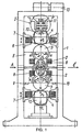
- FIG.I One of the embodiments of a rolling process is a stand schematically illustrated in Fig.I.
- the stand comprises a housing I made of nonmagnetic material, working rolls 2, press rolls 3, 4, III-like cores 5 with coils 6, solenoids 7, movable supports 8, supports 9 of hydraulic cylinders 10, housing screws II, chucks 12 of rolls the 4, and an electromechanical mechanism 13.
- the III-like electromagnet means are situated symmetrically of a vertical plane being perpendicular to a rolling plane 1 and being drawn through the centers of press and working rolls.
- the cores of said III-like electromagnet means are located between the diametral planes of the working and press rolls being in parallel relation to the rolling plane thereby to create the maximum forces of rolls attraction to the poles of the III-like electromagnet means. More, the relative position of the poles with respect to the vertical plane should correspond to the N-S-N or S-N-S diagram (cannot be otherwise).
- the distances "b" between the cores of the said III-like electromagnet means and rolls should be minimal, but not allowing their contact as the rolls wear out.
- the clearance "b" will gradually increase followed by the induction B and a rolling force diminishing little by little.
- the addition of currents to the coils of said III-like electromagnet means may be helpful in retaining the rolling force within specified limits on account of maintaining a certain magnetic flux density in the running clearance between the roll and the pole.
- the cores of said III-like electromagnet means being movable in vertical and horizontal planes, the size of an air gap can be adjusted mechanically, with its mean value maintained at constant level.
- the screwdown mechanism comprises a body 14 provided between a screw 11 and a chuck 12 of a roll 4 filled with oil 15, a hydraulic system 16.
- a movable unit 17 in the form of a piston
- a stationary unit 18 are arranged within the body 14, said units contain coils 19 provided , symmetrically of the body, connected to a d.c. source (not shown conventionally) and coils 20 in the form of inductors.
- the screwdown mechanism is connected with the screw II via a traverse 21 and with said chuck 12 body on the other side by means of traverses 22.
- the screwdown mechanism is capable of traveling together with the screw 11 and the chuck 12 in a vertical plane with the aid of a guide sleeve 23 secured on a housing I, of a commutation network 24.
- the stand is operated according to both QUARTO and SEXTO diagrams.
- the role of a screwdown mechanism is played by rolls 3, while rolls 4 perform the function of a mechanism of delicate adjustment of thickness of strip at the time of supplying currents of different signs into solenoids.
- the role of the screwdown mechanism is played by the rolls 3, 4 and a delicate adjustment of a strip section is carried out through current supply into coils 19 and electric impulses of different signs-into inductors 20.
- P 1 B 2 .S 1 . cos ⁇ ⁇ 0
- P 2 B 2 .S 2 . cos ⁇
- P 3 B 2 .S 3 2 ⁇ 0
- P h PD 2 p 4 .
- P h PD 2 p 4 .
- P el PD 2 p 4 .
- P mf PD 2 p 4 . P mf ;
- the stand is operated in the following manner.
- the automatic delicate adjustment of the thickness and section of a strip is carried out by issuing short electric impulses ⁇ ⁇ 10 -4 ⁇ 10 -6 C into coils 19 and inductors 20 being different as to intensity and sign.
- a cavity "A" of a body 14 is connected with a drain line and the currents are supplied into coils 19 from a d.c. source of a direction when the surfaces of movable and stationary units facing each other have a different polarity (N-S).
- a movable unit will be attracted to the stationary one, and a screwdown mechanism with a chuck 12 and a roll 4 will travel in the screw 11 movement direction (up and down).
- a strip thickness automatic regulation system delivers the pulses (discharges) of strong currents into inductors 20 of one or different directions (1 ⁇ 10 5 A, t ⁇ 10 -5 c), a factor that makes it possible to remove momentarily impermissible variations in thickness lengthwise of the strip.
Landscapes
- Engineering & Computer Science (AREA)
- Mechanical Engineering (AREA)
- Metal Rolling (AREA)
- Nitrogen And Oxygen Or Sulfur-Condensed Heterocyclic Ring Systems (AREA)
Abstract
Description
- Ph = 0 ÷ 250 kgf/cm2, (0 ÷ 250.105 Pa),
- Pel = 0-15 kg /cm2, (0-15 . 105 Pa),
- Pmf = 0-100 kgf/mm2, (109 Pa)
n - number of turns of an inductor, Jin current in the inductor,
a - current band width of an inductor.
Claims (9)
Said amendments have been made for the purpose of observing the requirement of unity of invention and having a better insight into a concept of invention and they do not depart from the scope of the specification thus far submitted and the claims.
Applications Claiming Priority (3)
| Application Number | Priority Date | Filing Date | Title |
|---|---|---|---|
| RU2001108349A RU2207925C2 (en) | 2001-03-28 | 2001-03-28 | Method of rolling, stand of rolls and hold-down device of stands of rolls |
| RU2001108349 | 2001-03-28 | ||
| PCT/RU2001/000481 WO2002076644A1 (en) | 2001-03-28 | 2001-11-14 | Rolling method, a roll mill and a screw-down structure |
Publications (3)
| Publication Number | Publication Date |
|---|---|
| EP1400289A1 true EP1400289A1 (en) | 2004-03-24 |
| EP1400289A4 EP1400289A4 (en) | 2007-07-18 |
| EP1400289B1 EP1400289B1 (en) | 2010-12-29 |
Family
ID=20247751
Family Applications (1)
| Application Number | Title | Priority Date | Filing Date |
|---|---|---|---|
| EP01274032A Expired - Lifetime EP1400289B1 (en) | 2001-03-28 | 2001-11-14 | Rolling method and a rolling mill |
Country Status (5)
| Country | Link |
|---|---|
| EP (1) | EP1400289B1 (en) |
| JP (1) | JP4263486B2 (en) |
| DE (1) | DE60143772D1 (en) |
| RU (1) | RU2207925C2 (en) |
| WO (1) | WO2002076644A1 (en) |
Cited By (1)
| Publication number | Priority date | Publication date | Assignee | Title |
|---|---|---|---|---|
| EP1398089A4 (en) * | 2001-04-23 | 2005-08-10 | Otkrytoe Aktsionernoe Obschest | Pressure device for rolling mill |
Families Citing this family (6)
| Publication number | Priority date | Publication date | Assignee | Title |
|---|---|---|---|---|
| RU2272685C1 (en) * | 2004-08-23 | 2006-03-27 | Открытое акционерное общество "Северсталь" (ОАО "Северсталь") | Strip lengthwise rolling method and aggregate for performing the same |
| RU2348474C1 (en) * | 2007-05-24 | 2009-03-10 | Лев Георгиевич Делюсто | Screwdown structure of rolling mill |
| RU179561U1 (en) * | 2017-06-01 | 2018-05-17 | Лев Георгиевич Делюсто | UNIVERSAL MAGNETIC CART FOR STRIP ROLLING |
| CN110328235A (en) * | 2019-07-15 | 2019-10-15 | 上海大学 | A method of the high silicon steel cold rolling under magnetic field |
| CN116921429B (en) * | 2023-09-13 | 2023-12-08 | 福建紫金英菲迅应用材料有限公司 | Silver-copper alloy manufacturing system and manufacturing method thereof |
| CN120055033B (en) * | 2025-04-28 | 2025-09-23 | 龙岩学院 | Nickel-based target hot rolling equipment with adjustable rolling force and production method |
Family Cites Families (11)
| Publication number | Priority date | Publication date | Assignee | Title |
|---|---|---|---|---|
| DE2324400C3 (en) * | 1972-05-17 | 1979-10-25 | Hitachi, Ltd., Tokio | Hydraulic adjustment device for roll stands |
| FI52394C (en) * | 1975-12-31 | 1977-08-10 | Valmet Oy | Bending compensated, end-loaded roller, in particular a press roll in a paper machine. |
| JPS57206506A (en) * | 1981-06-12 | 1982-12-17 | Toshiba Corp | Rolling mill |
| DE3529720A1 (en) * | 1985-08-20 | 1987-03-05 | Mannesmann Ag | ARRANGEMENT OF A HYDRAULIC CONTROL CYLINDER |
| IT1239661B (en) * | 1990-02-28 | 1993-11-11 | Danieli Off Mecc | HYDRAULIC PRESSURE DEVICE |
| RU2125917C1 (en) * | 1997-10-29 | 1999-02-10 | Открытое акционерное общество "Северсталь" | Hydromechanical screwdown apparatus |
| RU2141880C1 (en) * | 1998-04-03 | 1999-11-27 | Открытое акционерное общество "Северсталь" | Rolling stand |
| RU2138346C1 (en) * | 1998-04-03 | 1999-09-27 | Открытое акционерное общество "Северсталь" | Rolling stand |
| RU2146971C1 (en) * | 1998-05-13 | 2000-03-27 | Открытое акционерное общество "Северсталь" | Lengthwise rolling method and rolling stand for performing the same |
| RU2149718C1 (en) * | 1999-01-27 | 2000-05-27 | Открытое акционерное общество "Северсталь" | Rolling stand |
| FR2792229B1 (en) * | 1999-04-16 | 2001-07-13 | Kvaerner Metals Clecim | HYDRAULIC TIGHTENING ROLLER |
-
2001
- 2001-03-28 RU RU2001108349A patent/RU2207925C2/en active
- 2001-11-14 EP EP01274032A patent/EP1400289B1/en not_active Expired - Lifetime
- 2001-11-14 WO PCT/RU2001/000481 patent/WO2002076644A1/en not_active Ceased
- 2001-11-14 JP JP2002575148A patent/JP4263486B2/en not_active Expired - Fee Related
- 2001-11-14 DE DE60143772T patent/DE60143772D1/en not_active Expired - Lifetime
Cited By (1)
| Publication number | Priority date | Publication date | Assignee | Title |
|---|---|---|---|---|
| EP1398089A4 (en) * | 2001-04-23 | 2005-08-10 | Otkrytoe Aktsionernoe Obschest | Pressure device for rolling mill |
Also Published As
| Publication number | Publication date |
|---|---|
| RU2207925C2 (en) | 2003-07-10 |
| DE60143772D1 (en) | 2011-02-10 |
| JP4263486B2 (en) | 2009-05-13 |
| WO2002076644A1 (en) | 2002-10-03 |
| EP1400289A4 (en) | 2007-07-18 |
| JP2004527378A (en) | 2004-09-09 |
| EP1400289B1 (en) | 2010-12-29 |
Similar Documents
| Publication | Publication Date | Title |
|---|---|---|
| EP3422562B1 (en) | Method for operating a transport device in the form of a linear motor with guideway stator | |
| EP1400289B1 (en) | Rolling method and a rolling mill | |
| CN103492603A (en) | Electromagnetic device for stabilizing and reducing the deformation of a strip made of ferromagnetic material, and related process | |
| DE102015004582A1 (en) | Device for holding, positioning and moving an object | |
| RU2146971C1 (en) | Lengthwise rolling method and rolling stand for performing the same | |
| EP0788418B1 (en) | Stud welding device | |
| CN102245322A (en) | Method and device for processing slabs | |
| CA3062239A1 (en) | Transport device in the form of a long-stator linear motor | |
| US5140208A (en) | Self-adjusting magnetic guidance system for levitated vehicle guideway | |
| EP1398089B1 (en) | Pressure device for rolling mill | |
| RU2138346C1 (en) | Rolling stand | |
| US3710067A (en) | Method and apparatus for widening the field of application of electro-erosion machining amd improving the conditions arising in the work gap | |
| RU2149718C1 (en) | Rolling stand | |
| CN103406353B (en) | A kind of cold-strip steel stretching-bending straightener with roll shifting function | |
| RU2139153C1 (en) | Rolling method | |
| JPH0131963B2 (en) | ||
| RU2166390C2 (en) | Rolling stand | |
| Umehara et al. | In situ observation of the behavior of abrasives in magnetic fluid grinding | |
| RU2272685C1 (en) | Strip lengthwise rolling method and aggregate for performing the same | |
| RU2348473C2 (en) | Rolling mill | |
| RU2001108349A (en) | Method of rolling, rolling stand and rolling mill pressing device | |
| RU2310527C2 (en) | Strip lengthwise rolling method and apparatus for performing the same | |
| CN220635813U (en) | A support roller changing device | |
| JP2849528B2 (en) | Hot dip galvanizing equipment for steel strip | |
| US1440222A (en) | Electromagnetically-operated plate or bar handling skid for rolling mills |
Legal Events
| Date | Code | Title | Description |
|---|---|---|---|
| PUAI | Public reference made under article 153(3) epc to a published international application that has entered the european phase |
Free format text: ORIGINAL CODE: 0009012 |
|
| 17P | Request for examination filed |
Effective date: 20031018 |
|
| AK | Designated contracting states |
Kind code of ref document: A1 Designated state(s): AT BE CH CY DE DK ES FI FR GB GR IE IT LI LU MC NL PT SE TR |
|
| RIC1 | Information provided on ipc code assigned before grant |
Ipc: B21B 31/20 20060101ALI20070329BHEP Ipc: B21B 13/02 20060101AFI20070329BHEP |
|
| A4 | Supplementary search report drawn up and despatched |
Effective date: 20070620 |
|
| 17Q | First examination report despatched |
Effective date: 20080523 |
|
| RBV | Designated contracting states (corrected) |
Designated state(s): DE |
|
| GRAP | Despatch of communication of intention to grant a patent |
Free format text: ORIGINAL CODE: EPIDOSNIGR1 |
|
| RTI1 | Title (correction) |
Free format text: ROLLING METHOD AND A ROLLING MILL |
|
| GRAS | Grant fee paid |
Free format text: ORIGINAL CODE: EPIDOSNIGR3 |
|
| GRAA | (expected) grant |
Free format text: ORIGINAL CODE: 0009210 |
|
| AK | Designated contracting states |
Kind code of ref document: B1 Designated state(s): DE |
|
| REF | Corresponds to: |
Ref document number: 60143772 Country of ref document: DE Date of ref document: 20110210 Kind code of ref document: P |
|
| REG | Reference to a national code |
Ref country code: DE Ref legal event code: R096 Ref document number: 60143772 Country of ref document: DE Effective date: 20110210 |
|
| PLBE | No opposition filed within time limit |
Free format text: ORIGINAL CODE: 0009261 |
|
| STAA | Information on the status of an ep patent application or granted ep patent |
Free format text: STATUS: NO OPPOSITION FILED WITHIN TIME LIMIT |
|
| 26N | No opposition filed |
Effective date: 20110930 |
|
| REG | Reference to a national code |
Ref country code: DE Ref legal event code: R097 Ref document number: 60143772 Country of ref document: DE Effective date: 20110930 |
|
| PGFP | Annual fee paid to national office [announced via postgrant information from national office to epo] |
Ref country code: DE Payment date: 20141111 Year of fee payment: 14 |
|
| REG | Reference to a national code |
Ref country code: DE Ref legal event code: R119 Ref document number: 60143772 Country of ref document: DE |
|
| PG25 | Lapsed in a contracting state [announced via postgrant information from national office to epo] |
Ref country code: DE Free format text: LAPSE BECAUSE OF NON-PAYMENT OF DUE FEES Effective date: 20160601 |