EP1400151B1 - Appareil de cuisson - Google Patents
Appareil de cuisson Download PDFInfo
- Publication number
- EP1400151B1 EP1400151B1 EP02738393A EP02738393A EP1400151B1 EP 1400151 B1 EP1400151 B1 EP 1400151B1 EP 02738393 A EP02738393 A EP 02738393A EP 02738393 A EP02738393 A EP 02738393A EP 1400151 B1 EP1400151 B1 EP 1400151B1
- Authority
- EP
- European Patent Office
- Prior art keywords
- heater
- appliance
- temperature
- heating
- cooking plate
- Prior art date
- Legal status (The legal status is an assumption and is not a legal conclusion. Google has not performed a legal analysis and makes no representation as to the accuracy of the status listed.)
- Expired - Lifetime
Links
Images
Classifications
-
- H—ELECTRICITY
- H05—ELECTRIC TECHNIQUES NOT OTHERWISE PROVIDED FOR
- H05B—ELECTRIC HEATING; ELECTRIC LIGHT SOURCES NOT OTHERWISE PROVIDED FOR; CIRCUIT ARRANGEMENTS FOR ELECTRIC LIGHT SOURCES, IN GENERAL
- H05B3/00—Ohmic-resistance heating
- H05B3/68—Heating arrangements specially adapted for cooking plates or analogous hot-plates
- H05B3/74—Non-metallic plates, e.g. vitroceramic, ceramic or glassceramic hobs, also including power or control circuits
- H05B3/746—Protection, e.g. overheat cutoff, hot plate indicator
-
- H—ELECTRICITY
- H05—ELECTRIC TECHNIQUES NOT OTHERWISE PROVIDED FOR
- H05B—ELECTRIC HEATING; ELECTRIC LIGHT SOURCES NOT OTHERWISE PROVIDED FOR; CIRCUIT ARRANGEMENTS FOR ELECTRIC LIGHT SOURCES, IN GENERAL
- H05B3/00—Ohmic-resistance heating
- H05B3/68—Heating arrangements specially adapted for cooking plates or analogous hot-plates
- H05B3/74—Non-metallic plates, e.g. vitroceramic, ceramic or glassceramic hobs, also including power or control circuits
- H05B3/742—Plates having both lamps and resistive heating elements
-
- H—ELECTRICITY
- H05—ELECTRIC TECHNIQUES NOT OTHERWISE PROVIDED FOR
- H05B—ELECTRIC HEATING; ELECTRIC LIGHT SOURCES NOT OTHERWISE PROVIDED FOR; CIRCUIT ARRANGEMENTS FOR ELECTRIC LIGHT SOURCES, IN GENERAL
- H05B2213/00—Aspects relating both to resistive heating and to induction heating, covered by H05B3/00 and H05B6/00
- H05B2213/07—Heating plates with temperature control means
Definitions
- the present invention relates to a cooking appliance having a cooking plate, such as of glass-ceramic material, and incorporating a radiant electric heater having multiple heating zones. Such multiple heating zones are arranged substantially side-by side, such as in concentric relationship.
- heaters having two or three concentrically-arranged heating zones, each of which zones contains one or more electric heating elements. It is arranged for a central heating zone to be energised alone, or together with the concentrically-arranged outer heating zone or zones. Such an arrangement enables heated areas of different sizes to be provided, to accommodate cooking vessels of correspondingly different sizes on the cooking plate overlying the heater.
- a switch device incorporating a differentially-expanding rod and tube combination which is arranged to extend across the heating zones of the heater.
- Such switch device is arranged to respond primarily to the central heating zone. This is achieved by providing one or more temperature-compensating sections of the rod and tube combination where it passes across the one or two outer heating zones, or by screening the rod and tube combination with thermal insulating material where it crosses the one or two outer heating zones.
- Such arrangements effectively thermally desensitise the rod and tube combination where it passes across the one or two outer heating zones, so that calibration of the switch device can be set under conditions where only the central heating zone is energised, without early switching of the switch device being effected when the one or two outer heating zones are additionally energised.
- the heating zones are therefore undivided and, as a result, boiling performance of a liquid in a vessel located over the heater on the cooking plate is poor, except when all heating zones are energised.
- a cooking appliance comprising a cooking plate and at least one radiant electric heater located behind the cooking plate, the heater having multiple heating zones arranged substantially side-by-side and each provided with at least one electric heating element, a first heating zone being arranged to be energised alone and together with one or more further zones of the multiple heating zones, and a temperature sensing assembly for sensing a temperature of the cooking plate, wherein the temperature sensing assembly incorporates an electrical component located in a position confined within the first heating zone and having an electrical parameter which changes as a function of temperature; and wherein electronic control apparatus is provided for the at least one heater and is connected to the electrical component by means of electrical leads, the electronic control apparatus being adapted to detect the number of heating zones of the at least one heater that are energised and to control energisation of the heater in dependence upon the detected electrical parameter of the electrical component and upon predicted temperature of the cooking plate covering that area of the cooking plate occupied by the heater.
- the multiple heating zones of the at least one heater may be undivided from one another.
- the multiple heating zones of the at least one heater may be concentrically arranged and such that the first heating zone is a central heating zone which is energisable alone and together with one or more further zones arranged concentrically therewith.
- the at least one heater may be provided with first and second heating zones, or first, second and third heating zones.
- the at least one heater may be provided with a dish-like support comprising or incorporating a base of thermal and electrical insulation material, the heating elements of the heating zones being supported relative to the base.
- the at least one heater may be provided with a peripheral wall of thermal and electrical insulation material.
- the peripheral wall may be separate from or integral with the base.
- the electrical component may comprise a resistance temperature detector, such as a platinum resistance temperature detector, whose electrical resistance changes as a function of temperature.
- the temperature sensing assembly may comprise a probe which extends from a periphery of the at least one heater across a plurality of the multiple heating zones.
- the electrical component may be provided within a tube of the probe assembly.
- the tube of the probe assembly may comprise metal, ceramic or glass-ceramic.
- the cooking plate may be of glass-ceramic material.
- the electronic control apparatus may be adapted to provide an initial temperature boost setting and/or rate of increase of temperature, in respect of the cooking plate, having regard to a selected energised heating zone or combination of energised heating zones.
- the electronic control apparatus may comprise a microprocessor-based controller.
- the arrangement of the temperature sensing assembly in the heater with the temperature-responsive electrical component located within the confines of the first heating zone, which is always energised, is advantageous in that the temperature-responsive electrical component responds primarily to the temperature in the first heating zone, although is thermally influenced to a small extent by the additional operation of the one or more Other heating zones. It follows that it is unnecessary to provide mechanical temperature compensation or physical screening where the temperature sensing assembly extends across the outer heating zone or zones. Furthermore, the cooperation between the electronic control apparatus and the temperature-responsive electrical component enables optimised heating rates and maximum safe temperatures of the cooking plate to be obtained regardless of the selected combination of the heating zones, and provides excellent boiling performance on the cooking plate in all heating zone combinations.
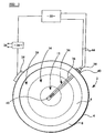
- a radiant electric heater 2 comprises a metal dish-like support 4 having therein a base 6 of thermal and electrical insulation material, such as microporous thermal and electrical insulation material, and a peripheral wall 8 of thermal and electrical insulation material.
- the peripheral wall 8 can be integral with, or separate from, the base 6 and is arranged to contact the underside of a cooking plate 10, such as of glass-ceramic material, when the heater 2 is installed for operation in a cooking appliance.
- An inner, or central, heating zone 12 is formed at the centre of the heater, an intermediate heating zone 14 is formed concentrically around the inner heating zone 12 and an outer heating zone 16 is formed concentrically around the intermediate heating zone 14.
- the central heating zone 12 is defined by at least one heating element 18, the intermediate heating zone 14 is defined by at least one heating element 20, and the outer heating zone 16 is defined by at least one heating element 22.
- the heating elements 18, 20, 22 are supported relative to the base 6 and comprise any of the well-known forms of element, such as wire, ribbon, foil or lamp forms of element, or combinations thereof.
- the heating elements 18, 20, 22 comprise corrugated ribbon heating elements supported edgewise on the base 6.
- the heating elements 18, 20, 22 are electrically connected to a terminal block 24 and arranged for energising from a power supply 26, through a relay 28 which is controlled by microprocessor-based electronic control apparatus 30.
- the heater 2 is arranged such that, when operated, the heating element or elements 18 in the central heating zone 12 is or are always energised, but can be energised additionally with the heating element or elements 20 in the intermediate heating zone 14 and further additionally with the heating element or elements 22 in the outer heating zone 16. This means that if it is required to heat a small cooking vessel 32A, located on the cooking plate 10 over substantially the central heating zone 12, only the central heating zone 12 will be arranged to be energised.
- the intermediate heating zone 14 will be arranged to be energised in addition to the central heating zone 12.
- both the intermediate heating zone 14 and the outer heating zone 16 will be arranged to be energised in addition to the central heating zone 12.
- a temperature sensing probe assembly 34 is arranged to extend from a periphery of the heater 2 across the three heating zones 12, 14, 16, in the space between the heating elements 18, 20, 22 and the cooking plate 10.
- the probe assembly 34 comprises a tube 36, such as of metal, ceramic or glass-ceramic, secured at an end 38 thereof to the metal dish-like support 4 of the heater 2 by means of a bracket 40.
- a resistance temperature detector (RTD) 42 particularly a platinum resistance temperature detector (PRTD), whose electrical resistance changes as a function of temperature, is located inside the tube 36 in a position such that it is confined within the central heating zone 12.
- the resistance temperature detector 42 has electrical leads 44 connected thereto which pass along the tube 36 and are arranged for connection to the electronic control apparatus 30.
- the construction of the temperature sensing probe assembly 34 may be as described in GB 0107042.4.
- resistance temperature detector 42 instead of the resistance temperature detector 42, another form of electrical component having an electrical parameter which changes as a function of temperature could be considered.
- the resistance temperature detector 42 Since the resistance temperature detector 42 is a relatively small discrete component located within the central heating zone 12, it responds primarily to the temperature in the central heating zone 12 and is thermally influenced to a minimal extent by the additional energising of the intermediate and outer heating zones 14 and 16. Calibration of the resistance temperature detector 42 is therefore affected only to a small extent whether or not the intermediate heating zone 14 is additionally energised, or both the intermediate heating zone 14 and the outer heating zone 16 are additionally energised, so that early switching off of the heating elements in response to the temperature sensing probe assembly 34 is unlikely to occur when one or both of the intermediate and outer heating zones 14, 16 is or are additionally energised.
- the resistance temperature detector 42 is calibrated in cooperation with the electronic control apparatus 30 such that, when a predetermined temperature is reached in the central heating zone 12, the one or more heating elements 18 is or are arranged to be de-energised and also the heating elements 20 and 22, if these were energised. Overheating of the cooking plate 10 and thermal damage thereto is thus avoided. This is particularly important when the cooking plate 10 is of glass-ceramic material.
- the electronic control apparatus 30 is adapted to detect the number of heating zones that are energised, namely whether the central heating zone 12 is energised alone, or with the intermediate heating zone 14, or with both the intermediate and outer heating zones 14 and 16. Such detection can be effected, for example, by determining whether or not a control knob is in a position to energise the respective heating zone.
- Energisation of the heater can be controlled as a result of such detection. For example, adjustment of energisation can be effected on the basis of a desired relationship between the electrical resistance of the resistance temperature detector 42 in the probe assembly 34, and predicted temperature of the cooking plate 10 over the entire heated area of the cooking plate 10.
- the glass temperature sensed by the detector 42 varies in dependence on which of the heating zones is or are energised, due to a heating effect on the tube 36.
- the control apparatus 30 can compensate for such variations electronically rather than by providing additional mechanical temperature compensation or thermal screening.
- the electronic control apparatus 30 may cooperate with the resistance temperature detector 42 and the electric heating elements 18, 20, 22, to provide an initial temperature boost setting and/or rate of increase of temperature, in respect of the cooking plate 10, having regard to whether the central heating zone 12 is energised alone, or with the addition of the intermediate heating zone 14, or with the further addition of the outer heating zone 16.
- the electronic control apparatus 30 may generate a temperature boost at the start of a cooking cycle by temporarily setting the maximum glass temperature to a higher value.
- the temporary maximum glass temperature can be adjusted in dependence upon which of the heating zones is or are energised.
- the cooperation between the electronic control apparatus 30 and the resistance temperature detector 42 enables optimised heating rates and maximum safe temperatures of the cooking plate 10 to be obtained, regardless of the selected combination of the energised heating zones 12, 14, 16, and provides excellent boiling performance in respect of a liquid in the cooking vessel 32A, 32B, 32C, in all heating zone combinations.
- a known form of cooking vessel detection arrangement (not shown) can be incorporated in the heater 2 and operating in association with the electronic control apparatus 30, to detect placement and removal of the cooking vessel 32A, 32B, 32C on and from the cooking plate 10 and effecting energising and de-energising of appropriate combinations of the heating elements 18, 20, 22.
- the heating zones 12, 14, 16 could be divided by walls of thermal insulation material 46 of well-known form, located therebetween and extending between the base 6 and the cooking plate 10.
- the heater 2 could be provided with a central heating zone and only one outer heating zone concentric therewith.
- the heater could have a central heating zone and more than two outer heating zones concentric therewith.
Claims (16)
- Appareil à cuisiner qui se compose d'une plaque de cuisson (10) et d'au moins un dispositif de chauffage électrique radiant (2) placé derrière la plaque de cuisson, le dispositif de chauffage ayant plusieurs zones chauffantes (12, 14, 16) agencées sensiblement côte à côte et chacune pourvue d'au moins un élément chauffant électrique (18, 20, 22), une première zone chauffante (12) étant agencée de sorte à être mise sous tension seule et conjointement avec une ou plusieurs autres zones (14, 16) parmi la pluralité de zones chauffantes et un ensemble capteur de température (34) pour capter une température de la plaque de cuisson, caractérisé en ce que l'ensemble capteur de température incorpore un composant électrique (42) placé en une position confinée à l'intérieur de la première zone chauffante (12) et ayant un paramètre électrique qui change en fonction de la température ; et en ce que l'appareil de commande électronique (30) est prévu pour au moins un dispositif de chauffage (2) et est connecté au composant électrique (42) au moyen de fils électriques (44), l'appareil de commande électronique étant adapté pour détecter le nombre de zones chauffantes du dispositif de chauffage (un au moins) qui sont sous tension et pour commander la mise sous tension du dispositif de chauffage en fonction du paramètre électrique détecté du composant électrique (42) et de la température prédite de la plaque de cuisson (10) qui recouvre la zone de la plaque de cuisson occupée par le dispositif de chauffage (2).
- Appareil selon la revendication 1, caractérisé en ce que la pluralité de zones chauffantes (12, 14, 16) du dispositif de chauffage (2) (un au moins) ne sont pas divisées l'une de l'autre.
- Appareil selon la revendication 1 ou 2, caractérisé en ce que la pluralité de zones chauffantes (12, 14, 16) du dispositif de chauffage (2) (un au moins) sont agencées concentriquement et de sorte que la première zone chauffante (12) est une zone chauffante centrale qui peut être mise sous tension seule ainsi qu'avec une ou plusieurs autres zones (14, 16) agencées concentriquement avec celle-ci.
- Appareil selon la revendication 1, 2 ou 3, caractérisé en ce que le dispositif de chauffage (2) (un au moins) est pourvu d'une première et d'une deuxième zones chauffantes.
- Appareil selon la revendication 1, 2 ou 3, caractérisé en ce que le dispositif de chauffage (2) (un au moins) est pourvu d'une première, d'une seconde et d'une troisième zones chauffantes.
- Appareil selon l'une quelconque des revendications précédentes, caractérisé en ce que le dispositif de chauffage (2) (un au moins) est pourvu d'un support (4) en forme de cuvette qui comprend ou incorpore une base (6) en matériau calorifuge et électriquement isolant, les éléments chauffants des zones chauffantes étant supportés relativement à la base.
- Appareil selon la revendication 6, caractérisé en ce que le dispositif de chauffage (2) (un au moins) est pourvu d'une paroi périphérique (8) en matériau calorifuge et électriquement isolant.
- Appareil selon l'une quelconque des revendications précédentes, caractérisé en ce que le composant électrique (42) comprend un détecteur de température à résistance dont la résistance électrique change en fonction de la température.
- Appareil selon la revendication 8, caractérisé en ce que le détecteur de température à résistance consiste en un détecteur de température à résistance en platine.
- Appareil selon l'une quelconque des revendications précédente, caractérisé en ce que l'ensemble de capteur de température (34) comprend une sonde qui s'étend depuis une périphérie du dispositif de chauffage (2) (un au moins) en travers de la pluralité de zones chauffantes (12, 14, 16).
- Appareil selon la revendication 10, caractérisé en ce que le composant électrique (42) ayant un paramètre électrique qui change en fonction de la température est prévu à l'intérieur d'un tube (36) de l'ensemble formant sonde.
- Appareil selon la revendication 11, caractérisé en ce que le matériau du tube (36) de l'ensemble formant sonde est sélectionné parmi métaux, céramiques et vitrocéramiques.
- Appareil selon l'une quelconque des revendications précédentes, caractérisé en ce que la plaque de cuisson (10) comprend un matériau en vitrocéramique.
- Appareil selon l'une quelconque des revendications précédentes, caractérisé en ce que l'appareil de commande électronique (30) est adapté pour produire un réglage d'augmentation initiale de la température relativement à la plaque de cuisson (10), compte tenu d'une zone chauffante sous tension sélectionnée ou à une combinaison de zones chauffantes sous tension.
- Appareil selon l'une quelconque des revendications précédentes, caractérisé en ce que l'appareil de commande électronique (30) est adapté pour produire une allure initiale d'augmentation de température relativement à la plaque de cuisson (10), compte tenu d'une zone chauffante sous tension sélectionnée ou à une combinaison de zones chauffantes sous tension.
- Appareil selon l'une quelconque des revendications précédentes, caractérisé en ce que l'appareil de commande électronique (30) comprend un contrôleur articulé sur microprocesseur.
Applications Claiming Priority (3)
| Application Number | Priority Date | Filing Date | Title |
|---|---|---|---|
| GBGB0115831.0A GB0115831D0 (en) | 2001-06-28 | 2001-06-28 | Radiant electric heater |
| GB0115831 | 2001-06-28 | ||
| PCT/GB2002/002936 WO2003003793A1 (fr) | 2001-06-28 | 2002-06-26 | Appareil de cuisson |
Publications (2)
| Publication Number | Publication Date |
|---|---|
| EP1400151A1 EP1400151A1 (fr) | 2004-03-24 |
| EP1400151B1 true EP1400151B1 (fr) | 2004-10-20 |
Family
ID=9917543
Family Applications (1)
| Application Number | Title | Priority Date | Filing Date |
|---|---|---|---|
| EP02738393A Expired - Lifetime EP1400151B1 (fr) | 2001-06-28 | 2002-06-26 | Appareil de cuisson |
Country Status (7)
| Country | Link |
|---|---|
| US (1) | US6995344B2 (fr) |
| EP (1) | EP1400151B1 (fr) |
| AT (1) | ATE280485T1 (fr) |
| DE (1) | DE60201683T2 (fr) |
| ES (1) | ES2231707T3 (fr) |
| GB (1) | GB0115831D0 (fr) |
| WO (1) | WO2003003793A1 (fr) |
Cited By (2)
| Publication number | Priority date | Publication date | Assignee | Title |
|---|---|---|---|---|
| WO2007044646A3 (fr) * | 2005-10-05 | 2007-07-12 | Evo Inc | Appareil de cuisson electrique |
| US8530795B2 (en) | 2009-06-26 | 2013-09-10 | Evo, Inc. | Electric cooking apparatus |
Families Citing this family (13)
| Publication number | Priority date | Publication date | Assignee | Title |
|---|---|---|---|---|
| EP1303169A1 (fr) * | 2001-10-15 | 2003-04-16 | Heraeus Sensor-Nite GmbH | Capteur de température utilisant un élément sensible ainsi que son utilisation |
| GB0301164D0 (en) | 2003-01-18 | 2003-02-19 | Ceramaspeed Ltd | Temperature-responsive device |
| DE10356432A1 (de) * | 2003-11-28 | 2005-06-23 | E.G.O. Elektro-Gerätebau GmbH | Temperatursensor auf Basis von Widerstandsmessung und Strahlungsheizkörper mit einem solchen Temperatursensor |
| GB0402412D0 (en) * | 2004-02-04 | 2004-03-10 | Ceramaspeed Ltd | Temperature sensor assembly |
| DE102005005520A1 (de) | 2005-02-01 | 2006-08-10 | E.G.O. Elektro-Gerätebau GmbH | Heizeinrichtung mit Temperatursensor und Kochfeld mit Heizeinrichtungen |
| US8353131B2 (en) * | 2006-01-12 | 2013-01-15 | Freet Patrick A | Loq-kit building component system |
| US20090194024A1 (en) * | 2008-01-31 | 2009-08-06 | Applied Materials, Inc. | Cvd apparatus |
| US9320293B2 (en) * | 2008-06-06 | 2016-04-26 | Gold Medal Products Company | Popcorn kettle |
| US8258437B2 (en) * | 2009-08-27 | 2012-09-04 | Whirlpool Corporation | Non-concentric surface heating element switch |
| US8274020B2 (en) * | 2010-05-04 | 2012-09-25 | Whirlpool Corporation | Apparatus and method of controlling a triple heating element of a cooking appliance |
| US10136664B2 (en) | 2016-07-11 | 2018-11-27 | Gold Medal Products Company | Popcorn popping machines and methods for different types of popcorn kernels and different popped popcorn types |
| US10757762B2 (en) * | 2017-12-01 | 2020-08-25 | Haier Us Appliance Solutions, Inc. | Electric cooktop appliance |
| US11570853B2 (en) * | 2021-02-01 | 2023-01-31 | E.G.O. Elektro-Geraetebau Gmbh | Method for actuating a heating device of a hob, and hob |
Family Cites Families (11)
| Publication number | Priority date | Publication date | Assignee | Title |
|---|---|---|---|---|
| GB2138659B (en) | 1980-01-14 | 1985-05-15 | Johnson Matthey Plc | Glass ceramic hob including temperature sensor |
| GB2103910B (en) | 1981-08-08 | 1985-08-21 | Micropore International Ltd | Improvements in electric cookers incorporating radiant heaters |
| DE3234349A1 (de) | 1982-09-16 | 1984-03-22 | Ego Elektro Blanc & Fischer | Heizkoerper fuer glaskeramikkochflaechen |
| EP0103741B1 (fr) * | 1982-09-16 | 1988-11-17 | E.G.O. Elektro-Geräte Blanc u. Fischer | Elément chauffant, en particulier élément chauffant radiant pour le chauffage de plaques en céramique |
| AT376540B (de) | 1983-01-05 | 1984-11-26 | Electrovac | Vorrichtung zur regelung bzw. begrenzung wenigstens eines temperaturwertes bzw. eines temperaturbereiches von strahlungs- bzw. kontaktheizkoerpern von elektrischen kochgeraeten |
| US4740664A (en) | 1987-01-05 | 1988-04-26 | General Electric Company | Temperature limiting arrangement for a glass-ceramic cooktop appliance |
| GB2263379B (en) | 1992-01-10 | 1995-07-26 | Ceramaspeed Ltd | Radiant heater having multiple heating zones |
| DE19603845B4 (de) * | 1996-02-05 | 2010-07-22 | E.G.O. Elektro-Gerätebau GmbH | Elektrischer Strahlungsheizkörper mit einem aktiven Sensor zur Kochgefäßerkennung |
| DE19604658A1 (de) | 1996-02-09 | 1997-08-14 | Ako Werke Gmbh & Co | Temperaturmeßeinrichtung für eine Regelschaltung eines elektrischen Strahlungsheizgeräts |
| GB2325533B (en) * | 1997-05-22 | 2001-08-08 | Ceramaspeed Ltd | Method and apparatus for controlling an electric heater |
| GB2335541A (en) * | 1998-03-20 | 1999-09-22 | Ceramaspeed Ltd | Electric heater comprising a temperature sensing and limiting arrangement |
-
2001
- 2001-06-28 GB GBGB0115831.0A patent/GB0115831D0/en not_active Ceased
-
2002
- 2002-06-26 US US10/481,828 patent/US6995344B2/en not_active Expired - Lifetime
- 2002-06-26 AT AT02738393T patent/ATE280485T1/de not_active IP Right Cessation
- 2002-06-26 DE DE60201683T patent/DE60201683T2/de not_active Expired - Lifetime
- 2002-06-26 EP EP02738393A patent/EP1400151B1/fr not_active Expired - Lifetime
- 2002-06-26 WO PCT/GB2002/002936 patent/WO2003003793A1/fr not_active Application Discontinuation
- 2002-06-26 ES ES02738393T patent/ES2231707T3/es not_active Expired - Lifetime
Cited By (4)
| Publication number | Priority date | Publication date | Assignee | Title |
|---|---|---|---|---|
| WO2007044646A3 (fr) * | 2005-10-05 | 2007-07-12 | Evo Inc | Appareil de cuisson electrique |
| US7825353B2 (en) | 2005-10-05 | 2010-11-02 | Evo, Inc. | Electric cooking apparatus |
| US8530795B2 (en) | 2009-06-26 | 2013-09-10 | Evo, Inc. | Electric cooking apparatus |
| US9220368B2 (en) | 2009-06-26 | 2015-12-29 | Evo, Inc. | Electric cooking apparatus |
Also Published As
| Publication number | Publication date |
|---|---|
| ES2231707T3 (es) | 2005-05-16 |
| GB0115831D0 (en) | 2001-08-22 |
| DE60201683T2 (de) | 2005-10-27 |
| WO2003003793A1 (fr) | 2003-01-09 |
| EP1400151A1 (fr) | 2004-03-24 |
| US6995344B2 (en) | 2006-02-07 |
| ATE280485T1 (de) | 2004-11-15 |
| DE60201683D1 (de) | 2004-11-25 |
| US20040178187A1 (en) | 2004-09-16 |
Similar Documents
| Publication | Publication Date | Title |
|---|---|---|
| EP1400151B1 (fr) | Appareil de cuisson | |
| US6555793B2 (en) | Advanced radiant electric heater | |
| KR100873241B1 (ko) | 온도 센서 조립체와 복사식 전기 히터가 결합된 쿠킹 장치 | |
| US4447710A (en) | Electric cookers incorporating radiant heaters | |
| US5961867A (en) | Method and apparatus for controlling an electric heater | |
| EP1672959B1 (fr) | Appareil et méthode pour la détection de montée anormale en température dans un appareil de cuisson | |
| EP0552860B1 (fr) | Dispositif pour commander ou limiter la température dans un appareil électrique de cuisson | |
| US6552307B2 (en) | Temperature detection device for an electric radiant heater | |
| US20020136263A1 (en) | Temperature sensing probe assembly | |
| US20020088792A1 (en) | Modular heating unit for cooktoops | |
| EP1488666B1 (fr) | Ensemble chauffant electrique | |
| US7057139B2 (en) | Electric heating assembly | |
| GB2103910A (en) | Improvements in electric cookers incorporating radiant heaters | |
| EP1266544B1 (fr) | Capteur de temperature | |
| GB1562251A (en) | Electrical heating units | |
| US7566847B2 (en) | Electrical heating assembly | |
| JP2007506067A (ja) | 沸騰レベルを制御する方法 | |
| GB2339376A (en) | A radiant electric heater wherein a shield member overlies at least one portion of the element | |
| GB2225920A (en) | Controlling an electric heater unit for an electric ceramic hob | |
| WO2009053674A1 (fr) | Dispositif de chauffage électrique radiant |
Legal Events
| Date | Code | Title | Description |
|---|---|---|---|
| PUAI | Public reference made under article 153(3) epc to a published international application that has entered the european phase |
Free format text: ORIGINAL CODE: 0009012 |
|
| 17P | Request for examination filed |
Effective date: 20031213 |
|
| AK | Designated contracting states |
Kind code of ref document: A1 Designated state(s): AT BE CH CY DE DK ES FI FR GB GR IE IT LI LU MC NL PT SE TR |
|
| AX | Request for extension of the european patent |
Extension state: AL LT LV MK RO SI |
|
| GRAP | Despatch of communication of intention to grant a patent |
Free format text: ORIGINAL CODE: EPIDOSNIGR1 |
|
| GRAS | Grant fee paid |
Free format text: ORIGINAL CODE: EPIDOSNIGR3 |
|
| GRAA | (expected) grant |
Free format text: ORIGINAL CODE: 0009210 |
|
| AK | Designated contracting states |
Kind code of ref document: B1 Designated state(s): AT BE CH CY DE DK ES FI FR GB GR IE IT LI LU MC NL PT SE TR |
|
| PG25 | Lapsed in a contracting state [announced via postgrant information from national office to epo] |
Ref country code: IT Free format text: LAPSE BECAUSE OF FAILURE TO SUBMIT A TRANSLATION OF THE DESCRIPTION OR TO PAY THE FEE WITHIN THE PRESCRIBED TIME-LIMIT;WARNING: LAPSES OF ITALIAN PATENTS WITH EFFECTIVE DATE BEFORE 2007 MAY HAVE OCCURRED AT ANY TIME BEFORE 2007. THE CORRECT EFFECTIVE DATE MAY BE DIFFERENT FROM THE ONE RECORDED. Effective date: 20041020 Ref country code: AT Free format text: LAPSE BECAUSE OF FAILURE TO SUBMIT A TRANSLATION OF THE DESCRIPTION OR TO PAY THE FEE WITHIN THE PRESCRIBED TIME-LIMIT Effective date: 20041020 Ref country code: NL Free format text: LAPSE BECAUSE OF FAILURE TO SUBMIT A TRANSLATION OF THE DESCRIPTION OR TO PAY THE FEE WITHIN THE PRESCRIBED TIME-LIMIT Effective date: 20041020 Ref country code: LI Free format text: LAPSE BECAUSE OF FAILURE TO SUBMIT A TRANSLATION OF THE DESCRIPTION OR TO PAY THE FEE WITHIN THE PRESCRIBED TIME-LIMIT Effective date: 20041020 Ref country code: BE Free format text: LAPSE BECAUSE OF FAILURE TO SUBMIT A TRANSLATION OF THE DESCRIPTION OR TO PAY THE FEE WITHIN THE PRESCRIBED TIME-LIMIT Effective date: 20041020 Ref country code: CH Free format text: LAPSE BECAUSE OF FAILURE TO SUBMIT A TRANSLATION OF THE DESCRIPTION OR TO PAY THE FEE WITHIN THE PRESCRIBED TIME-LIMIT Effective date: 20041020 Ref country code: TR Free format text: LAPSE BECAUSE OF FAILURE TO SUBMIT A TRANSLATION OF THE DESCRIPTION OR TO PAY THE FEE WITHIN THE PRESCRIBED TIME-LIMIT Effective date: 20041020 Ref country code: FI Free format text: LAPSE BECAUSE OF FAILURE TO SUBMIT A TRANSLATION OF THE DESCRIPTION OR TO PAY THE FEE WITHIN THE PRESCRIBED TIME-LIMIT Effective date: 20041020 |
|
| REG | Reference to a national code |
Ref country code: GB Ref legal event code: FG4D |
|
| REG | Reference to a national code |
Ref country code: CH Ref legal event code: EP |
|
| REG | Reference to a national code |
Ref country code: IE Ref legal event code: FG4D |
|
| REF | Corresponds to: |
Ref document number: 60201683 Country of ref document: DE Date of ref document: 20041125 Kind code of ref document: P |
|
| REG | Reference to a national code |
Ref country code: SE Ref legal event code: TRGR |
|
| PG25 | Lapsed in a contracting state [announced via postgrant information from national office to epo] |
Ref country code: GR Free format text: LAPSE BECAUSE OF FAILURE TO SUBMIT A TRANSLATION OF THE DESCRIPTION OR TO PAY THE FEE WITHIN THE PRESCRIBED TIME-LIMIT Effective date: 20050120 Ref country code: DK Free format text: LAPSE BECAUSE OF FAILURE TO SUBMIT A TRANSLATION OF THE DESCRIPTION OR TO PAY THE FEE WITHIN THE PRESCRIBED TIME-LIMIT Effective date: 20050120 |
|
| LTIE | Lt: invalidation of european patent or patent extension |
Effective date: 20041020 |
|
| REG | Reference to a national code |
Ref country code: CH Ref legal event code: PL |
|
| NLV1 | Nl: lapsed or annulled due to failure to fulfill the requirements of art. 29p and 29m of the patents act | ||
| REG | Reference to a national code |
Ref country code: ES Ref legal event code: FG2A Ref document number: 2231707 Country of ref document: ES Kind code of ref document: T3 |
|
| PG25 | Lapsed in a contracting state [announced via postgrant information from national office to epo] |
Ref country code: CY Free format text: LAPSE BECAUSE OF FAILURE TO SUBMIT A TRANSLATION OF THE DESCRIPTION OR TO PAY THE FEE WITHIN THE PRESCRIBED TIME-LIMIT Effective date: 20050626 Ref country code: LU Free format text: LAPSE BECAUSE OF NON-PAYMENT OF DUE FEES Effective date: 20050626 |
|
| PG25 | Lapsed in a contracting state [announced via postgrant information from national office to epo] |
Ref country code: IE Free format text: LAPSE BECAUSE OF NON-PAYMENT OF DUE FEES Effective date: 20050627 Ref country code: SE Free format text: LAPSE BECAUSE OF NON-PAYMENT OF DUE FEES Effective date: 20050627 |
|
| PG25 | Lapsed in a contracting state [announced via postgrant information from national office to epo] |
Ref country code: MC Free format text: LAPSE BECAUSE OF NON-PAYMENT OF DUE FEES Effective date: 20050630 |
|
| PLBE | No opposition filed within time limit |
Free format text: ORIGINAL CODE: 0009261 |
|
| STAA | Information on the status of an ep patent application or granted ep patent |
Free format text: STATUS: NO OPPOSITION FILED WITHIN TIME LIMIT |
|
| ET | Fr: translation filed | ||
| 26N | No opposition filed |
Effective date: 20050721 |
|
| EUG | Se: european patent has lapsed | ||
| REG | Reference to a national code |
Ref country code: IE Ref legal event code: MM4A |
|
| PG25 | Lapsed in a contracting state [announced via postgrant information from national office to epo] |
Ref country code: PT Free format text: LAPSE BECAUSE OF NON-PAYMENT OF DUE FEES Effective date: 20050320 |
|
| REG | Reference to a national code |
Ref country code: GB Ref legal event code: 732E Free format text: REGISTERED BETWEEN 20090924 AND 20090930 |
|
| REG | Reference to a national code |
Ref country code: FR Ref legal event code: TP |
|
| REG | Reference to a national code |
Ref country code: DE Ref legal event code: R081 Ref document number: 60201683 Country of ref document: DE Owner name: CERAMASPEED ACQUISITION CO. LTD., GB Free format text: FORMER OWNER: CERAMASPEED LTD., KIDDERMINSTER, WORCESTERSHIRE, GB Effective date: 20110502 |
|
| REG | Reference to a national code |
Ref country code: DE Ref legal event code: R082 Ref document number: 60201683 Country of ref document: DE Representative=s name: LUEDCKE, JOACHIM MORITZ, DIPL.-ING., DE Ref country code: DE Ref legal event code: R082 Ref document number: 60201683 Country of ref document: DE Representative=s name: JOACHIM MORITZ LUEDCKE, DE |
|
| REG | Reference to a national code |
Ref country code: DE Ref legal event code: R082 Ref document number: 60201683 Country of ref document: DE Representative=s name: LUEDCKE, JOACHIM MORITZ, DIPL.-ING., DE |
|
| REG | Reference to a national code |
Ref country code: DE Ref legal event code: R082 Ref document number: 60201683 Country of ref document: DE Representative=s name: LUEDCKE, JOACHIM MORITZ, DIPL.-ING., DE Effective date: 20120413 Ref country code: DE Ref legal event code: R082 Ref document number: 60201683 Country of ref document: DE Representative=s name: LUEDCKE, JOACHIM MORITZ, DIPL.-ING., DE Effective date: 20130305 Ref country code: DE Ref legal event code: R081 Ref document number: 60201683 Country of ref document: DE Owner name: CERAMASPEED ACQUISITION CO. LTD., GB Free format text: FORMER OWNER: STYLEWELL LTD., ABERCANAID, GB Effective date: 20130305 Ref country code: DE Ref legal event code: R081 Ref document number: 60201683 Country of ref document: DE Owner name: CERAMASPEED ACQUISITION CO. LTD., GB Free format text: FORMER OWNER: STYLEWELL LTD., ABERCANAID, MERTHYR TYDFIL, GB Effective date: 20130305 |
|
| REG | Reference to a national code |
Ref country code: FR Ref legal event code: CD Owner name: CERAMASPEED ACQUISITION COMPANY LIMITED, GB Effective date: 20130408 Ref country code: FR Ref legal event code: CA Effective date: 20130408 |
|
| REG | Reference to a national code |
Ref country code: FR Ref legal event code: PLFP Year of fee payment: 15 |
|
| REG | Reference to a national code |
Ref country code: FR Ref legal event code: PLFP Year of fee payment: 16 |
|
| REG | Reference to a national code |
Ref country code: FR Ref legal event code: PLFP Year of fee payment: 17 |
|
| PGFP | Annual fee paid to national office [announced via postgrant information from national office to epo] |
Ref country code: DE Payment date: 20180615 Year of fee payment: 17 |
|
| PGFP | Annual fee paid to national office [announced via postgrant information from national office to epo] |
Ref country code: FR Payment date: 20180620 Year of fee payment: 17 |
|
| PGFP | Annual fee paid to national office [announced via postgrant information from national office to epo] |
Ref country code: ES Payment date: 20180703 Year of fee payment: 17 Ref country code: GB Payment date: 20180612 Year of fee payment: 17 |
|
| REG | Reference to a national code |
Ref country code: DE Ref legal event code: R119 Ref document number: 60201683 Country of ref document: DE |
|
| GBPC | Gb: european patent ceased through non-payment of renewal fee |
Effective date: 20190626 |
|
| PG25 | Lapsed in a contracting state [announced via postgrant information from national office to epo] |
Ref country code: DE Free format text: LAPSE BECAUSE OF NON-PAYMENT OF DUE FEES Effective date: 20200101 Ref country code: GB Free format text: LAPSE BECAUSE OF NON-PAYMENT OF DUE FEES Effective date: 20190626 |
|
| PG25 | Lapsed in a contracting state [announced via postgrant information from national office to epo] |
Ref country code: FR Free format text: LAPSE BECAUSE OF NON-PAYMENT OF DUE FEES Effective date: 20190630 |
|
| REG | Reference to a national code |
Ref country code: ES Ref legal event code: FD2A Effective date: 20201028 |
|
| PG25 | Lapsed in a contracting state [announced via postgrant information from national office to epo] |
Ref country code: ES Free format text: LAPSE BECAUSE OF NON-PAYMENT OF DUE FEES Effective date: 20190627 |