EP1399945B1 - Magnetronzerstäubungsquelle - Google Patents
Magnetronzerstäubungsquelle Download PDFInfo
- Publication number
- EP1399945B1 EP1399945B1 EP02727150A EP02727150A EP1399945B1 EP 1399945 B1 EP1399945 B1 EP 1399945B1 EP 02727150 A EP02727150 A EP 02727150A EP 02727150 A EP02727150 A EP 02727150A EP 1399945 B1 EP1399945 B1 EP 1399945B1
- Authority
- EP
- European Patent Office
- Prior art keywords
- target
- source according
- source
- pole
- substrate
- Prior art date
- Legal status (The legal status is an assumption and is not a legal conclusion. Google has not performed a legal analysis and makes no representation as to the accuracy of the status listed.)
- Expired - Lifetime
Links
- 238000000889 atomisation Methods 0.000 title description 7
- 239000000463 material Substances 0.000 claims abstract description 22
- 239000000758 substrate Substances 0.000 claims description 61
- 238000004544 sputter deposition Methods 0.000 claims description 22
- 238000003860 storage Methods 0.000 claims description 14
- BQCADISMDOOEFD-UHFFFAOYSA-N Silver Chemical compound [Ag] BQCADISMDOOEFD-UHFFFAOYSA-N 0.000 claims description 6
- 230000003287 optical effect Effects 0.000 claims description 6
- 229910052709 silver Inorganic materials 0.000 claims description 6
- 239000004332 silver Substances 0.000 claims description 5
- 229910052751 metal Inorganic materials 0.000 claims description 4
- 239000002184 metal Substances 0.000 claims description 4
- 150000002739 metals Chemical class 0.000 claims description 3
- 229910052779 Neodymium Inorganic materials 0.000 claims description 2
- XAGFODPZIPBFFR-UHFFFAOYSA-N aluminium Chemical compound [Al] XAGFODPZIPBFFR-UHFFFAOYSA-N 0.000 claims description 2
- KPLQYGBQNPPQGA-UHFFFAOYSA-N cobalt samarium Chemical compound [Co].[Sm] KPLQYGBQNPPQGA-UHFFFAOYSA-N 0.000 claims description 2
- 229910001092 metal group alloy Inorganic materials 0.000 claims description 2
- QEFYFXOXNSNQGX-UHFFFAOYSA-N neodymium atom Chemical compound [Nd] QEFYFXOXNSNQGX-UHFFFAOYSA-N 0.000 claims description 2
- 229910052761 rare earth metal Inorganic materials 0.000 claims description 2
- 150000002910 rare earth metals Chemical class 0.000 claims description 2
- 239000004411 aluminium Substances 0.000 claims 1
- 229910052782 aluminium Inorganic materials 0.000 claims 1
- PCHJSUWPFVWCPO-UHFFFAOYSA-N gold Chemical compound [Au] PCHJSUWPFVWCPO-UHFFFAOYSA-N 0.000 claims 1
- 239000010931 gold Substances 0.000 claims 1
- 229910052737 gold Inorganic materials 0.000 claims 1
- 239000002245 particle Substances 0.000 claims 1
- 238000009826 distribution Methods 0.000 abstract description 24
- 238000010893 electron trap Methods 0.000 abstract description 12
- 230000003628 erosive effect Effects 0.000 description 17
- 238000000576 coating method Methods 0.000 description 13
- 239000011248 coating agent Substances 0.000 description 11
- XEEYBQQBJWHFJM-UHFFFAOYSA-N Iron Chemical compound [Fe] XEEYBQQBJWHFJM-UHFFFAOYSA-N 0.000 description 10
- 230000008901 benefit Effects 0.000 description 10
- 238000001755 magnetron sputter deposition Methods 0.000 description 10
- 239000013077 target material Substances 0.000 description 7
- 238000012549 training Methods 0.000 description 6
- 229910052742 iron Inorganic materials 0.000 description 5
- 238000000034 method Methods 0.000 description 5
- 239000007789 gas Substances 0.000 description 4
- 238000004519 manufacturing process Methods 0.000 description 4
- 108010074506 Transfer Factor Proteins 0.000 description 3
- 238000001816 cooling Methods 0.000 description 3
- 229910001316 Ag alloy Inorganic materials 0.000 description 2
- 229910000838 Al alloy Inorganic materials 0.000 description 2
- XKRFYHLGVUSROY-UHFFFAOYSA-N Argon Chemical compound [Ar] XKRFYHLGVUSROY-UHFFFAOYSA-N 0.000 description 2
- IJGRMHOSHXDMSA-UHFFFAOYSA-N Atomic nitrogen Chemical compound N#N IJGRMHOSHXDMSA-UHFFFAOYSA-N 0.000 description 2
- 229910045601 alloy Inorganic materials 0.000 description 2
- 239000000956 alloy Substances 0.000 description 2
- 229910052786 argon Inorganic materials 0.000 description 2
- 230000015572 biosynthetic process Effects 0.000 description 2
- 238000010276 construction Methods 0.000 description 2
- 239000002826 coolant Substances 0.000 description 2
- 238000013461 design Methods 0.000 description 2
- 230000000694 effects Effects 0.000 description 2
- 238000010849 ion bombardment Methods 0.000 description 2
- 238000005477 sputtering target Methods 0.000 description 2
- 238000013459 approach Methods 0.000 description 1
- QVGXLLKOCUKJST-UHFFFAOYSA-N atomic oxygen Chemical compound [O] QVGXLLKOCUKJST-UHFFFAOYSA-N 0.000 description 1
- 230000005540 biological transmission Effects 0.000 description 1
- 238000004364 calculation method Methods 0.000 description 1
- 239000000498 cooling water Substances 0.000 description 1
- 238000000151 deposition Methods 0.000 description 1
- 230000008021 deposition Effects 0.000 description 1
- 238000010410 dusting Methods 0.000 description 1
- 230000006870 function Effects 0.000 description 1
- 229910052757 nitrogen Inorganic materials 0.000 description 1
- 238000011022 operating instruction Methods 0.000 description 1
- 238000005457 optimization Methods 0.000 description 1
- 239000001301 oxygen Substances 0.000 description 1
- 229910052760 oxygen Inorganic materials 0.000 description 1
- 230000003071 parasitic effect Effects 0.000 description 1
- 239000003058 plasma substitute Substances 0.000 description 1
- 239000010970 precious metal Substances 0.000 description 1
- 239000004065 semiconductor Substances 0.000 description 1
- 238000007493 shaping process Methods 0.000 description 1
- 238000004088 simulation Methods 0.000 description 1
- 238000012546 transfer Methods 0.000 description 1
- XLYOFNOQVPJJNP-UHFFFAOYSA-N water Substances O XLYOFNOQVPJJNP-UHFFFAOYSA-N 0.000 description 1
Images



Classifications
-
- H—ELECTRICITY
- H01—ELECTRIC ELEMENTS
- H01J—ELECTRIC DISCHARGE TUBES OR DISCHARGE LAMPS
- H01J37/00—Discharge tubes with provision for introducing objects or material to be exposed to the discharge, e.g. for the purpose of examination or processing thereof
- H01J37/32—Gas-filled discharge tubes
- H01J37/34—Gas-filled discharge tubes operating with cathodic sputtering
- H01J37/3402—Gas-filled discharge tubes operating with cathodic sputtering using supplementary magnetic fields
- H01J37/3405—Magnetron sputtering
- H01J37/3408—Planar magnetron sputtering
Definitions
- the invention relates to a magnetron sputtering source according to the preamble of claim 1 and their use according to claim 17.
- Magnetron sputtering sources of this type have been around for many years Known years and serve the coating of substrates in a vacuum.
- Draw such Magnetronzerstäubungs provoken characterized by the fact that with the help of a magnetic field produced dense plasma in front of the atomizing target surface which allows the target by ion bombardment to atomize at a high rate and make a layer on the substrate to achieve high growth rate.
- the magnetic field serves as an electron trap, which the discharge conditions of the gas discharge and plasma confinement very much determined.
- the magnetic field such a magnetron electron trap is such formed that in the area of the back of a to be atomized Targets closed magnetic pole loops arranged are, which do not overlap and in particular Case form an annular arrangement and also can be arranged concentrically, these magnetic pole loops antipole, spaced apart are such, that field lines close between the poles and this at least partially penetrate the target, where in the area of the sputtering surface, the electron-trapping effect determine.
- the target substrate distance and the target diameter must be reduced. This is only possible if on the one hand the plasma confinement is done in the way that the plasma expansion does not affect the substrate to be coated disturbs and on the other hand, the target removal homogenized over the surface and especially in the area of the target center is dusted off.
- a first improvement step could be achieved according to an arrangement as shown in Figure 1a.
- the magnet system 2 consists of an outer annular Magnetic pole 3 and an inner eccentric offset Opposite pole 4.
- the magnet system 2 is about a central axis of rotation 6 rotatably mounted and is in the direction of rotation. 7 by a drive, as opposed to an electric motor the fixed target rotates.
- the eccentric Arrangement of the inner pole 4 is formed when applying a discharge voltage to the target 1 an eccentric rotating Plvessm loops which a bigger part of the target sweeps.
- this arrangement is in cross section shown, wherein the magnet system 2 about the source center axis 6 rotatably mounted in the direction of rotation 7 is, the substrate s is over a distance d (typically in the range of 40 to 60 mm) from the round target plate 1 spaced apart, wherein the target 1 via a Cooling device 8, for example, is water cooled.
- the Magnetic system 2 is constructed with permanent magnets 3,4 These are arranged such that the outer pole. 3 and the inner pole 4 so spaced and arranged opposite pole are that the generated field lines B through the target 1 pass through and over the target surface, the closed form a tunnel-shaped magnetic field loop which form an electron trap.
- FIGS. 1c and 1d Another significant improvement of the magnet system arrangement is possible by completely eccentric Formation of the magnetic circuit according to FIGS. 1c and 1d.
- FIG.Figur 1d is another Embodiment shown in which the plasma loop is folded again in, for example, in the form of a Type cardioids.
- Loop shapes such as pleated plasma loops, which the optimization of the dusting and distribution ratios serve on the substrate.
- the advantage of this rotating arrangements is not least in that alone already on the geometric training the results can be calculated well in advance. Further simulation calculations are possible to optimize the design.
- Magnetron sputtering sources with round planar target and With rotating magnet systems have been around for many years from Balzers Aktiengesellschaft in Liechtenstein sold, for example, under the type designation AR 125 as this is also described in the operating instructions (BB 800 463 BD) to the source in the first issue of May 1985.
- this source education has the disadvantage that on the one hand relatively large target substrate distances necessary which are the exploitation of the atomized material the substrate s arrives relatively low, because the outside area lying areas that can not be used proportionately large and the target utilization is lower is as with rotating systems.
- FIG. 1 Another and much improved training Magnetronzerstäubungs provokenan extract for coating of Disc-shaped substrates s is shown in FIG and described in EP 0 676 791 B1 corresponding to US 5,688,381.
- This source arrangement also has raised Outer poles 3 wherein the pole region preferably itself is designed as a permanent magnet and the magnetic Conclusion with respect to the centrally located inner pole 4 via an iron yoke 5 takes place.
- the Target body 1 curved inward, that is concave, formed and the electron trap set such that by the inside curvature of the target 1 produced cavity substantially forms the plasma discharge space.
- the present invention has set itself the task to eliminate the disadvantages of the prior art. Especially The present invention provides the object a Magnetronzerstäubungs provoke with raised intending an instrument to realize the benefits of high sputtering rates at high material utilization grades combined with very good achievable distribution values on Substrate throughout the target lifetime, with stable and reproducible conditions. In addition, the magnetron sputtering source a high overall economy exhibit.
- This task is based on a magnetron sputtering source initially mentioned type by their training achieved according to the characterizing part of claim 1.
- the annular outer pole not in the same level with the inner pole and in the edge area of the round target body with respect to the inner pole is pulled up and the rotatable magnet system part a to the source axis eccentrically arranged inner pole receives and a lying between inner pole and vertical pole second outer pole part receives such that during rotation the tunnel loop of the magnetic field the sputtering surface eccentrically swept, results at high rate and material utilization a good and stable distribution over the entire target lifetime, resulting in a substantial Increasing the profitability leads.
- Embodiments of the magnetron sputtering source according to the invention are defined in claims 2 to '16.
- Figures 1 to 3 show schematically the prior art and Figures 4 to 8 give the inventive Arrangement example and schematically reflected.
- FIG. 5 shows a magnetron sputtering source according to the invention in cross-section and shown schematically.
- the Sputtering target 1 is designed as an annular target body, which is essentially a concave Sputtering 20 has.
- the sputtering surface 20 can also be designed plan, the concave training but is much more advantageous because at low Substrate distance d of the discharge space essentially from the sputtering surface 20 and the substrate surface s and thus the loss zone in the edge area is minimal.
- the Round Target 1 is for the coating of storage disks s formed with advantage annular, which makes it possible is to lead in the center of an electrode 16 therethrough along the source center axis, which simultaneously as Center mask for the disk-shaped substrate s is used.
- the Substrate s is arranged at a short distance d from the target 1 and the diameter of the target 1 is only slightly larger as the diameter of the substrate s.
- the thus formed Discharge space is through an electrode 15, this space enclosing, limited.
- the electrodes 15 and 16 are usually at DC operation connected anodically and the target 1 cathodic. But it can also in a known manner such Electrodes floating or operated on a bias.
- the magnet system consists of a in the edge region of the target 1 raised enclosing outer pole 3 and a to the source axis 6 behind the target 1, arranged eccentrically Inner pole 4, wherein between the inner pole 4 and the Outer pole 3 a second outer pole part 11 is arranged, which takes over a partial function of the outer pole 3.
- the second jospolteil 11 is for example as a segment-like Part formed which a kind of cutout from the annular Pole 3 represents, but offset and rotatable is arranged.
- the poles directed towards the target 1 are defined such that the inner pole 4 is an opposite pole to the outer pole 3 and to the outer pole part 11, so that the already mentioned tunnel-shaped magnetic fields B over the Sputtering surface 20 arise, which is an annular form a closed loop for plasma confinement.
- the outer pole 3 should but advantageously not beyond the target edge out in Axial direction 6 are moved.
- the eccentrically arranged Pole 4 and also arranged eccentrically Outer pole part 11 is on a second return yoke 10th rotatably mounted about the axis 6 and stored such that between the first return yoke 5, which is the second Inference yoke 10 encloses, formed a small air gap is, so that the mecanicpolmagnete 4 and the magnets 11 of the outer pole part 11 with the second yoke 10 freely around the axis 6 can rotate.
- the second yoke 10 is advantageous formed as a round plate, which the magnets 4,11 can accommodate in a magnet housing 12.
- the inventive source according to the figure 5 is to illustrate the exemplary magnet arrangement in Figure 4 shown in plan.
- the yoke 10 which is usually made of iron, are eccentric magnets 4 which show the inner pole mounted, wherein the Pole 4 is arranged eccentrically so that this with Advantage, until just near the center axis 6 ranges.
- the second outer pole part 11, which is segment-shaped is also made of permanent magnets and is on the round plate-shaped yoke opposite the inner pole 4 spaced so that the magnetic field lines close over the poles 11 and 4 and in the area where no second outer pole part 11 with respect to the inner pole. 4 adjacent is the field lines over the inner pole 4 and Close the outer pole 3.
- the target substrate distance to the lowest point of the concave Target 1 is advantageously chosen smaller than 60 mm where Values of less than 40 mm very good conditions in relation on material utilization and distribution and values of less than 35 mm mean even better transmission factors at typical substrate pulley diameters of 120 mm. To ensure a stable plasma discharge distances below 20 mm are no longer recommended. Of the Target diameter should be up to 30% larger here as the substrate diameter preferably but not larger than by 25%.
- the source is advantageously for disc-shaped Substrates suitable, in particular with a diameter from 50 to 150 mm, whereas for those in the range of 70 up to 150 mm the arrangement is particularly suitable and where the typical dimensions for storage disks are.
- the sputtering target 1 is preferably formed as an annular body with an opening in the center.
- the annular Body in the area of the sputtering surface 20 concave, trough-shaped trained and particularly advantageous substantially V-shaped.
- the outer edge of the target 1 is slightly higher as the inner edge.
- the lowest point of the gutters, respectively V-shaped sputtering surface 20 is opposite the Zerstäubungsachse 6, approximately, at half the target radius Rt.
- the target is backside in the usual way with coolants cooled, for example, a cooling water flowing through Cooling plate 27.
- an annular aperture 15 which is connected as a counter electrode to the target 1, arranged.
- the anode 15 is electrical on system potential or on mass potential connected.
- the anode 15 has a receiving opening 28, in which the disc-shaped substrate s placed becomes.
- the arrangement is designed such that opposite the lowest point of the sputtering surface 20 and the substrate a distance d of 20 to 60 mm is preferably generated in the range of 20 to 40 mm. This arrangement forms together the plasma room, taking care that the area not usable for the coating is the Electrode 15 remains low.
- the opening 28 in this case has to Example, a diameter of about 120 mm to appropriate To record substrates s.
- the Center mask is in its extension through the cooling plate 27 and the rotatable magnet system part 4, 10, 11, 12, along the axis 6, passed.
- the center mask 16 can also be operated electrically floating, in which case only the electrode 15, which surrounds the substrate S, anodic is switched.
- FIG 8 is a cross section through a half of a annular targets with V-shaped Zerstäubungsneu Structure 20 is shown with the profile curve a and with two erosion profile curves. b and c after different operating hours.
- Profile b shows training after about 2/3 of the target life and the profile c at about the end of the target life. It is immediately apparent that the profiles are very are uniform and hardly deviate in shape from each other and are substantially symmetrical. this has As a result, the plasma conditions are constant and reproducible stay, even over relatively strong erosion paths Th of the target 1.
- annular Target which is concave, that is arranged annularly about the axis 6 is preferably with a kind of V-shaped profile.
- the lowest point of the concave target lies here approximately in the middle radius range of the target 1 preferably in the range of 0.4 to 0.7 times the target radius.
- Aluminum and aluminum alloys are becoming very common used preferably for optical storage such as CD's and DVD's (L1-Layer DVD9).
- the aforementioned Advantages also lead to precious metals especially can be economically separated.
- the inventive Source is particularly suitable for disk-shaped storage disks, as well as magnetic storage disks in particular but for optical storage such as for CD's, CDR's, CD-RW's and much preferred for DVD's.
- the sputtering source according to the invention makes it possible very good layer thickness distribution at the same time high Transfer rate, target utilization, long target lifetime and high specific deposition rate. Because the target in those places a large Thickness has at which the main sputtering zones will also be a high target utilization of over 40%, even over 45% possible, with the special Shaping the arrangement with respect to the substrate Transfer factor of better 45%, even better 50% possible is. For round target arrangements is especially in outdoor area the target has a large amount of material, the also by in the outdoor area applied atomization zone guarantees a high material utilization.
Landscapes
- Physics & Mathematics (AREA)
- Engineering & Computer Science (AREA)
- Plasma & Fusion (AREA)
- Chemical & Material Sciences (AREA)
- Analytical Chemistry (AREA)
- Physical Vapour Deposition (AREA)
- Manufacturing Optical Record Carriers (AREA)
- Magnetic Heads (AREA)
- Thin Magnetic Films (AREA)
- Generation Of Surge Voltage And Current (AREA)
- Organic Low-Molecular-Weight Compounds And Preparation Thereof (AREA)
- Agricultural Chemicals And Associated Chemicals (AREA)
Description
- Fig.1a
- in Aufsicht eine rotierbare runde Magnetsystemanordnung mit Aussenpol und mit zur Zentrumsachse exzentrisch angeordnetem Innenpol gemäss Stand der Technik.
- Fig.1b
- im Querschnitt und schematisch die Magnetsystemanordnung gemäss Fig.1a mit Target und Substratanordnung gemäss Stand der Technik.
- Fig.1c
- in Aufsicht eine weitere rotierbare Magnetsystemanordnung mit zur Rotationsachse exzentrisch angeordnetem Magnetsystem gemäss Stand der Technik.
- Fig.1d
- eine weitere Ausführung eines rotierbaren exzentrisch angeordneten Magnetsystems mit Kardioid ähnlicher Magnetanordnung.
- Fig.2
- im Querschnitt und schematisch eine Magnetronanordnung mit gegenüber dem Innenpol hochgezogenen Aussenpol für stationär angeordnete Substratebenen gemäss Stand der Technik.
- Fig.3
- im Querschnitt und schematisch eine weitere Anordnung mit gegenüber dem Innenpol hochgezogenen Aussenpol und konkav ausgebildetem Target gemäss Stand der Technik.
- Fig.4
- eine erfindungsgemässe Magnetsystemanordnung schematisch und in Aufsicht mit stationärem Aussenpol und rotierbaren exzentrisch angeordneten Innenpol und Aussenpolteil, wobei der stationäre Aussenpol 3 gegenüber dem Innenpol am Targetrand hochgezogen ist.
- Fig.5
- ein Querschnitt einer erfindungsgemässen Anordnung gemäss Fig.4.
- Fig.6
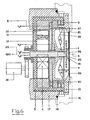
- ein weiteres erfindungsgemässes Beispiel, detaillierter und schematisch im Schnitt dargestellt.
- Fig.7
- ein Beispiel einer gemessenen Kurve für die durchschnittliche Verteilung an einem Substrat über die Targetlebensdauer.
- Fig.8
- das Querschnittsprofil der einen Hälfte eines Targets als Beispiel für die erfindungsgemäss erzielbare Erosion über die Targetlebensdauer.
- Targetdurchmesser: 150 mm
- Targetdicke: 30 mm
- Targetform: im wesentlichen V-förmig gemäss Figur 8 wobei Th die Targetdicke bezeichnet und Rt den Tartetradius in mm und a die Zerstäubungsneufläche 20 definiert
- Targetmaterial: Silber, beziehungsweise Silberlegierung
- Targetausnutzung: > 45%
- Transferfaktor des Targetmaterials: > 45%
- Schichtdickenverteilung: ca. 5 %
- Target-Substratabstand: d=30 mm
- Zerstäubungsgas und Druck: Ar, ca. 10-3 Millibar
- Anzahl CDR-Beschichtungen; > 110'000 / Target
- Substratdurchmesser: 120 mm (CDR)
- Schichtdicke am Substrat: ca. 700 Å
Claims (17)
- Magnetronzerstäubungsquelle mit einem runden Targetkörper (1) dessen Stirnseite eine Zerstäubungsfläche (20, 21) aufweist, mit einem Magnetsystem (2,3,4,5,10,11) enthaltend einen Innenpol (4) und einen diesen ringförmig umgebenden Aussenpol (3), derart dass sich ein Magnetfeld (B) über der Zerstäubungsfläche (20,21) in Form einer geschlossenen tunnelartigen Schleife um die zentrale Quellenachse (6) ausbildet, und dass mindestens ein Teil des Magnetsystems (2,3,4,5,10,11) um die Quellenachse (6) rotierbar gelagert ist und diesen mit Antriebsmittel (30) wirkverbunden ist dadurch gekennzeichnet, dass der ringförmige Aussenpol (3) nicht in gleicher Ebenen mit dem Innenpol (4) liegt und im Randbereich des runden Targetkörpers (1) hochgezogen ist und der rotierbare Magnetsystemteil den zur Achse (6) exzentrisch angeordneten Innenpol (4) aufnimmt und einen zwischen Aussenpol (3) und Innenpol (4) liegenden zweiten Aussenpolteil (11) aufnimmt, derart dass bei Rotation die Tunnelschleife des Magnetfeldes (B) die Zerstäubungsfläche (20,21) exzentrisch überstreicht.
- Quelle nach Anspruch 1 dadurch gekennzeichnet, dass das Magnetsystem (2,3,4,5,10,11) Permanentmagnete enthält, insbesondere vom Typ selten-Erdmagnete wie Kobalt-Samarium enthaltend und/oder Neodym.
- Quelle nach Anspruch 2 dadurch gekennzeichnet, dass das Magnetsystem (2,3,4,5,10,11) ein magnetisches Joch (5,10) aus hochpermeablem Material beinhaltet für den Rückschluss des magnetischen Kreises innerhalb der Quellenanordnung.
- Quelle nach Anspruch 3 dadurch gekennzeichnet, dass das Joch (5,10) zweiteilig konzentrisch ausgebildet ist und einen ersten äusseren stationären Teil (5) und einen zweiten inneren rotierbar gelagerten Teil (10) aufweist.
- Quelle nach Anspruch 4 dadurch gekennzeichnet, dass das innere Jochteil (10) den Innenpol (4) und Aussenpolteil (11) aufnimmt.
- Quelle nach einem der Ansprüche 1 bis 5 dadurch gekennzeichnet, dass mindestens einer der Pole (3,4,11) aus permanentmagnetischem Material bestehen, vorzugsweise alle drei Pole (3,4,11).
- Quelle nach einem der vorhergehenden Ansprüche 1 bis 6 dadurch gekennzeichnet, dass der magnetische Kreis des Magnetsystems so ausgebildet ist, dass die Richtcharakteristik bezüglich der abgestäubten Teilchen der Zerstäubungsfläche (20,21) auf ein davor angeordnetes flaches Substrat (s) während des Zerstäubungsbetriebes über die Lebensdauer des Targetkörpers (1) im.wesentlichen gleich erhalten bleibt.
- Quelle nach einem der vorhergehenden Ansprüche 1 bis 7 dadurch gekennzeichnet, dass die Zerstäubungsfläche (20) mindestens in Teilbereichen konkav ausgebildet ist.
- Quelle nach einem der vorhergehenden Ansprüche 1 bis 8 dadurch gekennzeichnet, dass im Quellenzentrum entlang der Quellenachse (6) eine Zentrumsmaske (16) vorgesehen ist, die den Targetkörper in Richtung zur Substrateben (s) durchdringt und diese elektrisch nicht mit dem Target zusammengeschaltet ist und vorzugsweise eine Gegenelektrode zum Target (1) insbesondere Anode bildet, oder floatend angeordnet ist.
- Quelle nach einem der vorhergehenden Ansprüche 1 bis 9 dadurch gekennzeichnet, dass der Targetkörper (1) die Zentralachse (6), insbesondere die Zentralmaske (16), ringförmig umschliesst und die Zerstäubungsfläche (20) vorzugsweise konkav beziehungsweise rinnenförmig ausgebildet ist, und vorzugsweise im Querschnitt im wesentlichen eine V-förmige Zerstäubungsneufläche (20) aufweist.
- Quelle nach einem der vorhergehenden Ansprüche 1 bis 10 dadurch gekennzeichnet, dass der Aussenpol-Magnet (3) im Bereich der Peripherie des Targetkörpers (1) und der Zerstäubungsfläche (20) angeordnet ist.
- Quelle nach einem der vorhergehenden Ansprüche 1 bis 11 dadurch gekennzeichnet, dass eine Gegenelektrode (15) den Targetkörper (1) im Bereich der Zerstäubungsflächenperipherie (20) umschliesst wobei diese eine Aufnahmeöffnung (28) bildet zur Aufnahme eines Substrates (s).
- Quelle nach Anspruch 12 dadurch gekennzeichnet, dass der grösste Abstand (d) zwischen der Targetneufläche (20) und der Ebenen der Aufnahmeöffnung (28) im Bereich von 20 bis 60 mm liegt, vorzugsweise zwischen 20 bis 40 mm.
- Quelle nach Anspruch 13 dadurch gekennzeichnet, dass die Aufnahmeöffnung (28) Substrate (s) mit einem Durchmesser von 50 bis 150 mm vorzugsweise von 70 bis 150 mm aufnehmen kann.
- Quelle nach einem der Ansprüche 13 bis 14 dadurch gekennzeichnet, dass der Durchmesser der Zerstäubungsfläche (20) grösser ist als der Durchmesser der Aufnahmeöffnung (28), vorzugsweise um bis zu 30%, insbesondere um bis zu 25%.
- Quelle nach einem der Ansprüche 1 bis 15 dadurch gekennzeichnet, dass der Targetkörper (1) aus Metall oder einer Metallegierung besteht, vorzugsweise eines der Metalle Silber, Gold oder Aluminium enthält.
- Verwendung der Zerstäubungsquelle nach einem der Ansprüche 1 bis 16 für das Zerstäubungsbeschichten von Speicherplatten, insbesondere für optische Speicher wie CD's, CDR's, CD-RW's und bevorzugt für DVD's.
Applications Claiming Priority (3)
| Application Number | Priority Date | Filing Date | Title |
|---|---|---|---|
| CH10522001 | 2001-06-12 | ||
| CH105201 | 2001-06-12 | ||
| PCT/CH2002/000285 WO2002101785A1 (de) | 2001-06-12 | 2002-05-30 | Magnetronzerstäubungsquelle |
Publications (2)
| Publication Number | Publication Date |
|---|---|
| EP1399945A1 EP1399945A1 (de) | 2004-03-24 |
| EP1399945B1 true EP1399945B1 (de) | 2005-04-13 |
Family
ID=4554892
Family Applications (1)
| Application Number | Title | Priority Date | Filing Date |
|---|---|---|---|
| EP02727150A Expired - Lifetime EP1399945B1 (de) | 2001-06-12 | 2002-05-30 | Magnetronzerstäubungsquelle |
Country Status (9)
| Country | Link |
|---|---|
| US (2) | US6682637B2 (de) |
| EP (1) | EP1399945B1 (de) |
| JP (1) | JP4371805B2 (de) |
| CN (1) | CN1309002C (de) |
| AT (1) | ATE293283T1 (de) |
| DE (1) | DE50202784D1 (de) |
| ES (1) | ES2237676T3 (de) |
| TW (1) | TWI229138B (de) |
| WO (1) | WO2002101785A1 (de) |
Families Citing this family (27)
| Publication number | Priority date | Publication date | Assignee | Title |
|---|---|---|---|---|
| JP2004514066A (ja) * | 2000-11-27 | 2004-05-13 | ユナキス・トレーディング・アクチェンゲゼルシャフト | 厚さがならい削りされた、rfマグネトロン用ターゲット |
| US7335521B2 (en) * | 2004-07-02 | 2008-02-26 | Oc Oerlikon Balzers Ag | Method for the production of multilayer discs |
| US7267748B2 (en) * | 2004-10-19 | 2007-09-11 | Centre Luxembourgeois De Recherches Pour Le Verre Et La Ceramique S.A. | Method of making coated article having IR reflecting layer with predetermined target-substrate distance |
| KR101255375B1 (ko) * | 2004-12-28 | 2013-04-17 | 가부시키가이샤 알박 | 스퍼터원, 스퍼터 장치, 박막의 제조 방법 |
| US7186319B2 (en) * | 2005-01-05 | 2007-03-06 | Applied Materials, Inc. | Multi-track magnetron exhibiting more uniform deposition and reduced rotational asymmetry |
| DE102005019100B4 (de) * | 2005-04-25 | 2009-02-12 | Steag Hamatech Ag | Magnetsystem für eine Zerstäubungskathode |
| US20060278519A1 (en) * | 2005-06-10 | 2006-12-14 | Leszek Malaszewski | Adaptable fixation for cylindrical magnetrons |
| US8424192B1 (en) | 2005-08-08 | 2013-04-23 | Western Digital (Fremont), Llc | Method for manufacturing a pole for a magnetic recording head |
| RU2448388C2 (ru) | 2006-05-16 | 2012-04-20 | Эрликон Трейдинг Аг, Трюббах | Электродуговой источник и магнитное приспособление |
| US8075593B2 (en) * | 2007-05-01 | 2011-12-13 | Spinal Simplicity Llc | Interspinous implants and methods for implanting same |
| US8142479B2 (en) * | 2007-05-01 | 2012-03-27 | Spinal Simplicity Llc | Interspinous process implants having deployable engagement arms |
| TWI381472B (zh) * | 2008-01-15 | 2013-01-01 | Ulvac Inc | 基板載置台、具備其之濺鍍裝置及成膜方法 |
| US8945184B2 (en) | 2009-03-13 | 2015-02-03 | Spinal Simplicity Llc. | Interspinous process implant and fusion cage spacer |
| US9757164B2 (en) | 2013-01-07 | 2017-09-12 | Spinal Simplicity Llc | Interspinous process implant having deployable anchor blades |
| US9861399B2 (en) | 2009-03-13 | 2018-01-09 | Spinal Simplicity, Llc | Interspinous process implant having a body with a removable end portion |
| JP5343835B2 (ja) * | 2009-12-10 | 2013-11-13 | 日新イオン機器株式会社 | 反射電極構造体及びイオン源 |
| CN102315064B (zh) * | 2010-07-02 | 2014-07-30 | 北京北方微电子基地设备工艺研究中心有限责任公司 | 一种磁控管及应用该磁控管的薄膜沉积处理设备 |
| CN102789938B (zh) * | 2011-05-18 | 2016-06-08 | 北京北方微电子基地设备工艺研究中心有限责任公司 | 一种磁控管、磁控管的制造方法及物理沉积室 |
| CN103177916B (zh) * | 2011-12-20 | 2015-09-02 | 北京北方微电子基地设备工艺研究中心有限责任公司 | 一种磁控管及磁控溅射设备 |
| US10043670B2 (en) * | 2015-10-22 | 2018-08-07 | Applied Materials, Inc. | Systems and methods for low resistivity physical vapor deposition of a tungsten film |
| CN107785219B (zh) * | 2016-08-30 | 2019-10-11 | 北京北方华创微电子装备有限公司 | 一种磁控元件和磁控溅射装置 |
| JP7471236B2 (ja) * | 2018-02-13 | 2024-04-19 | エヴァテック・アーゲー | マグネトロンスパッタリングのための方法および装置 |
| CN110106487B (zh) * | 2019-05-28 | 2020-07-14 | 上海交通大学 | 一种提高靶材使用率的磁控溅射圆形平面靶枪的磁靶 |
| CN111304620A (zh) * | 2020-04-24 | 2020-06-19 | 北京北方华创微电子装备有限公司 | 半导体加工设备及其磁控管机构 |
| US12133664B2 (en) | 2022-12-13 | 2024-11-05 | Spinal Simplicity, Llc | Medical implant |
| CN116426893B (zh) * | 2023-06-13 | 2023-08-18 | 上海陛通半导体能源科技股份有限公司 | 磁控溅射设备及方法 |
| CN120158719B (zh) * | 2025-05-19 | 2025-09-05 | 华晟昇纳米科技(成都)有限公司 | 中心磁场可旋转式靶阴极及磁控溅射镀膜装置 |
Family Cites Families (9)
| Publication number | Priority date | Publication date | Assignee | Title |
|---|---|---|---|---|
| US5126028A (en) * | 1989-04-17 | 1992-06-30 | Materials Research Corporation | Sputter coating process control method and apparatus |
| US4957605A (en) * | 1989-04-17 | 1990-09-18 | Materials Research Corporation | Method and apparatus for sputter coating stepped wafers |
| DE4125110C2 (de) * | 1991-07-30 | 1999-09-09 | Leybold Ag | Magnetron-Zerstäubungskathode für Vakuumbeschichtungsanlagen |
| US5262028A (en) * | 1992-06-01 | 1993-11-16 | Sierra Applied Sciences, Inc. | Planar magnetron sputtering magnet assembly |
| US5496455A (en) * | 1993-09-16 | 1996-03-05 | Applied Material | Sputtering using a plasma-shaping magnet ring |
| ATE130465T1 (de) * | 1994-04-07 | 1995-12-15 | Balzers Hochvakuum | Magnetronzerstäubungsquelle und deren verwendung. |
| CN1067118C (zh) * | 1994-07-08 | 2001-06-13 | 松下电器产业株式会社 | 磁控管溅射装置 |
| US6497796B1 (en) * | 1999-01-05 | 2002-12-24 | Novellus Systems, Inc. | Apparatus and method for controlling plasma uniformity across a substrate |
| US6352629B1 (en) * | 2000-07-10 | 2002-03-05 | Applied Materials, Inc. | Coaxial electromagnet in a magnetron sputtering reactor |
-
2002
- 2002-05-06 TW TW091109353A patent/TWI229138B/zh not_active IP Right Cessation
- 2002-05-30 DE DE50202784T patent/DE50202784D1/de not_active Expired - Lifetime
- 2002-05-30 WO PCT/CH2002/000285 patent/WO2002101785A1/de not_active Ceased
- 2002-05-30 AT AT02727150T patent/ATE293283T1/de not_active IP Right Cessation
- 2002-05-30 CN CNB028119150A patent/CN1309002C/zh not_active Expired - Fee Related
- 2002-05-30 EP EP02727150A patent/EP1399945B1/de not_active Expired - Lifetime
- 2002-05-30 JP JP2003504435A patent/JP4371805B2/ja not_active Expired - Fee Related
- 2002-05-30 ES ES02727150T patent/ES2237676T3/es not_active Expired - Lifetime
- 2002-06-04 US US10/161,862 patent/US6682637B2/en not_active Expired - Lifetime
-
2003
- 2003-11-06 US US10/703,217 patent/US6860977B2/en not_active Expired - Lifetime
Also Published As
| Publication number | Publication date |
|---|---|
| US6860977B2 (en) | 2005-03-01 |
| ATE293283T1 (de) | 2005-04-15 |
| EP1399945A1 (de) | 2004-03-24 |
| JP4371805B2 (ja) | 2009-11-25 |
| HK1066094A1 (en) | 2005-03-11 |
| US6682637B2 (en) | 2004-01-27 |
| ES2237676T3 (es) | 2005-08-01 |
| DE50202784D1 (de) | 2005-05-19 |
| JP2005505686A (ja) | 2005-02-24 |
| US20040149565A1 (en) | 2004-08-05 |
| WO2002101785A1 (de) | 2002-12-19 |
| CN1309002C (zh) | 2007-04-04 |
| US20030136671A1 (en) | 2003-07-24 |
| CN1516888A (zh) | 2004-07-28 |
| TWI229138B (en) | 2005-03-11 |
Similar Documents
| Publication | Publication Date | Title |
|---|---|---|
| EP1399945A1 (de) | Magnetronzerstäubungsquelle | |
| DE69926634T2 (de) | Profiliertes sputtertarget | |
| DE3506227A1 (de) | Anordnung zur beschichtung von substraten mittels kathodenzerstaeubung | |
| EP0493647B1 (de) | Zerstäubungskathode für die Beschichtung von Substraten in Katodenzerstäubungsanlagen | |
| DE69122757T2 (de) | Vorrichtung zum magnetronsputtern mit geschlitzter zylindrischer hohlkathode | |
| DE69605840T2 (de) | Magnetron Zerstäubungssystem | |
| EP0914495B1 (de) | Targetanordnung mit einer kreisförmigen platte | |
| EP1254970A1 (de) | Magnetronsputterquelle mit mehrteiligem Target | |
| WO1998028778A1 (de) | Vorrichtung zur kathodenzerstäubung | |
| EP0676791B1 (de) | Magnetronzerstäubungsquelle und deren Verwendung | |
| EP2466614A2 (de) | Arcquelle und Magnetanordnung | |
| CH683777A5 (de) | Ortsfeste Magnetron-Zerstäubungskathode für Vakuumbeschichtungsanlagen. | |
| EP1144714A1 (de) | Verfahren und einrichtung zum beschichten von substraten mittels bipolarer puls-magnetron-zerstäubung und deren anwendung | |
| DE4202349C2 (de) | Vorrichtung zur Kathodenzerstäubung | |
| DE112009003766T5 (de) | Sputter-Vorrichtung und Sputter-Verfahren | |
| DE10196150B4 (de) | Magnetron-Sputtervorrichtung und Verfahren zum Steuern einer solchen Vorrichtung | |
| DE69017555T2 (de) | Verfahren und Vorrichtung zum Sputterauftragen von Filmen. | |
| DE69128544T2 (de) | Verfahren und vorrichtung zur sputtenbeschichtung mit rotierender magnetischer kathode | |
| DE10004824B4 (de) | Verfahren zur Herstellung von Substraten, Magnetronquelle, Sputterbeschichtungskammer und Verwendung des Verfahrens | |
| DE19617155B4 (de) | Sputterbeschichtungsstation, Verfahren zur Herstellung sputterbeschichteter Werkstücke und Verwendung der Station oder des Verfahrens zur Beschichtung scheibenförmiger Substrate | |
| DE10215369A1 (de) | Kathodenzerstäubungsgerät zur Ausbildung eines Metallfilms unter Verwendung eines Magnetfeldes | |
| DE19639240C2 (de) | Magnetronzerstäubungsquelle und deren Verwendung | |
| EP0955667B1 (de) | Target für eine Kathodenzerstäubungsvorrichtung zur Herstellung dünner Schichten | |
| DE102005019100B4 (de) | Magnetsystem für eine Zerstäubungskathode | |
| EP4131332A1 (de) | Mehrfach-sputtertarget |
Legal Events
| Date | Code | Title | Description |
|---|---|---|---|
| PUAI | Public reference made under article 153(3) epc to a published international application that has entered the european phase |
Free format text: ORIGINAL CODE: 0009012 |
|
| 17P | Request for examination filed |
Effective date: 20040112 |
|
| AK | Designated contracting states |
Kind code of ref document: A1 Designated state(s): AT BE CH CY DE DK ES FI FR GB GR IE IT LI LU MC NL PT SE TR |
|
| AX | Request for extension of the european patent |
Extension state: AL LT LV MK RO SI |
|
| RIN1 | Information on inventor provided before grant (corrected) |
Inventor name: KADLEC, STANISLAV Inventor name: GRUENENFELDER, PIUS Inventor name: EISENHAMMER, THOMAS Inventor name: KRASSNITZER, SIEGFIED Inventor name: HEINZ, BERND Inventor name: HAAG, WALTER Inventor name: DUBS, MARTIN |
|
| GRAP | Despatch of communication of intention to grant a patent |
Free format text: ORIGINAL CODE: EPIDOSNIGR1 |
|
| GRAA | (expected) grant |
Free format text: ORIGINAL CODE: 0009210 |
|
| GRAS | Grant fee paid |
Free format text: ORIGINAL CODE: EPIDOSNIGR3 |
|
| AK | Designated contracting states |
Kind code of ref document: B1 Designated state(s): AT BE CH CY DE DK ES FI FR GB GR IE IT LI LU MC NL PT SE TR |
|
| PG25 | Lapsed in a contracting state [announced via postgrant information from national office to epo] |
Ref country code: TR Free format text: LAPSE BECAUSE OF FAILURE TO SUBMIT A TRANSLATION OF THE DESCRIPTION OR TO PAY THE FEE WITHIN THE PRESCRIBED TIME-LIMIT Effective date: 20050413 Ref country code: FI Free format text: LAPSE BECAUSE OF FAILURE TO SUBMIT A TRANSLATION OF THE DESCRIPTION OR TO PAY THE FEE WITHIN THE PRESCRIBED TIME-LIMIT Effective date: 20050413 |
|
| REG | Reference to a national code |
Ref country code: GB Ref legal event code: FG4D Free format text: NOT ENGLISH |
|
| REG | Reference to a national code |
Ref country code: CH Ref legal event code: EP |
|
| GBT | Gb: translation of ep patent filed (gb section 77(6)(a)/1977) |
Effective date: 20050413 |
|
| PGFP | Annual fee paid to national office [announced via postgrant information from national office to epo] |
Ref country code: AT Payment date: 20050511 Year of fee payment: 4 |
|
| REG | Reference to a national code |
Ref country code: IE Ref legal event code: FG4D Free format text: LANGUAGE OF EP DOCUMENT: GERMAN |
|
| REF | Corresponds to: |
Ref document number: 50202784 Country of ref document: DE Date of ref document: 20050519 Kind code of ref document: P |
|
| PG25 | Lapsed in a contracting state [announced via postgrant information from national office to epo] |
Ref country code: CY Free format text: LAPSE BECAUSE OF FAILURE TO SUBMIT A TRANSLATION OF THE DESCRIPTION OR TO PAY THE FEE WITHIN THE PRESCRIBED TIME-LIMIT Effective date: 20050530 |
|
| PG25 | Lapsed in a contracting state [announced via postgrant information from national office to epo] |
Ref country code: MC Free format text: LAPSE BECAUSE OF NON-PAYMENT OF DUE FEES Effective date: 20050531 |
|
| PGFP | Annual fee paid to national office [announced via postgrant information from national office to epo] |
Ref country code: LU Payment date: 20050531 Year of fee payment: 4 |
|
| PG25 | Lapsed in a contracting state [announced via postgrant information from national office to epo] |
Ref country code: GR Free format text: LAPSE BECAUSE OF FAILURE TO SUBMIT A TRANSLATION OF THE DESCRIPTION OR TO PAY THE FEE WITHIN THE PRESCRIBED TIME-LIMIT Effective date: 20050713 Ref country code: DK Free format text: LAPSE BECAUSE OF FAILURE TO SUBMIT A TRANSLATION OF THE DESCRIPTION OR TO PAY THE FEE WITHIN THE PRESCRIBED TIME-LIMIT Effective date: 20050713 |
|
| PGFP | Annual fee paid to national office [announced via postgrant information from national office to epo] |
Ref country code: BE Payment date: 20050714 Year of fee payment: 4 |
|
| REG | Reference to a national code |
Ref country code: SE Ref legal event code: TRGR |
|
| REG | Reference to a national code |
Ref country code: ES Ref legal event code: FG2A Ref document number: 2237676 Country of ref document: ES Kind code of ref document: T3 |
|
| PG25 | Lapsed in a contracting state [announced via postgrant information from national office to epo] |
Ref country code: PT Free format text: LAPSE BECAUSE OF FAILURE TO SUBMIT A TRANSLATION OF THE DESCRIPTION OR TO PAY THE FEE WITHIN THE PRESCRIBED TIME-LIMIT Effective date: 20050913 |
|
| PLBE | No opposition filed within time limit |
Free format text: ORIGINAL CODE: 0009261 |
|
| STAA | Information on the status of an ep patent application or granted ep patent |
Free format text: STATUS: NO OPPOSITION FILED WITHIN TIME LIMIT |
|
| ET | Fr: translation filed | ||
| 26N | No opposition filed |
Effective date: 20060116 |
|
| PG25 | Lapsed in a contracting state [announced via postgrant information from national office to epo] |
Ref country code: AT Free format text: LAPSE BECAUSE OF NON-PAYMENT OF DUE FEES Effective date: 20060530 |
|
| PG25 | Lapsed in a contracting state [announced via postgrant information from national office to epo] |
Ref country code: BE Free format text: LAPSE BECAUSE OF NON-PAYMENT OF DUE FEES Effective date: 20060531 |
|
| REG | Reference to a national code |
Ref country code: CH Ref legal event code: PFA Owner name: OC OERLIKON BALZERS AG Free format text: UNAXIS BALZERS AKTIENGESELLSCHAFT# #9496 BALZERS (LI) -TRANSFER TO- OC OERLIKON BALZERS AG#PATENTABTEILUNG POSTFACH 1000#9496 BALZERS (LI) |
|
| BERE | Be: lapsed |
Owner name: *UNAXIS BALZERS A.G. Effective date: 20060531 |
|
| PG25 | Lapsed in a contracting state [announced via postgrant information from national office to epo] |
Ref country code: LU Free format text: LAPSE BECAUSE OF NON-PAYMENT OF DUE FEES Effective date: 20060530 |
|
| PGFP | Annual fee paid to national office [announced via postgrant information from national office to epo] |
Ref country code: ES Payment date: 20100611 Year of fee payment: 9 |
|
| PGFP | Annual fee paid to national office [announced via postgrant information from national office to epo] |
Ref country code: SE Payment date: 20100510 Year of fee payment: 9 |
|
| REG | Reference to a national code |
Ref country code: SE Ref legal event code: EUG |
|
| PG25 | Lapsed in a contracting state [announced via postgrant information from national office to epo] |
Ref country code: SE Free format text: LAPSE BECAUSE OF NON-PAYMENT OF DUE FEES Effective date: 20110531 |
|
| REG | Reference to a national code |
Ref country code: ES Ref legal event code: FD2A Effective date: 20130605 |
|
| PG25 | Lapsed in a contracting state [announced via postgrant information from national office to epo] |
Ref country code: ES Free format text: LAPSE BECAUSE OF NON-PAYMENT OF DUE FEES Effective date: 20110531 |
|
| REG | Reference to a national code |
Ref country code: CH Ref legal event code: PFA Owner name: OERLIKON ADVANCED TECHNOLOGIES AG, LI Free format text: FORMER OWNER: OC OERLIKON BALZERS AG, LI |
|
| REG | Reference to a national code |
Ref country code: FR Ref legal event code: TP Owner name: OERLIKON ADVANCED TECHNOLOGIES AG, LI Effective date: 20140627 |
|
| REG | Reference to a national code |
Ref country code: GB Ref legal event code: 732E Free format text: REGISTERED BETWEEN 20140710 AND 20140716 |
|
| REG | Reference to a national code |
Ref country code: NL Ref legal event code: TD Effective date: 20141022 Ref country code: NL Ref legal event code: SD Effective date: 20141022 |
|
| REG | Reference to a national code |
Ref country code: DE Ref legal event code: R081 Ref document number: 50202784 Country of ref document: DE Owner name: OERLIKON ADVANCED TECHNOLOGIES AG, LI Free format text: FORMER OWNER: OC OERLIKON BALZERS AG, BALZERS, LI Effective date: 20141216 |
|
| REG | Reference to a national code |
Ref country code: FR Ref legal event code: PLFP Year of fee payment: 15 |
|
| REG | Reference to a national code |
Ref country code: FR Ref legal event code: PLFP Year of fee payment: 16 |
|
| REG | Reference to a national code |
Ref country code: FR Ref legal event code: PLFP Year of fee payment: 17 |
|
| PGFP | Annual fee paid to national office [announced via postgrant information from national office to epo] |
Ref country code: CH Payment date: 20180508 Year of fee payment: 17 Ref country code: DE Payment date: 20180515 Year of fee payment: 17 Ref country code: IE Payment date: 20180509 Year of fee payment: 17 |
|
| PGFP | Annual fee paid to national office [announced via postgrant information from national office to epo] |
Ref country code: NL Payment date: 20180514 Year of fee payment: 17 Ref country code: IT Payment date: 20180522 Year of fee payment: 17 Ref country code: FR Payment date: 20180411 Year of fee payment: 17 |
|
| PGFP | Annual fee paid to national office [announced via postgrant information from national office to epo] |
Ref country code: GB Payment date: 20180530 Year of fee payment: 17 |
|
| REG | Reference to a national code |
Ref country code: CH Ref legal event code: PUE Owner name: EVATEC AG, CH Free format text: FORMER OWNER: OERLIKON ADVANCED TECHNOLOGIES AG, LI |
|
| REG | Reference to a national code |
Ref country code: DE Ref legal event code: R081 Ref document number: 50202784 Country of ref document: DE Owner name: EVATEC AG, CH Free format text: FORMER OWNER: OERLIKON ADVANCED TECHNOLOGIES AG, BALZERS, LI |
|
| REG | Reference to a national code |
Ref country code: DE Ref legal event code: R081 Ref document number: 50202784 Country of ref document: DE Owner name: EVATEC AG, CH Free format text: FORMER OWNER: EVATEC ADVANCED TECHNOLOGIES AG, BALZERS, LI |
|
| REG | Reference to a national code |
Ref country code: GB Ref legal event code: 732E Free format text: REGISTERED BETWEEN 20190321 AND 20190327 Ref country code: NL Ref legal event code: HC Owner name: EVATEC ADVANCED TECHNOLOGIES AG; LI Free format text: DETAILS ASSIGNMENT: CHANGE OF OWNER(S), CHANGE OF OWNER(S) NAME; FORMER OWNER NAME: OERLIKON ADVANCED TECHNOLOGIES AG Effective date: 20190211 Ref country code: NL Ref legal event code: PD Owner name: EVATEC AG; CH Free format text: DETAILS ASSIGNMENT: CHANGE OF OWNER(S), ASSIGNMENT; FORMER OWNER NAME: EVATEC ADVANCED TECHNOLOGIES AG Effective date: 20190211 |
|
| REG | Reference to a national code |
Ref country code: DE Ref legal event code: R119 Ref document number: 50202784 Country of ref document: DE |
|
| REG | Reference to a national code |
Ref country code: CH Ref legal event code: PL |
|
| REG | Reference to a national code |
Ref country code: NL Ref legal event code: MM Effective date: 20190601 |
|
| GBPC | Gb: european patent ceased through non-payment of renewal fee |
Effective date: 20190530 |
|
| PG25 | Lapsed in a contracting state [announced via postgrant information from national office to epo] |
Ref country code: LI Free format text: LAPSE BECAUSE OF NON-PAYMENT OF DUE FEES Effective date: 20190531 Ref country code: CH Free format text: LAPSE BECAUSE OF NON-PAYMENT OF DUE FEES Effective date: 20190531 |
|
| PG25 | Lapsed in a contracting state [announced via postgrant information from national office to epo] |
Ref country code: IT Free format text: LAPSE BECAUSE OF NON-PAYMENT OF DUE FEES Effective date: 20190530 Ref country code: IE Free format text: LAPSE BECAUSE OF NON-PAYMENT OF DUE FEES Effective date: 20190530 Ref country code: GB Free format text: LAPSE BECAUSE OF NON-PAYMENT OF DUE FEES Effective date: 20190530 Ref country code: DE Free format text: LAPSE BECAUSE OF NON-PAYMENT OF DUE FEES Effective date: 20191203 Ref country code: NL Free format text: LAPSE BECAUSE OF NON-PAYMENT OF DUE FEES Effective date: 20190601 |
|
| PG25 | Lapsed in a contracting state [announced via postgrant information from national office to epo] |
Ref country code: FR Free format text: LAPSE BECAUSE OF NON-PAYMENT OF DUE FEES Effective date: 20190531 |