EP1398570B1 - Can combustor for a gas turbine engine - Google Patents
Can combustor for a gas turbine engine Download PDFInfo
- Publication number
- EP1398570B1 EP1398570B1 EP03076668A EP03076668A EP1398570B1 EP 1398570 B1 EP1398570 B1 EP 1398570B1 EP 03076668 A EP03076668 A EP 03076668A EP 03076668 A EP03076668 A EP 03076668A EP 1398570 B1 EP1398570 B1 EP 1398570B1
- Authority
- EP
- European Patent Office
- Prior art keywords
- burners
- combustor
- fuel
- stage
- gas turbine
- Prior art date
- Legal status (The legal status is an assumption and is not a legal conclusion. Google has not performed a legal analysis and makes no representation as to the accuracy of the status listed.)
- Expired - Lifetime
Links
- 239000000446 fuel Substances 0.000 claims description 66
- 238000002485 combustion reaction Methods 0.000 claims description 50
- 239000007789 gas Substances 0.000 description 34
- 239000003570 air Substances 0.000 description 16
- 239000000567 combustion gas Substances 0.000 description 5
- IJGRMHOSHXDMSA-UHFFFAOYSA-N Atomic nitrogen Chemical compound N#N IJGRMHOSHXDMSA-UHFFFAOYSA-N 0.000 description 4
- 238000009826 distribution Methods 0.000 description 4
- 238000010304 firing Methods 0.000 description 4
- 238000000926 separation method Methods 0.000 description 4
- 230000008859 change Effects 0.000 description 3
- 239000000203 mixture Substances 0.000 description 3
- 239000012080 ambient air Substances 0.000 description 2
- 238000009792 diffusion process Methods 0.000 description 2
- 230000000694 effects Effects 0.000 description 2
- 230000006872 improvement Effects 0.000 description 2
- VNWKTOKETHGBQD-UHFFFAOYSA-N methane Chemical compound C VNWKTOKETHGBQD-UHFFFAOYSA-N 0.000 description 2
- 229910052757 nitrogen Inorganic materials 0.000 description 2
- 230000010349 pulsation Effects 0.000 description 2
- UGFAIRIUMAVXCW-UHFFFAOYSA-N Carbon monoxide Chemical compound [O+]#[C-] UGFAIRIUMAVXCW-UHFFFAOYSA-N 0.000 description 1
- 230000002411 adverse Effects 0.000 description 1
- 229910002091 carbon monoxide Inorganic materials 0.000 description 1
- 238000010586 diagram Methods 0.000 description 1
- 239000006185 dispersion Substances 0.000 description 1
- 238000006073 displacement reaction Methods 0.000 description 1
- 239000000295 fuel oil Substances 0.000 description 1
- 229930195733 hydrocarbon Natural products 0.000 description 1
- 150000002430 hydrocarbons Chemical class 0.000 description 1
- 230000003993 interaction Effects 0.000 description 1
- 239000007788 liquid Substances 0.000 description 1
- 238000004519 manufacturing process Methods 0.000 description 1
- 238000000034 method Methods 0.000 description 1
- 239000003345 natural gas Substances 0.000 description 1
- 238000011084 recovery Methods 0.000 description 1
- 230000009467 reduction Effects 0.000 description 1
- 230000004044 response Effects 0.000 description 1
- 238000011144 upstream manufacturing Methods 0.000 description 1
Images
Classifications
-
- F—MECHANICAL ENGINEERING; LIGHTING; HEATING; WEAPONS; BLASTING
- F23—COMBUSTION APPARATUS; COMBUSTION PROCESSES
- F23R—GENERATING COMBUSTION PRODUCTS OF HIGH PRESSURE OR HIGH VELOCITY, e.g. GAS-TURBINE COMBUSTION CHAMBERS
- F23R3/00—Continuous combustion chambers using liquid or gaseous fuel
- F23R3/42—Continuous combustion chambers using liquid or gaseous fuel characterised by the arrangement or form of the flame tubes or combustion chambers
- F23R3/46—Combustion chambers comprising an annular arrangement of several essentially tubular flame tubes within a common annular casing or within individual casings
-
- F—MECHANICAL ENGINEERING; LIGHTING; HEATING; WEAPONS; BLASTING
- F23—COMBUSTION APPARATUS; COMBUSTION PROCESSES
- F23R—GENERATING COMBUSTION PRODUCTS OF HIGH PRESSURE OR HIGH VELOCITY, e.g. GAS-TURBINE COMBUSTION CHAMBERS
- F23R3/00—Continuous combustion chambers using liquid or gaseous fuel
- F23R3/28—Continuous combustion chambers using liquid or gaseous fuel characterised by the fuel supply
- F23R3/34—Feeding into different combustion zones
- F23R3/346—Feeding into different combustion zones for staged combustion
-
- F—MECHANICAL ENGINEERING; LIGHTING; HEATING; WEAPONS; BLASTING
- F23—COMBUSTION APPARATUS; COMBUSTION PROCESSES
- F23C—METHODS OR APPARATUS FOR COMBUSTION USING FLUID FUEL OR SOLID FUEL SUSPENDED IN A CARRIER GAS OR AIR
- F23C2201/00—Staged combustion
- F23C2201/20—Burner staging
Definitions
- This invention relates to the field of gas turbine engines and, in particular, to gas turbine engines having a can annular combustor.
- Gas turbine engines are known to include a compressor for compressing air; a combustor for producing a hot gas by burning fuel in the presence of the compressed air produced by the compressor, and a turbine for expanding the hot gas to extract shaft power.
- the combustion process in many older gas turbine engines is dominated by diffusion flames burning at or near stoichiometric conditions with flame temperatures exceeding 1649°C (3,000 °F). Such combustion will produce a high level of oxides of nitrogen (NOx).
- Current emissions regulations have greatly reduced the allowable levels of NOx emissions.
- Lean premixed combustion has been developed to reduce the peak flame temperatures and to correspondingly reduce the production of NOx in gas turbine engines.
- Gas turbines having an annular combustion chamber include a plurality of burners disposed in one or more concentric rings for providing fuel into a single toroidal annulus.
- United States patent 5,400,587 describes one such annular combustion chamber design.
- Annular combustion chamber dynamics are generally dominated by circumferential pressure pulsation modes between the plurality of burners.
- gas turbines having can annular combustion chambers include a plurality of individual can combustors wherein the combustion process in each can is relatively isolated from interaction with the combustion process of adjacent cans.
- Can annular combustion chamber dynamics are generally dominated by axial pressure pulsation modes within the individual cans.
- Staging is the delivery of fuel to the combustion chamber through at least two separately controllable fuel supply systems or stages including separate fuel nozzles or sets of fuel nozzles. As the power level of the machine is increased, the amount of fuel supplied through each stage is increased to achieve a desired power level.
- a two-stage can annular combustor is described in United States patent 4,265,085 .
- the combustor of the '085 patent includes a primary stage delivering fuel to a central region of the combustion chamber and a secondary stage delivering fuel to an annular region of the combustion chamber surrounding the central region.
- the primary stage is a fuel-rich core wherein stoichiometry can be optimized.
- United States patent 5,974,781 describes an axially staged hybrid can-annular combustor wherein the premixers for two stages are positioned at different axial locations along the axial flow path of the combustion air.
- United States patent 5,307,621 describes a method of controlling combustion using an asymmetric whirl combustion pattern.
- US 5 339 635 A discloses a gas turbine combustor of the pre-mixed combustion system in which the pre-mixed fuel and the air are combusted.
- the gas turbine combustor comprises main cylindrical nozzles provided in the end wall on the upstream side of a cylindrical combustion chamber, auxiliary nozzles formed to surround the main nozzles, a main pre-mixed gas supply for supplying a pre-mixed gas to the main nozzles, and an auxiliary pre-mixed gas supply for supplying a pre-mixed gas having a fuel/air ratio smaller than that of the main pre-mixed gas to the auxiliary nozzles, and wherein it is allowed to stably burn a lean pre-mixed gas having a fuel/air ratio of greater than one from a low-load condition through and up to a high-load condition of the gas turbine.
- JP 5 215 338 A NOx is reduced and flame holding performance is improved in a gas turbine device in which gas fuel and liquid fuel are used.
- a pilot nozzle is arranged on a central line of an inner cylinder.
- main nozzles comprising first and second groups of pluralities of nozzles are arranged on each of pitch circles having different diameters.
- Fuel is mixed with air at each of the main nozzles of the groups so as to perform pre-mixing and combustion. Dispersion and combustion is carried out at the pilot nozzle and then the nozzle acts as a flame holder for the pre-mixing flame.
- the group of main nozzles to be used is properly selected in response to load, thereby reduction of NOx can be realized over a range from partial load to full load
- US 4 344 280 A which is considered as closest prior art, discloses a combustor of a gas turbine including fuel distributing and supplying means including a plurality of sets of fuel nozzles arranged circularly on the head of the combustor and each fuel nozzle being provided with a combustion primary air swirler, and a plurality of fuel supply systems each connected to one fuel nozzle or a plurality of fuel nozzles.
- One set of fuel nozzles is located inside another set of fuel nozzles and projects further inwardly into the interior of the combustor.
- the number of the fuel supply systems handling a supply of fuel can be increased or reduced depending on the volume of fuel.
- a can combustor for a gas turbine engine comprising: a first stage comprising a first plurality of N burners arranged symmetrically around a longitudinal centerline of a combustion chamber and angularly separated from each other by an angle of 360/N degrees, the first plurality of burners being supplied by a first independently controllable fuel supply; a second stage comprising a second plurality of N burners arranged symmetrically around the longitudinal centerline of the combustion chamber and angularly separated from each other by an angle of 360/N degrees, the second plurality of burners being supplied by a second independently controllable fuel supply; wherein each burner of the second stage is interposed between a pair of angularly neighboring burners of the first stage at an angular location that is other than angularly midway between the pair of angularly neighboring burners of the first stage.
- the first plurality of burners may be spaced from the longitudinal centerline at a first radial distance; and the second plurality of burners may be spaced from the longitudinal centerline at a second radial distance different than the first radial distance.
- the present invention extends to a gas turbine engine comprising: a compressor for supplying compressed air; a can annular combustor for burning fuel in the compressed air to produce a hot gas; and a turbine for expanding the hot gas; wherein the can annular combustor further comprises a plurality of can combustors each comprising a can combustor according to the present invention.
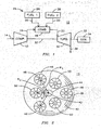
- FIG. 1 illustrates a gas turbine engine 10 having a compressor 12 for receiving a flow of filtered ambient air 14 and for producing a flow of compressed air 16.
- the compressed air 16 is received by a combustor 18 of the can annular type where it is used to burn a flow of a combustible fuel 20, such as natural gas or fuel oil for example, to produce a flow of hot combustion gas 22.
- the fuel 20 is supplied by a fuel supply apparatus 24 capable of providing two independently controllable stages of fuel flow from a first stage fuel supply 26 and a second stage fuel supply 28.
- the hot combustion gas 22 is received by a turbine 30 where it is expanded to extract mechanical shaft power.
- a common shaft 32 interconnects the turbine 30 with the compressor 12 as well as an electrical generator 34 to provide mechanical power for compressing the ambient air 14 and for producing electrical power, respectively.
- the expanded combustion gas 36 may be exhausted directly to the atmosphere or it may be routed through additional heat recovery systems (not shown).
- FIG. 2 is a partial sectional view of just one of the can combustors 19 contained within the can annular combustor 18 according to the invention.
- FIG. 2 illustrates a section taken perpendicular to the direction of flow of the hot combustion gas 22 through the can combustor 19.
- Combustor can 19 includes an annular member 38 extending from a base plate 39 and defining a combustion chamber 40 having a longitudinal centerline 42.
- a pilot burner 44 may be located at the centerline location, although such a pilot burner may not be used for all applications.
- Combustor 18 also includes a first plurality of burners 46 disposed in a symmetrical ring at a first radial distance R 1 around the centerline 42.
- the distance R 1 is measured from the longitudinal centerline 42 of the combustion chamber 40 to the centerline 48 of the respective burner 46.
- the centers of all of the first plurality of burners 46 are located on a circle having a radius of R 1 about the centerline 42.
- Can combustor 19 also includes a second plurality of burners 50 disposed in a symmetrical ring around the centerline 42 at a second radial distance R 2 .
- R 2 may be equal to or greater than the first radial distance R 1 as will be described more fully below.
- Burners 46, 50 may be any design known in the art and are preferably premix burners.
- the first plurality of burners 46 is connected to the first stage fuel supply 26 and the second plurality of burners 50 is connected to the second stage fuel supply 28 to form a two-stage burner. It is also possible to divide the six burners into three or more fuel stages to provide additional degrees of control flexibility, although it is recognized that additional fuel stages may be expensive and would generally not be used unless necessary. Furthermore, the number of fuel stages should be no more than the number of burners divided by 2 or the combustion will become asymmetric. If provided, the pilot burner 44 may be connected to a separate pilot fuel supply (not shown). The pilot burner 44 may be a premix or diffusion burner.
- the angular separation between neighboring burners 46, 50 is 360/2N° or 60 degrees.
- the relative clocking between the two stages of burners 46, 50 is selected so that an angular separation between burners of the first plurality of burners 46 and neighboring burners of the second plurality of burners 50 is an angle not equal to 360/2N°.
- FIG. 2 illustrates that can combustor 19 has its first stage burners 46 disposed at a different radius R 1 than the radius R 2 of the second stage burners 50.
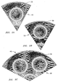
- FIGs. 3A-3C illustrate these differences and how these differences may be used to control the combustion process to avoid instabilities.
- FIG. 3A illustrates a calculated temperature of the hot combustion gas 22 across a plane located just downstream from burner 46 located at a distance R 1 away from centerline 42.
- the darkness of the shading in this figure correlates to the temperature.
- FIG. 3B The results of a similar calculation for a burner 50 under the same firing conditions but located at a distance R 2 away from centerline 42 are illustrated in FIG. 3B .
- R 2 is greater than R 1 .
- the same shading represents the same temperature in each of these Figures.
- a comparison of FIG. 3A to FIG. 3B reveals that the distance of the burner from the centerline 42 affects the temperature distribution within the combustion chamber 40.
- FIGs. 3A, 3B and 3C illustrates the temperature distribution that will result when firing both of two neighboring burners 46, 50 located at respective dissimilar radii of R 1 and R 2 .
- This temperature distribution will change as the relative fuel flow rates are changed between the burners 46, 50.
- the combustion in combustion chamber 40 will remain symmetrical about the centerline 42 regardless of whether only the first stage 46 is fueled, or if only the second stage 50 is fueled, or if both the first and second stages 46, 50 are fueled.
- the temperature distributions of FIGs. 3A, 3B and 3C reveal that there is a difference in the combustion process among these three fueling configurations, and that difference can be exploited as a degree of control over the combustion process to optimize one or more combustion parameters under various operating conditions. This differs from some prior art can combustors wherein the burners of all stages are located at the same radial distance and wherein all stages respond identically to changes in the rate of fuel delivery.
- a further degree of control is developed in the can combustor 19 of FIG. 2 by providing an uneven clocking between the first and second stages 46, 50.
- the angular distance between neighboring nozzles is a constant value of 360/2N degrees.
- angles A and B of FIG. 2 are equal.
- the second plurality of burners 50 at an angular location other than midway between respective burners 46, an angular displacement other than 360/2N degrees is selected. In this case, angles A and B of FIG. 2 are unequal.
- the angle between adjacent burners may be 360/2N° plus or minus no more than 5 degrees or 360/2N° plus or minus no more than10 degrees in two alternative embodiments.
- the combustion is still symmetric as long as all burners of a particular stage move by the same amount.
- Such uneven angular clocking will provide a degree of control that is responsive to the relative fuel flow rates provided to the two stages 46, 50. This effect can be used separately or it can be combined with the above-described effect of providing second stage burners 50 at a different radius than the first stage burners 46.
- the can combustor 19 will behave differently when there is a change in the fuel bias between stages; i.e. providing X% fuel through first stage 46 and Y% fuel through second stage 50 will result in combustion conditions that are different than providing Y% fuel through first stage 46 and X% fuel through second stage 50.
- each stage behaves the same as the other stage.
- the two stages of the present invention will act differently to provide additional control possibilities for suppressing combustion dynamics. This improvement in control flexibility is provided without the necessity for providing an additional fuel stage.
- novel configurations described herein do not change the bulk firing temperature for any particular fuelling level when compared to a prior art can annular combustor. Rather, the aim is to create as many different modes of behavior as possible from a given number of fuel stages. For combustors that hold flame on the base plate 39, it is also possible to alter the flame holding zones on the base plate by fuel stage biasing in the can combustor 19 of FIG. 2 .
Landscapes
- Engineering & Computer Science (AREA)
- Chemical & Material Sciences (AREA)
- Combustion & Propulsion (AREA)
- Mechanical Engineering (AREA)
- General Engineering & Computer Science (AREA)
- Manufacture, Treatment Of Glass Fibers (AREA)
Description
- This invention relates to the field of gas turbine engines and, in particular, to gas turbine engines having a can annular combustor.
- Gas turbine engines are known to include a compressor for compressing air; a combustor for producing a hot gas by burning fuel in the presence of the compressed air produced by the compressor, and a turbine for expanding the hot gas to extract shaft power. The combustion process in many older gas turbine engines is dominated by diffusion flames burning at or near stoichiometric conditions with flame temperatures exceeding 1649°C (3,000 °F). Such combustion will produce a high level of oxides of nitrogen (NOx). Current emissions regulations have greatly reduced the allowable levels of NOx emissions. Lean premixed combustion has been developed to reduce the peak flame temperatures and to correspondingly reduce the production of NOx in gas turbine engines. In a premixed combustion process, fuel and air are premixed in a premixing section of the combustor. The fuel-air mixture is then introduced into a combustion chamber where it is burned. United States patent
6,082,111 describes a gas turbine engine utilizing a can annular premix combustor design. Multiple premixers are positioned in a ring to provide a premixed fuel/air mixture to a combustion chamber. A pilot fuel nozzle is located at the center of the ring to provide a flow of pilot fuel to the combustion chamber. - The design of a gas turbine combustor is complicated by the necessity for the gas turbine engine to operate reliably with a low level of emissions at a variety of power levels. High power operation at high firing temperatures tends to increase the generation of oxides of nitrogen. Low power operation at lower combustion temperatures tends to increase the generation of carbon monoxide and unburned hydrocarbons due to incomplete combustion of the fuel. Under all operating conditions, it is important to ensure the stability of the flame to avoid unexpected flameout, damaging levels of acoustic vibration, and damaging flashback of the flame from the combustion chamber into the fuel premix section of the combustor. A relatively rich fuel/air mixture will improve the stability of the combustion process but will have an adverse affect on the level of emissions. A careful balance must be achieved among these various constraints in order to provide a reliable machine capable of satisfying very strict modern emissions regulations.
- Dynamics concerns vary among the different types of combustor designs. Gas turbines having an annular combustion chamber include a plurality of burners disposed in one or more concentric rings for providing fuel into a single toroidal annulus. United States patent
5,400,587 describes one such annular combustion chamber design. Annular combustion chamber dynamics are generally dominated by circumferential pressure pulsation modes between the plurality of burners. In contrast, gas turbines having can annular combustion chambers include a plurality of individual can combustors wherein the combustion process in each can is relatively isolated from interaction with the combustion process of adjacent cans. Can annular combustion chamber dynamics are generally dominated by axial pressure pulsation modes within the individual cans. - Staging is the delivery of fuel to the combustion chamber through at least two separately controllable fuel supply systems or stages including separate fuel nozzles or sets of fuel nozzles. As the power level of the machine is increased, the amount of fuel supplied through each stage is increased to achieve a desired power level. A two-stage can annular combustor is described in United States patent
4,265,085 . The combustor of the '085 patent includes a primary stage delivering fuel to a central region of the combustion chamber and a secondary stage delivering fuel to an annular region of the combustion chamber surrounding the central region. The primary stage is a fuel-rich core wherein stoichiometry can be optimized. United States patent5,974,781 describes an axially staged hybrid can-annular combustor wherein the premixers for two stages are positioned at different axial locations along the axial flow path of the combustion air. United States patent5,307,621 describes a method of controlling combustion using an asymmetric whirl combustion pattern. -
US 5 339 635 A discloses a gas turbine combustor of the pre-mixed combustion system in which the pre-mixed fuel and the air are combusted. The gas turbine combustor comprises main cylindrical nozzles provided in the end wall on the upstream side of a cylindrical combustion chamber, auxiliary nozzles formed to surround the main nozzles, a main pre-mixed gas supply for supplying a pre-mixed gas to the main nozzles, and an auxiliary pre-mixed gas supply for supplying a pre-mixed gas having a fuel/air ratio smaller than that of the main pre-mixed gas to the auxiliary nozzles, and wherein it is allowed to stably burn a lean pre-mixed gas having a fuel/air ratio of greater than one from a low-load condition through and up to a high-load condition of the gas turbine. - In
JP 5 215 338 A -
US 4 344 280 A , which is considered as closest prior art, discloses a combustor of a gas turbine including fuel distributing and supplying means including a plurality of sets of fuel nozzles arranged circularly on the head of the combustor and each fuel nozzle being provided with a combustion primary air swirler, and a plurality of fuel supply systems each connected to one fuel nozzle or a plurality of fuel nozzles. One set of fuel nozzles is located inside another set of fuel nozzles and projects further inwardly into the interior of the combustor. The number of the fuel supply systems handling a supply of fuel can be increased or reduced depending on the volume of fuel. - With the continuing demand for gas turbine engines having lower levels of emissions and increased operational flexibility, further improvements in gas turbine combustor design and operation are needed.
- According to the present invention there is provided a can combustor for a gas turbine engine comprising: a first stage comprising a first plurality of N burners arranged symmetrically around a longitudinal centerline of a combustion chamber and angularly separated from each other by an angle of 360/N degrees, the first plurality of burners being supplied by a first independently controllable fuel supply; a second stage comprising a second plurality of N burners arranged symmetrically around the longitudinal centerline of the combustion chamber and angularly separated from each other by an angle of 360/N degrees, the second plurality of burners being supplied by a second independently controllable fuel supply; wherein each burner of the second stage is interposed between a pair of angularly neighboring burners of the first stage at an angular location that is other than angularly midway between the pair of angularly neighboring burners of the first stage.
- The first plurality of burners may be spaced from the longitudinal centerline at a first radial distance; and the second plurality of burners may be spaced from the longitudinal centerline at a second radial distance different than the first radial distance.
- The present invention extends to a gas turbine engine comprising: a compressor for supplying compressed air; a can annular combustor for burning fuel in the compressed air to produce a hot gas; and a turbine for expanding the hot gas; wherein the can annular combustor further comprises a plurality of can combustors each comprising a can combustor according to the present invention.
- These and other advantages of the invention will be more apparent from the following description in view of the drawings that show:
-
FIG. 1 is a functional diagram of a gas turbine engine having an improved can annular combustor design. -
FIG. 2 is a sectional view of the can annular combustor of the gas turbine engine ofFIG. 1 . -
FIG. 3A is a calculated temperature field for a burner of the can annular combustor ofFIG. 2 with a first radial location. -
FIG. 3B is a calculated temperature field for a burner of the can annular combustor ofFIG. 2 with a second radial location. -
FIG. 3C is a calculated temperature field for a neighboring pair of burners of the can annular combustor ofFIG. 2 . -
FIG. 1 illustrates agas turbine engine 10 having acompressor 12 for receiving a flow of filteredambient air 14 and for producing a flow of compressedair 16. The compressedair 16 is received by acombustor 18 of the can annular type where it is used to burn a flow of acombustible fuel 20, such as natural gas or fuel oil for example, to produce a flow ofhot combustion gas 22. Thefuel 20 is supplied by afuel supply apparatus 24 capable of providing two independently controllable stages of fuel flow from a firststage fuel supply 26 and a secondstage fuel supply 28. Thehot combustion gas 22 is received by aturbine 30 where it is expanded to extract mechanical shaft power. Acommon shaft 32 interconnects theturbine 30 with thecompressor 12 as well as anelectrical generator 34 to provide mechanical power for compressing theambient air 14 and for producing electrical power, respectively. The expandedcombustion gas 36 may be exhausted directly to the atmosphere or it may be routed through additional heat recovery systems (not shown). - The
gas turbine engine 10 provides improved operating flexibility as a result of features of thecombustor 18 that are shown more clearly inFIG. 2. FIG. 2 is a partial sectional view of just one of the can combustors 19 contained within the can annularcombustor 18 according to the invention.FIG. 2 illustrates a section taken perpendicular to the direction of flow of thehot combustion gas 22 through thecan combustor 19. Combustor can 19 includes anannular member 38 extending from a base plate 39 and defining acombustion chamber 40 having alongitudinal centerline 42. Apilot burner 44 may be located at the centerline location, although such a pilot burner may not be used for all applications.Combustor 18 also includes a first plurality ofburners 46 disposed in a symmetrical ring at a first radial distance R1 around thecenterline 42. The distance R1 is measured from thelongitudinal centerline 42 of thecombustion chamber 40 to thecenterline 48 of therespective burner 46. The centers of all of the first plurality ofburners 46 are located on a circle having a radius of R1 about thecenterline 42. Cancombustor 19 also includes a second plurality ofburners 50 disposed in a symmetrical ring around thecenterline 42 at a second radial distance R2. R2 may be equal to or greater than the first radial distance R1 as will be described more fully below.Burners burners 46 is connected to the firststage fuel supply 26 and the second plurality ofburners 50 is connected to the secondstage fuel supply 28 to form a two-stage burner. It is also possible to divide the six burners into three or more fuel stages to provide additional degrees of control flexibility, although it is recognized that additional fuel stages may be expensive and would generally not be used unless necessary. Furthermore, the number of fuel stages should be no more than the number of burners divided by 2 or the combustion will become asymmetric. If provided, thepilot burner 44 may be connected to a separate pilot fuel supply (not shown). Thepilot burner 44 may be a premix or diffusion burner. - The number N of burners in the first plurality of
burners 46 as well as in the second plurality ofburners 50 is illustrated as being three, although other arrangements are possible. N = 2, 3 or 4 are probably the only practical applications in a can annular application. Because the arrangement of the burners about the centerline is symmetric, the separation between burners of the first plurality ofburners 46 as well as the separation between burners of the second plurality ofburners 50 is 360/N°, or in the illustrated embodiment 360/3° or 120 degrees. Although not in accordance with the present invention, it can be seen that if the clocking between the first plurality ofburners 46 and the second plurality ofburners 50 is selected so that neighboring burners are equidistant from each other, the angular separation between neighboringburners burners burners 46 and neighboring burners of the second plurality ofburners 50 is an angle not equal to 360/2N°. - It is desired to provide a symmetrical arrangement of burners within the
can combustor 19, and prior art can combustors exhibit such symmetry. However, a symmetrical arrangement of burners will produce a homogeneous flame front that may be vulnerable to combustion instability at a resonant frequency. The present invention provides an increased degree of control over the combustion process to address the possibility of such instability without the addition of special burners and without the need for an additional fuel stage.FIG. 2 illustrates that can combustor 19 has itsfirst stage burners 46 disposed at a different radius R1 than the radius R2 of thesecond stage burners 50. As a result of this difference, the two stages having essentially identical fuel supplies and burner designs will produce somewhat different combustion conditions within thecombustion chamber 40.FIGs. 3A-3C illustrate these differences and how these differences may be used to control the combustion process to avoid instabilities. -
FIG. 3A illustrates a calculated temperature of thehot combustion gas 22 across a plane located just downstream fromburner 46 located at a distance R1 away fromcenterline 42. The darkness of the shading in this figure correlates to the temperature. The results of a similar calculation for aburner 50 under the same firing conditions but located at a distance R2 away fromcenterline 42 are illustrated inFIG. 3B . In this example, R2 is greater than R1. The same shading represents the same temperature in each of these Figures. A comparison ofFIG. 3A to FIG. 3B reveals that the distance of the burner from thecenterline 42 affects the temperature distribution within thecombustion chamber 40.FIG. 3C illustrates the temperature distribution that will result when firing both of two neighboringburners burners combustion chamber 40 will remain symmetrical about thecenterline 42 regardless of whether only thefirst stage 46 is fueled, or if only thesecond stage 50 is fueled, or if both the first andsecond stages FIGs. 3A, 3B and 3C reveal that there is a difference in the combustion process among these three fueling configurations, and that difference can be exploited as a degree of control over the combustion process to optimize one or more combustion parameters under various operating conditions. This differs from some prior art can combustors wherein the burners of all stages are located at the same radial distance and wherein all stages respond identically to changes in the rate of fuel delivery. - In accordance with the present invention, a further degree of control is developed in the can combustor 19 of
FIG. 2 by providing an uneven clocking between the first andsecond stages second stages FIG. 2 are equal. However, by locating in accordance with the present invention the second plurality ofburners 50 at an angular location other than midway betweenrespective burners 46, an angular displacement other than 360/2N degrees is selected. In this case, angles A and B ofFIG. 2 are unequal. The angle between adjacent burners may be 360/2N° plus or minus no more than 5 degrees or 360/2N° plus or minus no more than10 degrees in two alternative embodiments. The combustion is still symmetric as long as all burners of a particular stage move by the same amount. Such uneven angular clocking will provide a degree of control that is responsive to the relative fuel flow rates provided to the twostages second stage burners 50 at a different radius than thefirst stage burners 46. - The
can combustor 19 will behave differently when there is a change in the fuel bias between stages; i.e. providing X% fuel throughfirst stage 46 and Y% fuel throughsecond stage 50 will result in combustion conditions that are different than providing Y% fuel throughfirst stage 46 and X% fuel throughsecond stage 50. In some prior art can combustors having two main fuel stages, each stage behaves the same as the other stage. By having asymmetric clocking between the first andsecond stage burners second stage burners - The novel configurations described herein do not change the bulk firing temperature for any particular fuelling level when compared to a prior art can annular combustor. Rather, the aim is to create as many different modes of behavior as possible from a given number of fuel stages. For combustors that hold flame on the base plate 39, it is also possible to alter the flame holding zones on the base plate by fuel stage biasing in the can combustor 19 of
FIG. 2 .
Claims (5)
- A can combustor for a gas turbine engine comprising:a first stage comprising a first plurality of N burners (46) arranged symmetrically around a longitudinal centerline (42) of a combustion chamber (40) and angularly separated from each other by an angle of 360/N degrees, the first plurality of burners (46) being supplied by a first independently controllable fuel supply (26);a second stage comprising a second plurality of N burners (50) arranged symmetrically around the longitudinal centerline (42) of the combustion chamber (40) and angularly separated from each other by an angle of 360/N degrees, the second plurality of burners (50) being supplied by a second independently controllable fuel supply (28);characterized in that
each burner (50) of the second stage is interposed between a pair of angularly neighboring burners (46) of the first stage at an angular location that is other than angularly midway between the pair of angularly neighboring burners (46) of the first stage. - The can combustor of claim 1, further comprising an angular position between adjacent burners (46, 50) of 360/2N° plus or minus no more than 5 degrees.
- The can combustor of claim 1, further comprising an annular position between adjacent burners (46, 50) of 360/2N° plus or minus no more than 10 degrees.
- The can combustor of claim 1, further comprising:the first plurality of burners (46) spaced from the longitudinal centerline (42) at a first radial distance; andthe second plurality of burners (50) spaced from the longitudinal centerline (42) at a second radial distance different than the first radial distance.
- A gas turbine engine comprising:a compressor (12) for supplying compressed air;a can annular combustor (18) for burning fuel in the compressed air to produce a hot gas; anda turbine (30) for expanding the hot gas;wherein the can annular combustor (18) further comprises a plurality of can combustors (19) each comprising a can combustor (19) according to any one of the preceding claims.
Applications Claiming Priority (2)
| Application Number | Priority Date | Filing Date | Title |
|---|---|---|---|
| US10/241,296 US6772583B2 (en) | 2002-09-11 | 2002-09-11 | Can combustor for a gas turbine engine |
| US241296 | 2002-09-11 |
Publications (3)
| Publication Number | Publication Date |
|---|---|
| EP1398570A2 EP1398570A2 (en) | 2004-03-17 |
| EP1398570A3 EP1398570A3 (en) | 2009-07-22 |
| EP1398570B1 true EP1398570B1 (en) | 2012-06-27 |
Family
ID=31887750
Family Applications (1)
| Application Number | Title | Priority Date | Filing Date |
|---|---|---|---|
| EP03076668A Expired - Lifetime EP1398570B1 (en) | 2002-09-11 | 2003-05-30 | Can combustor for a gas turbine engine |
Country Status (2)
| Country | Link |
|---|---|
| US (1) | US6772583B2 (en) |
| EP (1) | EP1398570B1 (en) |
Families Citing this family (79)
| Publication number | Priority date | Publication date | Assignee | Title |
|---|---|---|---|---|
| US7284378B2 (en) * | 2004-06-04 | 2007-10-23 | General Electric Company | Methods and apparatus for low emission gas turbine energy generation |
| DE102004002631A1 (en) * | 2004-01-19 | 2005-08-11 | Alstom Technology Ltd | A method of operating a gas turbine combustor |
| US7506516B2 (en) * | 2004-08-13 | 2009-03-24 | Siemens Energy, Inc. | Concentric catalytic combustor |
| US7805922B2 (en) * | 2006-02-09 | 2010-10-05 | Siemens Energy, Inc. | Fuel flow tuning for a stage of a gas turbine engine |
| US7690203B2 (en) * | 2006-03-17 | 2010-04-06 | Siemens Energy, Inc. | Removable diffusion stage for gas turbine engine fuel nozzle assemblages |
| MY156350A (en) | 2008-03-28 | 2016-02-15 | Exxonmobil Upstream Res Co | Low emission power generation and hydrocarbon recovery systems and methods |
| MY153097A (en) | 2008-03-28 | 2014-12-31 | Exxonmobil Upstream Res Co | Low emission power generation and hydrocarbon recovery systems and methods |
| US8281595B2 (en) * | 2008-05-28 | 2012-10-09 | General Electric Company | Fuse for flame holding abatement in premixer of combustion chamber of gas turbine and associated method |
| BRPI0920139A2 (en) | 2008-10-14 | 2015-12-22 | Exxonmobil Upstream Res Co | combustion system, combustion control method, and combustion system. |
| US8437941B2 (en) | 2009-05-08 | 2013-05-07 | Gas Turbine Efficiency Sweden Ab | Automated tuning of gas turbine combustion systems |
| US9267443B2 (en) | 2009-05-08 | 2016-02-23 | Gas Turbine Efficiency Sweden Ab | Automated tuning of gas turbine combustion systems |
| US9671797B2 (en) | 2009-05-08 | 2017-06-06 | Gas Turbine Efficiency Sweden Ab | Optimization of gas turbine combustion systems low load performance on simple cycle and heat recovery steam generator applications |
| US9354618B2 (en) | 2009-05-08 | 2016-05-31 | Gas Turbine Efficiency Sweden Ab | Automated tuning of multiple fuel gas turbine combustion systems |
| CN102597418A (en) | 2009-11-12 | 2012-07-18 | 埃克森美孚上游研究公司 | Low emission power generation and hydrocarbon recovery systems and methods |
| CA2801494C (en) | 2010-07-02 | 2018-04-17 | Exxonmobil Upstream Research Company | Stoichiometric combustion of enriched air with exhaust gas recirculation |
| EA029301B1 (en) | 2010-07-02 | 2018-03-30 | Эксонмобил Апстрим Рисерч Компани | Integrated systems for corecovery (embodiments) and method of generating power |
| MY160832A (en) | 2010-07-02 | 2017-03-31 | Exxonmobil Upstream Res Co | Stoichiometric combustion with exhaust gas recirculation and direct contact cooler |
| AU2011271636B2 (en) | 2010-07-02 | 2016-03-17 | Exxonmobil Upstream Research Company | Low emission power generation systems and methods |
| US9003804B2 (en) | 2010-11-24 | 2015-04-14 | Delavan Inc | Multipoint injectors with auxiliary stage |
| US8899048B2 (en) * | 2010-11-24 | 2014-12-02 | Delavan Inc. | Low calorific value fuel combustion systems for gas turbine engines |
| TWI593872B (en) | 2011-03-22 | 2017-08-01 | 艾克頌美孚上游研究公司 | Integrated system and method of generating power |
| TWI563165B (en) | 2011-03-22 | 2016-12-21 | Exxonmobil Upstream Res Co | Power generation system and method for generating power |
| TWI564474B (en) | 2011-03-22 | 2017-01-01 | 艾克頌美孚上游研究公司 | Integrated systems for controlling stoichiometric combustion in turbine systems and methods of generating power using the same |
| TWI563166B (en) | 2011-03-22 | 2016-12-21 | Exxonmobil Upstream Res Co | Integrated generation systems and methods for generating power |
| US8950188B2 (en) | 2011-09-09 | 2015-02-10 | General Electric Company | Turning guide for combustion fuel nozzle in gas turbine and method to turn fuel flow entering combustion chamber |
| CN104428490B (en) | 2011-12-20 | 2018-06-05 | 埃克森美孚上游研究公司 | The coal bed methane production of raising |
| US8959925B2 (en) * | 2012-01-18 | 2015-02-24 | General Electric Company | Combustor recovery method and system |
| US9353682B2 (en) | 2012-04-12 | 2016-05-31 | General Electric Company | Methods, systems and apparatus relating to combustion turbine power plants with exhaust gas recirculation |
| US10273880B2 (en) | 2012-04-26 | 2019-04-30 | General Electric Company | System and method of recirculating exhaust gas for use in a plurality of flow paths in a gas turbine engine |
| US9784185B2 (en) | 2012-04-26 | 2017-10-10 | General Electric Company | System and method for cooling a gas turbine with an exhaust gas provided by the gas turbine |
| US9869279B2 (en) | 2012-11-02 | 2018-01-16 | General Electric Company | System and method for a multi-wall turbine combustor |
| US10107495B2 (en) | 2012-11-02 | 2018-10-23 | General Electric Company | Gas turbine combustor control system for stoichiometric combustion in the presence of a diluent |
| US9631815B2 (en) | 2012-12-28 | 2017-04-25 | General Electric Company | System and method for a turbine combustor |
| US9803865B2 (en) | 2012-12-28 | 2017-10-31 | General Electric Company | System and method for a turbine combustor |
| US9708977B2 (en) | 2012-12-28 | 2017-07-18 | General Electric Company | System and method for reheat in gas turbine with exhaust gas recirculation |
| US9611756B2 (en) | 2012-11-02 | 2017-04-04 | General Electric Company | System and method for protecting components in a gas turbine engine with exhaust gas recirculation |
| US9599070B2 (en) | 2012-11-02 | 2017-03-21 | General Electric Company | System and method for oxidant compression in a stoichiometric exhaust gas recirculation gas turbine system |
| US10100741B2 (en) | 2012-11-02 | 2018-10-16 | General Electric Company | System and method for diffusion combustion with oxidant-diluent mixing in a stoichiometric exhaust gas recirculation gas turbine system |
| US9574496B2 (en) | 2012-12-28 | 2017-02-21 | General Electric Company | System and method for a turbine combustor |
| US10215412B2 (en) | 2012-11-02 | 2019-02-26 | General Electric Company | System and method for load control with diffusion combustion in a stoichiometric exhaust gas recirculation gas turbine system |
| US9546601B2 (en) * | 2012-11-20 | 2017-01-17 | General Electric Company | Clocked combustor can array |
| US10208677B2 (en) | 2012-12-31 | 2019-02-19 | General Electric Company | Gas turbine load control system |
| US9581081B2 (en) | 2013-01-13 | 2017-02-28 | General Electric Company | System and method for protecting components in a gas turbine engine with exhaust gas recirculation |
| US9512759B2 (en) | 2013-02-06 | 2016-12-06 | General Electric Company | System and method for catalyst heat utilization for gas turbine with exhaust gas recirculation |
| US9938861B2 (en) | 2013-02-21 | 2018-04-10 | Exxonmobil Upstream Research Company | Fuel combusting method |
| TW201502356A (en) | 2013-02-21 | 2015-01-16 | Exxonmobil Upstream Res Co | Reducing oxygen in a gas turbine exhaust |
| RU2637609C2 (en) | 2013-02-28 | 2017-12-05 | Эксонмобил Апстрим Рисерч Компани | System and method for turbine combustion chamber |
| US9618261B2 (en) | 2013-03-08 | 2017-04-11 | Exxonmobil Upstream Research Company | Power generation and LNG production |
| TW201500635A (en) | 2013-03-08 | 2015-01-01 | Exxonmobil Upstream Res Co | Processing exhaust for use in enhanced oil recovery |
| US20140250945A1 (en) | 2013-03-08 | 2014-09-11 | Richard A. Huntington | Carbon Dioxide Recovery |
| WO2014137648A1 (en) | 2013-03-08 | 2014-09-12 | Exxonmobil Upstream Research Company | Power generation and methane recovery from methane hydrates |
| US9617914B2 (en) | 2013-06-28 | 2017-04-11 | General Electric Company | Systems and methods for monitoring gas turbine systems having exhaust gas recirculation |
| US9631542B2 (en) | 2013-06-28 | 2017-04-25 | General Electric Company | System and method for exhausting combustion gases from gas turbine engines |
| US9835089B2 (en) | 2013-06-28 | 2017-12-05 | General Electric Company | System and method for a fuel nozzle |
| TWI654368B (en) | 2013-06-28 | 2019-03-21 | 美商艾克頌美孚上游研究公司 | System, method and media for controlling exhaust gas flow in an exhaust gas recirculation gas turbine system |
| US9587510B2 (en) | 2013-07-30 | 2017-03-07 | General Electric Company | System and method for a gas turbine engine sensor |
| US9903588B2 (en) | 2013-07-30 | 2018-02-27 | General Electric Company | System and method for barrier in passage of combustor of gas turbine engine with exhaust gas recirculation |
| US9951658B2 (en) | 2013-07-31 | 2018-04-24 | General Electric Company | System and method for an oxidant heating system |
| US10030588B2 (en) | 2013-12-04 | 2018-07-24 | General Electric Company | Gas turbine combustor diagnostic system and method |
| US9752458B2 (en) | 2013-12-04 | 2017-09-05 | General Electric Company | System and method for a gas turbine engine |
| US10227920B2 (en) | 2014-01-15 | 2019-03-12 | General Electric Company | Gas turbine oxidant separation system |
| US9863267B2 (en) | 2014-01-21 | 2018-01-09 | General Electric Company | System and method of control for a gas turbine engine |
| US9915200B2 (en) | 2014-01-21 | 2018-03-13 | General Electric Company | System and method for controlling the combustion process in a gas turbine operating with exhaust gas recirculation |
| US10079564B2 (en) | 2014-01-27 | 2018-09-18 | General Electric Company | System and method for a stoichiometric exhaust gas recirculation gas turbine system |
| US10047633B2 (en) | 2014-05-16 | 2018-08-14 | General Electric Company | Bearing housing |
| US10060359B2 (en) | 2014-06-30 | 2018-08-28 | General Electric Company | Method and system for combustion control for gas turbine system with exhaust gas recirculation |
| US10655542B2 (en) | 2014-06-30 | 2020-05-19 | General Electric Company | Method and system for startup of gas turbine system drive trains with exhaust gas recirculation |
| US9885290B2 (en) | 2014-06-30 | 2018-02-06 | General Electric Company | Erosion suppression system and method in an exhaust gas recirculation gas turbine system |
| US9869247B2 (en) | 2014-12-31 | 2018-01-16 | General Electric Company | Systems and methods of estimating a combustion equivalence ratio in a gas turbine with exhaust gas recirculation |
| US9819292B2 (en) | 2014-12-31 | 2017-11-14 | General Electric Company | Systems and methods to respond to grid overfrequency events for a stoichiometric exhaust recirculation gas turbine |
| US10788212B2 (en) | 2015-01-12 | 2020-09-29 | General Electric Company | System and method for an oxidant passageway in a gas turbine system with exhaust gas recirculation |
| US10094566B2 (en) | 2015-02-04 | 2018-10-09 | General Electric Company | Systems and methods for high volumetric oxidant flow in gas turbine engine with exhaust gas recirculation |
| US10253690B2 (en) | 2015-02-04 | 2019-04-09 | General Electric Company | Turbine system with exhaust gas recirculation, separation and extraction |
| US10316746B2 (en) | 2015-02-04 | 2019-06-11 | General Electric Company | Turbine system with exhaust gas recirculation, separation and extraction |
| US10267270B2 (en) | 2015-02-06 | 2019-04-23 | General Electric Company | Systems and methods for carbon black production with a gas turbine engine having exhaust gas recirculation |
| US10145269B2 (en) | 2015-03-04 | 2018-12-04 | General Electric Company | System and method for cooling discharge flow |
| US10480792B2 (en) | 2015-03-06 | 2019-11-19 | General Electric Company | Fuel staging in a gas turbine engine |
| EP3421761B1 (en) * | 2017-06-30 | 2020-11-25 | Ansaldo Energia IP UK Limited | Second-stage combustor for a sequential combustor of a gas turbine |
| DE102018216807A1 (en) * | 2018-09-28 | 2020-04-02 | Rolls-Royce Deutschland Ltd & Co Kg | Combustion chamber assembly for an engine with heat shields and / or burner seals of at least two different types |
Family Cites Families (30)
| Publication number | Priority date | Publication date | Assignee | Title |
|---|---|---|---|---|
| US3153323A (en) * | 1954-03-31 | 1964-10-20 | James R Hamm | Internal combustion apparatus |
| US3763650A (en) | 1971-07-26 | 1973-10-09 | Westinghouse Electric Corp | Gas turbine temperature profiling structure |
| US3938324A (en) | 1974-12-12 | 1976-02-17 | General Motors Corporation | Premix combustor with flow constricting baffle between combustion and dilution zones |
| US4100733A (en) | 1976-10-04 | 1978-07-18 | United Technologies Corporation | Premix combustor |
| US4265085A (en) | 1979-05-30 | 1981-05-05 | United Technologies Corporation | Radially staged low emission can-annular combustor |
| US4344280A (en) * | 1980-01-24 | 1982-08-17 | Hitachi, Ltd. | Combustor of gas turbine |
| US4417439A (en) | 1981-07-29 | 1983-11-29 | United Technologies Corporation | Starting means for a gas turbine engine |
| US5339635A (en) * | 1987-09-04 | 1994-08-23 | Hitachi, Ltd. | Gas turbine combustor of the completely premixed combustion type |
| US4928481A (en) | 1988-07-13 | 1990-05-29 | Prutech Ii | Staged low NOx premix gas turbine combustor |
| US4991398A (en) * | 1989-01-12 | 1991-02-12 | United Technologies Corporation | Combustor fuel nozzle arrangement |
| US5095696A (en) | 1990-01-02 | 1992-03-17 | General Electric Company | Asymmetric flameholder for gas turbine engine afterburner |
| WO1993009384A1 (en) | 1991-10-28 | 1993-05-13 | Irvin Glassman | Asymmetric whirl combustion |
| CH684963A5 (en) | 1991-11-13 | 1995-02-15 | Asea Brown Boveri | Annular combustion chamber. |
| US5263325A (en) * | 1991-12-16 | 1993-11-23 | United Technologies Corporation | Low NOx combustion |
| JPH05215338A (en) * | 1992-01-31 | 1993-08-24 | Mitsubishi Heavy Ind Ltd | Gas turbine combustion device and its combustion method |
| US5372008A (en) | 1992-11-10 | 1994-12-13 | Solar Turbines Incorporated | Lean premix combustor system |
| US5353599A (en) | 1993-04-29 | 1994-10-11 | United Technologies Corporation | Fuel nozzle swirler for combustors |
| US5623826A (en) | 1993-07-30 | 1997-04-29 | Hitachi, Ltd. | Combustor having a premix chamber with a blade-like structural member and method of operating the combustor |
| US5402634A (en) * | 1993-10-22 | 1995-04-04 | United Technologies Corporation | Fuel supply system for a staged combustor |
| DE69515931T2 (en) | 1994-06-10 | 2000-11-02 | General Electric Co., Schenectady | Regulation of a gas turbine combustion chamber |
| US5491970A (en) | 1994-06-10 | 1996-02-20 | General Electric Co. | Method for staging fuel in a turbine between diffusion and premixed operations |
| US5974781A (en) | 1995-12-26 | 1999-11-02 | General Electric Company | Hybrid can-annular combustor for axial staging in low NOx combustors |
| US5685139A (en) | 1996-03-29 | 1997-11-11 | General Electric Company | Diffusion-premix nozzle for a gas turbine combustor and related method |
| DE19615910B4 (en) | 1996-04-22 | 2006-09-14 | Alstom | burner arrangement |
| US6092362A (en) | 1996-11-27 | 2000-07-25 | Hitachi, Ltd. | Gas-turbine combustor with load-responsive premix burners |
| JPH11344224A (en) | 1998-06-02 | 1999-12-14 | Hitachi Ltd | Gas turbine combustor |
| US6082111A (en) | 1998-06-11 | 2000-07-04 | Siemens Westinghouse Power Corporation | Annular premix section for dry low-NOx combustors |
| US6119459A (en) | 1998-08-18 | 2000-09-19 | Alliedsignal Inc. | Elliptical axial combustor swirler |
| US6189314B1 (en) | 1998-09-01 | 2001-02-20 | Honda Giken Kogyo Kabushiki Kaisha | Premix combustor for gas turbine engine |
| JP4610800B2 (en) * | 2001-06-29 | 2011-01-12 | 三菱重工業株式会社 | Gas turbine combustor |
-
2002
- 2002-09-11 US US10/241,296 patent/US6772583B2/en not_active Expired - Lifetime
-
2003
- 2003-05-30 EP EP03076668A patent/EP1398570B1/en not_active Expired - Lifetime
Also Published As
| Publication number | Publication date |
|---|---|
| US20040045273A1 (en) | 2004-03-11 |
| EP1398570A2 (en) | 2004-03-17 |
| EP1398570A3 (en) | 2009-07-22 |
| US6772583B2 (en) | 2004-08-10 |
Similar Documents
| Publication | Publication Date | Title |
|---|---|---|
| EP1398570B1 (en) | Can combustor for a gas turbine engine | |
| EP1426689B1 (en) | Gas turbine combustor having staged burners with dissimilar mixing passage geometries | |
| US6923001B2 (en) | Pilotless catalytic combustor | |
| US7886545B2 (en) | Methods and systems to facilitate reducing NOx emissions in combustion systems | |
| US7260935B2 (en) | Method and apparatus for reducing gas turbine engine emissions | |
| US5069029A (en) | Gas turbine combustor and combustion method therefor | |
| US5289685A (en) | Fuel supply system for a gas turbine engine | |
| EP1193449B1 (en) | Multiple annular swirler | |
| CN110878947A (en) | Gas turbine combustor | |
| US20080016876A1 (en) | Method and apparatus for reducing gas turbine engine emissions | |
| US20030074885A1 (en) | Device in a burner for gas turbines | |
| US10125992B2 (en) | Gas turbine combustor with annular flow sleeves for dividing airflow upstream of premixing passages | |
| WO1993012388A1 (en) | LOW NOx COMBUSTION | |
| EP2458283A1 (en) | Gas turbine combustor and fuel supply method used for the same | |
| US11041623B2 (en) | Gas turbine combustor with heat exchanger between rich combustion zone and secondary combustion zone | |
| JP2009281689A (en) | Combustion device and control method of the combustion device | |
| CN102809176A (en) | Aerodynamic fuel nozzle | |
| US7677025B2 (en) | Self-purging pilot fuel injection system | |
| JP5911387B2 (en) | Gas turbine combustor and gas turbine combustor operating method | |
| US7878799B2 (en) | Multiple burner arrangement for operating a combustion chamber, and method for operating the multiple burner arrangement | |
| US20060156734A1 (en) | Gas turbine combustor | |
| JP3990678B2 (en) | Gas turbine combustor | |
| US11795879B2 (en) | Combustor with an igniter provided within at least one of a fuel injector or a compressed air passage | |
| EP3702669B1 (en) | Method for operating a sequential combustor of a gas turbine and a gas turbine comprising this sequential combustor |
Legal Events
| Date | Code | Title | Description |
|---|---|---|---|
| PUAI | Public reference made under article 153(3) epc to a published international application that has entered the european phase |
Free format text: ORIGINAL CODE: 0009012 |
|
| AK | Designated contracting states |
Kind code of ref document: A2 Designated state(s): AT BE BG CH CY CZ DE DK EE ES FI FR GB GR HU IE IT LI LU MC NL PT RO SE SI SK TR |
|
| AX | Request for extension of the european patent |
Extension state: AL LT LV MK |
|
| RAP1 | Party data changed (applicant data changed or rights of an application transferred) |
Owner name: SIEMENS POWER GENERATION, INC. |
|
| RAP1 | Party data changed (applicant data changed or rights of an application transferred) |
Owner name: SIEMENS ENERGY, INC. |
|
| PUAL | Search report despatched |
Free format text: ORIGINAL CODE: 0009013 |
|
| AK | Designated contracting states |
Kind code of ref document: A3 Designated state(s): AT BE BG CH CY CZ DE DK EE ES FI FR GB GR HU IE IT LI LU MC NL PT RO SE SI SK TR |
|
| AX | Request for extension of the european patent |
Extension state: AL LT LV MK |
|
| RIC1 | Information provided on ipc code assigned before grant |
Ipc: F23R 3/34 20060101ALI20090618BHEP Ipc: F23C 5/08 20060101AFI20090618BHEP |
|
| 17P | Request for examination filed |
Effective date: 20090821 |
|
| 17Q | First examination report despatched |
Effective date: 20090929 |
|
| AKX | Designation fees paid |
Designated state(s): DE FR GB IT |
|
| REG | Reference to a national code |
Ref country code: DE Ref legal event code: R079 Ref document number: 60341384 Country of ref document: DE Free format text: PREVIOUS MAIN CLASS: F23R0003000000 Ipc: F23C0005080000 |
|
| GRAP | Despatch of communication of intention to grant a patent |
Free format text: ORIGINAL CODE: EPIDOSNIGR1 |
|
| RIC1 | Information provided on ipc code assigned before grant |
Ipc: F23R 3/46 20060101ALI20111125BHEP Ipc: F23R 3/34 20060101ALI20111125BHEP Ipc: F23C 5/08 20060101AFI20111125BHEP |
|
| GRAS | Grant fee paid |
Free format text: ORIGINAL CODE: EPIDOSNIGR3 |
|
| GRAA | (expected) grant |
Free format text: ORIGINAL CODE: 0009210 |
|
| AK | Designated contracting states |
Kind code of ref document: B1 Designated state(s): DE FR GB IT |
|
| REG | Reference to a national code |
Ref country code: GB Ref legal event code: FG4D |
|
| REG | Reference to a national code |
Ref country code: DE Ref legal event code: R096 Ref document number: 60341384 Country of ref document: DE Effective date: 20120823 |
|
| PLBE | No opposition filed within time limit |
Free format text: ORIGINAL CODE: 0009261 |
|
| STAA | Information on the status of an ep patent application or granted ep patent |
Free format text: STATUS: NO OPPOSITION FILED WITHIN TIME LIMIT |
|
| 26N | No opposition filed |
Effective date: 20130328 |
|
| REG | Reference to a national code |
Ref country code: DE Ref legal event code: R097 Ref document number: 60341384 Country of ref document: DE Effective date: 20130328 |
|
| REG | Reference to a national code |
Ref country code: FR Ref legal event code: PLFP Year of fee payment: 14 |
|
| REG | Reference to a national code |
Ref country code: FR Ref legal event code: PLFP Year of fee payment: 15 |
|
| PGFP | Annual fee paid to national office [announced via postgrant information from national office to epo] |
Ref country code: FR Payment date: 20170526 Year of fee payment: 15 Ref country code: GB Payment date: 20170508 Year of fee payment: 15 |
|
| PGFP | Annual fee paid to national office [announced via postgrant information from national office to epo] |
Ref country code: IT Payment date: 20170526 Year of fee payment: 15 |
|
| PGFP | Annual fee paid to national office [announced via postgrant information from national office to epo] |
Ref country code: DE Payment date: 20170721 Year of fee payment: 15 |
|
| REG | Reference to a national code |
Ref country code: DE Ref legal event code: R119 Ref document number: 60341384 Country of ref document: DE |
|
| GBPC | Gb: european patent ceased through non-payment of renewal fee |
Effective date: 20180530 |
|
| PG25 | Lapsed in a contracting state [announced via postgrant information from national office to epo] |
Ref country code: GB Free format text: LAPSE BECAUSE OF NON-PAYMENT OF DUE FEES Effective date: 20180530 Ref country code: IT Free format text: LAPSE BECAUSE OF NON-PAYMENT OF DUE FEES Effective date: 20180530 Ref country code: FR Free format text: LAPSE BECAUSE OF NON-PAYMENT OF DUE FEES Effective date: 20180531 Ref country code: DE Free format text: LAPSE BECAUSE OF NON-PAYMENT OF DUE FEES Effective date: 20181201 |