EP1398513A2 - Hydraulische Zwischenscheibe - Google Patents
Hydraulische Zwischenscheibe Download PDFInfo
- Publication number
- EP1398513A2 EP1398513A2 EP03077482A EP03077482A EP1398513A2 EP 1398513 A2 EP1398513 A2 EP 1398513A2 EP 03077482 A EP03077482 A EP 03077482A EP 03077482 A EP03077482 A EP 03077482A EP 1398513 A2 EP1398513 A2 EP 1398513A2
- Authority
- EP
- European Patent Office
- Prior art keywords
- fluid
- solenoid
- interface plate
- transmission
- channel
- Prior art date
- Legal status (The legal status is an assumption and is not a legal conclusion. Google has not performed a legal analysis and makes no representation as to the accuracy of the status listed.)
- Withdrawn
Links
Images

Classifications
-
- F—MECHANICAL ENGINEERING; LIGHTING; HEATING; WEAPONS; BLASTING
- F15—FLUID-PRESSURE ACTUATORS; HYDRAULICS OR PNEUMATICS IN GENERAL
- F15B—SYSTEMS ACTING BY MEANS OF FLUIDS IN GENERAL; FLUID-PRESSURE ACTUATORS, e.g. SERVOMOTORS; DETAILS OF FLUID-PRESSURE SYSTEMS, NOT OTHERWISE PROVIDED FOR
- F15B13/00—Details of servomotor systems ; Valves for servomotor systems
- F15B13/02—Fluid distribution or supply devices characterised by their adaptation to the control of servomotors
- F15B13/06—Fluid distribution or supply devices characterised by their adaptation to the control of servomotors for use with two or more servomotors
- F15B13/08—Assemblies of units, each for the control of a single servomotor only
- F15B13/0803—Modular units
- F15B13/0807—Manifolds
- F15B13/081—Laminated constructions
-
- F—MECHANICAL ENGINEERING; LIGHTING; HEATING; WEAPONS; BLASTING
- F15—FLUID-PRESSURE ACTUATORS; HYDRAULICS OR PNEUMATICS IN GENERAL
- F15B—SYSTEMS ACTING BY MEANS OF FLUIDS IN GENERAL; FLUID-PRESSURE ACTUATORS, e.g. SERVOMOTORS; DETAILS OF FLUID-PRESSURE SYSTEMS, NOT OTHERWISE PROVIDED FOR
- F15B13/00—Details of servomotor systems ; Valves for servomotor systems
- F15B13/02—Fluid distribution or supply devices characterised by their adaptation to the control of servomotors
- F15B13/06—Fluid distribution or supply devices characterised by their adaptation to the control of servomotors for use with two or more servomotors
- F15B13/08—Assemblies of units, each for the control of a single servomotor only
- F15B13/0803—Modular units
- F15B13/0807—Manifolds
- F15B13/0814—Monoblock manifolds
-
- F—MECHANICAL ENGINEERING; LIGHTING; HEATING; WEAPONS; BLASTING
- F15—FLUID-PRESSURE ACTUATORS; HYDRAULICS OR PNEUMATICS IN GENERAL
- F15B—SYSTEMS ACTING BY MEANS OF FLUIDS IN GENERAL; FLUID-PRESSURE ACTUATORS, e.g. SERVOMOTORS; DETAILS OF FLUID-PRESSURE SYSTEMS, NOT OTHERWISE PROVIDED FOR
- F15B13/00—Details of servomotor systems ; Valves for servomotor systems
- F15B13/02—Fluid distribution or supply devices characterised by their adaptation to the control of servomotors
- F15B13/06—Fluid distribution or supply devices characterised by their adaptation to the control of servomotors for use with two or more servomotors
- F15B13/08—Assemblies of units, each for the control of a single servomotor only
- F15B13/0803—Modular units
- F15B13/0846—Electrical details
- F15B13/0857—Electrical connecting means, e.g. plugs, sockets
-
- F—MECHANICAL ENGINEERING; LIGHTING; HEATING; WEAPONS; BLASTING
- F15—FLUID-PRESSURE ACTUATORS; HYDRAULICS OR PNEUMATICS IN GENERAL
- F15B—SYSTEMS ACTING BY MEANS OF FLUIDS IN GENERAL; FLUID-PRESSURE ACTUATORS, e.g. SERVOMOTORS; DETAILS OF FLUID-PRESSURE SYSTEMS, NOT OTHERWISE PROVIDED FOR
- F15B13/00—Details of servomotor systems ; Valves for servomotor systems
- F15B13/02—Fluid distribution or supply devices characterised by their adaptation to the control of servomotors
- F15B13/06—Fluid distribution or supply devices characterised by their adaptation to the control of servomotors for use with two or more servomotors
- F15B13/08—Assemblies of units, each for the control of a single servomotor only
- F15B13/0803—Modular units
- F15B13/0846—Electrical details
- F15B13/086—Sensing means, e.g. pressure sensors
-
- F—MECHANICAL ENGINEERING; LIGHTING; HEATING; WEAPONS; BLASTING
- F15—FLUID-PRESSURE ACTUATORS; HYDRAULICS OR PNEUMATICS IN GENERAL
- F15B—SYSTEMS ACTING BY MEANS OF FLUIDS IN GENERAL; FLUID-PRESSURE ACTUATORS, e.g. SERVOMOTORS; DETAILS OF FLUID-PRESSURE SYSTEMS, NOT OTHERWISE PROVIDED FOR
- F15B13/00—Details of servomotor systems ; Valves for servomotor systems
- F15B13/02—Fluid distribution or supply devices characterised by their adaptation to the control of servomotors
- F15B13/06—Fluid distribution or supply devices characterised by their adaptation to the control of servomotors for use with two or more servomotors
- F15B13/08—Assemblies of units, each for the control of a single servomotor only
- F15B13/0803—Modular units
- F15B13/0871—Channels for fluid
-
- F—MECHANICAL ENGINEERING; LIGHTING; HEATING; WEAPONS; BLASTING
- F15—FLUID-PRESSURE ACTUATORS; HYDRAULICS OR PNEUMATICS IN GENERAL
- F15B—SYSTEMS ACTING BY MEANS OF FLUIDS IN GENERAL; FLUID-PRESSURE ACTUATORS, e.g. SERVOMOTORS; DETAILS OF FLUID-PRESSURE SYSTEMS, NOT OTHERWISE PROVIDED FOR
- F15B13/00—Details of servomotor systems ; Valves for servomotor systems
- F15B13/02—Fluid distribution or supply devices characterised by their adaptation to the control of servomotors
- F15B13/06—Fluid distribution or supply devices characterised by their adaptation to the control of servomotors for use with two or more servomotors
- F15B13/08—Assemblies of units, each for the control of a single servomotor only
- F15B13/0803—Modular units
- F15B13/0878—Assembly of modular units
- F15B13/0885—Assembly of modular units using valves combined with other components
- F15B13/0892—Valves combined with fluid components
-
- F—MECHANICAL ENGINEERING; LIGHTING; HEATING; WEAPONS; BLASTING
- F16—ENGINEERING ELEMENTS AND UNITS; GENERAL MEASURES FOR PRODUCING AND MAINTAINING EFFECTIVE FUNCTIONING OF MACHINES OR INSTALLATIONS; THERMAL INSULATION IN GENERAL
- F16H—GEARING
- F16H61/00—Control functions within control units of change-speed- or reversing-gearings for conveying rotary motion ; Control of exclusively fluid gearing, friction gearing, gearings with endless flexible members or other particular types of gearing
- F16H61/0003—Arrangement or mounting of elements of the control apparatus, e.g. valve assemblies or snapfittings of valves; Arrangements of the control unit on or in the transmission gearbox
- F16H61/0009—Hydraulic control units for transmission control, e.g. assembly of valve plates or valve units
-
- F—MECHANICAL ENGINEERING; LIGHTING; HEATING; WEAPONS; BLASTING
- F15—FLUID-PRESSURE ACTUATORS; HYDRAULICS OR PNEUMATICS IN GENERAL
- F15B—SYSTEMS ACTING BY MEANS OF FLUIDS IN GENERAL; FLUID-PRESSURE ACTUATORS, e.g. SERVOMOTORS; DETAILS OF FLUID-PRESSURE SYSTEMS, NOT OTHERWISE PROVIDED FOR
- F15B13/00—Details of servomotor systems ; Valves for servomotor systems
- F15B2013/002—Modular valves, i.e. consisting of an assembly of interchangeable components
- F15B2013/006—Modular components with multiple uses, e.g. kits for either normally-open or normally-closed valves, interchangeable or reprogrammable manifolds
-
- Y—GENERAL TAGGING OF NEW TECHNOLOGICAL DEVELOPMENTS; GENERAL TAGGING OF CROSS-SECTIONAL TECHNOLOGIES SPANNING OVER SEVERAL SECTIONS OF THE IPC; TECHNICAL SUBJECTS COVERED BY FORMER USPC CROSS-REFERENCE ART COLLECTIONS [XRACs] AND DIGESTS
- Y10—TECHNICAL SUBJECTS COVERED BY FORMER USPC
- Y10T—TECHNICAL SUBJECTS COVERED BY FORMER US CLASSIFICATION
- Y10T137/00—Fluid handling
- Y10T137/8593—Systems
- Y10T137/877—With flow control means for branched passages
- Y10T137/87885—Sectional block structure
Definitions
- the present invention relates to motor vehicle sensors and actuators.
- a conventional automatic transmission includes a planetary gearset, a set of bands used to engage parts of the gearset, a set of wet-plate clutches to engage other parts of the gears, a hydraulic system controlling the clutches and bands, and a transmission fluid pump. Numerous solenoid valves or actuators are used to control the flow of transmission fluid through the automatic transmission.
- the solenoid valves are arranged in an array to form a solenoid assembly module.
- a typical solenoid assembly module consists of plural solenoid valves and sensors that are mounted on a single mounting plate.
- One side of the mounting plate is formed with fluid ports that are aligned with outlet ports from the solenoids.
- the other side of the plate is formed with fluid channels that are in fluid communication with the fluid ports.
- the configuration of the solenoid assembly module is customer specific, i.e., the channels in the mounting plate are established based on the type of transmission to which the solenoid assembly module is to be mounted. As such, a particular solenoid assembly module configured for a particular transmission fluid channel configuration cannot be used with a transmission having a different fluid channel configuration. Moreover, the overall size of the solenoid assembly module is determined mostly by the layout of the channels, which can result in a module that utilizes space that could otherwise be used for other components.
- the present invention has recognized these prior art drawbacks, and has provided the below-disclosed solutions to one or more of the prior art deficiencies.
- a hydraulic interface plate for use with a motor vehicle transmission includes an interface plate that defines an upper surface and a lower surface.
- An upper fluid routing channel is formed in the upper surface of the plate.
- a lower fluid routing channel is formed in the lower surface of the plate.
- a fluid interface port connects the upper fluid routing channel to the lower fluid routing channel.
- the upper fluid routing channel is configured to communicate with a solenoid fluid port established by a solenoid assembly module.
- the lower fluid routing channel is configured to communicate with a transmission fluid channel established by a vehicle transmission.
- the interface plate defines an outer perimeter that is configured to match an outer perimeter established by a solenoid mounting plate.
- a vehicle transmission control system in another aspect of the present invention, includes a transmission that forms a transmission fluid channel.
- a solenoid assembly module is attached to the transmission and forms a solenoid fluid port.
- a hydraulic interface plate is mounted between the solenoid assembly module and the transmission. The hydraulic interface plate routes fluid from the solenoid fluid port to the transmission fluid channel.
- a fluid control system in yet another aspect of the present invention, includes a fluid device that establishes a fluid channel.
- a solenoid assembly module is attached to the fluid device.
- the solenoid assembly module forms a solenoid fluid port.
- a hydraulic interface plate is mounted between the solenoid assembly module and the fluid device. The hydraulic interface plate routes fluid from the solenoid fluid port to the transmission fluid channel.
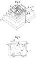
- FIG. 1 a hydraulic control system is shown and generally designated 10.
- Figure 1 shows that the system 10 includes a solenoid assembly module 12 and a hydraulic interface plate 14 that are bolted or otherwise affixed to a transmission mounting plate 16 that extends from a vehicle transmission 18. It can be appreciated that the solenoid assembly module 12 and hydraulic interface plate 14 can be attached to any other hydraulic device that requires an array of solenoid valves to control the flow of fluid thereto.
- Figure 1 shows that the solenoid assembly module 12 includes plural solenoid valves 20 that are attached to a solenoid mounting plate 22.
- the solenoid mounting plate 22 is formed with plural threaded solenoid mounting plate fastener holes 24 and a threaded fastener 26, e.g., a bolt, threadably engages each threaded solenoid mounting plate faster hole 24.
- a molded lead frame 28 is mounted above and electrically connected to the solenoid valves 20.
- the hydraulic interface plate 14 defines a thickness 30.
- the solenoid mounting plate 22 defines a lower surface 32 ( Figure 2).
- the interface plate 14 defines an upper surface 34 ( Figure 3) and a lower surface 36 ( Figure 4).
- the transmission mounting plate 16 defines an upper surface 38 ( Figure 5). It is to be understood that when the system 10 is assembled, the lower surface 32 of the solenoid mounting plate 22 mates with the upper surface 34 of the interface plate 14 and the lower surface 36 of the interface plate 14 mates with the upper surface 38 of the mounting plate 16.
- Figure 2 shows that the solenoid mounting plate 22 is formed with plural solenoid fluid ports 40 that are in fluid communication with the solenoid valves 20.
- the solenoid fluid ports 40 are bored perpendicular to the bottom surface 32 of the solenoid mounting plate 22.
- the solenoid mounting plate 22 has an overall width 42 and an overall length 44. These dimensions are approximately equal to the below described dimensions of the interface plate 14 and the transmission mounting plate 16.
- the interface plate 14 is also formed with plural interface plate fastener holes 46.
- the interface plate fastener holes 46 are formed in the interface plate 14 so that they can be aligned with the threaded solenoid mounting plate fastener holes 24 during assembly. It is to be understood that the threaded fasteners 26 are inserted through the interface plate fastener holes 46 when threadably engaged with the threaded solenoid mounting plate fastener holes 24.
- the hydraulic interface plate 14 includes plural upper fluid routing channels 48 that are milled or otherwise formed laterally in the upper surface 34 of the interface plate 14. It can be appreciated that the upper fluid routing channels 48 can have different shapes and sizes, as shown in Figure 3. As further shown, the hydraulic interface plate 14 includes plural interface fluid ports 50. Preferably, each interface fluid port 50 is bored perpendicularly to the upper surface 34 of the hydraulic interface plate 14 and is located within a respective fluid routing channel 48. Figure 3 also shows that the hydraulic interface plate 14 defines an overall width 52 and an overall length 54. These dimensions are approximately equal to the width 42 and length 44 of the solenoid mounting plate 22.
- the shape of the perimeter of the hydraulic interface plate 14 is the same as the shape of the perimeter of the solenoid mounting plate 22.
- the interface plate 14 can have a different outer perimeter geometry than the solenoid mounting plate 22.
- Figure 4 shows that the hydraulic interface plate 14 further includes plural lower fluid routing channels 56 that are milled or otherwise formed laterally in the lower surface 36 of the hydraulic interface plate.
- the lower fluid routing channels 56 can have different shapes and sizes and are configured to mate with transmission fluid channels 58 ( Figure 5) formed in the transmission mounting plate 16.
- Figure 4 shows that the interface fluid ports 50, described above, lead from the upper fluid routing channels 48 to the lower fluid routing channels 56. It can be appreciated that the thickness 30 ( Figure 1) of the hydraulic interface plate 14 is dependant on the depth of the fluid routing channels 48, 56.
- Figure 5 shows that the transmission mounting plate 16 has an overall width 60 and overall length 62 that are approximately equal to the widths 42, 52 and lengths 44, 54 of the solenoid mounting plate 22 and the hydraulic interface plate 14. Also, the transmission mounting plate 16 is formed with plural transmission mounting plate fastener holes 64 through which the threaded fasteners 26 are also inserted when properly engaged with the threaded solenoid mounting plate fastener holes 24. It can be appreciated that the solenoid mounting plate fastener holes 24 can be smooth-bored while the transmission mounting plate fastener holes 64 can be threaded. Thus, the threaded fasteners 26 can be inserted through the solenoid mounting plate 22 and the interface plate 14 in order to attached the plates 22, 24 to the transmission mounting plate 16.
- the interface plate 14 is in fluid communication with the solenoid valves 20 mounted on the solenoid mounting plate 22 and the transmission 18. It is to be understood that the interface plate 14 transmits fluid from the individual solenoid valves 20 to the transmission through the upper fluid routing channels 48, the interface ports 50, and the lower fluid routing channels 56.
- the positioning of the solenoid valves 20 on the solenoid mounting plate 22 and other components can be based more on the optimal usage of the available space and less on the channels 56 formed in the transmission plate 16.
- the solenoid assembly module 12 can be standardized while the hydraulic interface plate 14, specifically the location, the size, and the shape of the upper and lower fluid routing channels 48, 56 and the interface ports 50, can be varied to match transmission mounting plates 16 of varying configurations.
Landscapes
- Engineering & Computer Science (AREA)
- General Engineering & Computer Science (AREA)
- Mechanical Engineering (AREA)
- Physics & Mathematics (AREA)
- Fluid Mechanics (AREA)
- Control Of Transmission Device (AREA)
- General Details Of Gearings (AREA)
Applications Claiming Priority (2)
| Application Number | Priority Date | Filing Date | Title |
|---|---|---|---|
| US10/238,477 US20040045614A1 (en) | 2002-09-10 | 2002-09-10 | Hydraulic interface plate |
| US238477 | 2002-09-10 |
Publications (2)
| Publication Number | Publication Date |
|---|---|
| EP1398513A2 true EP1398513A2 (de) | 2004-03-17 |
| EP1398513A3 EP1398513A3 (de) | 2005-06-08 |
Family
ID=31887733
Family Applications (1)
| Application Number | Title | Priority Date | Filing Date |
|---|---|---|---|
| EP20030077482 Withdrawn EP1398513A3 (de) | 2002-09-10 | 2003-08-08 | Hydraulische Zwischenscheibe |
Country Status (2)
| Country | Link |
|---|---|
| US (1) | US20040045614A1 (de) |
| EP (1) | EP1398513A3 (de) |
Cited By (2)
| Publication number | Priority date | Publication date | Assignee | Title |
|---|---|---|---|---|
| US10221721B2 (en) | 2015-06-19 | 2019-03-05 | Hamilton Sundstrand Corporation | Hydraulic line routing plate |
| US11584223B2 (en) | 2020-06-23 | 2023-02-21 | Deere & Company | Transmission subassembly, clutch module and vehicle |
Families Citing this family (5)
| Publication number | Priority date | Publication date | Assignee | Title |
|---|---|---|---|---|
| JP3846437B2 (ja) * | 2003-03-17 | 2006-11-15 | 株式会社日立製作所 | 自動車用コントロールユニット |
| JP5365552B2 (ja) * | 2010-03-09 | 2013-12-11 | マツダ株式会社 | 自動変速機の制御装置 |
| US9488268B2 (en) * | 2013-05-30 | 2016-11-08 | Keihin Corporation | Hydraulic pressure control apparatus |
| DE102019125893A1 (de) * | 2019-09-26 | 2021-04-01 | Wabco Europe Bvba | Getriebesteuereinheit |
| US11624450B2 (en) * | 2021-04-29 | 2023-04-11 | Applied Materials, Inc. | Fluid delivery mounting panel and system |
Family Cites Families (10)
| Publication number | Priority date | Publication date | Assignee | Title |
|---|---|---|---|---|
| DE1917727C3 (de) * | 1969-04-05 | 1974-08-01 | Samson Apparatebau Ag, 6000 Frankfurt | Leitungssystem für hydraulisch oder pneumatisch arbeitende Schalt-, Steuer- oder Regeleinrichtungen |
| US4449426A (en) * | 1977-08-15 | 1984-05-22 | Younger Gilbert W | Laminated separator plate means for recalibrating automatic transmissions |
| GB2074251A (en) * | 1980-04-18 | 1981-10-28 | Dowty Mining Equipment Ltd | Fluid-pressure apparatus |
| JP2923839B2 (ja) * | 1994-09-20 | 1999-07-26 | 本田技研工業株式会社 | 油圧制御装置 |
| US6186486B1 (en) * | 1999-07-30 | 2001-02-13 | Delphi Technologies, Inc. | Jounce bumper plate |
| US6485005B1 (en) * | 2000-11-03 | 2002-11-26 | Delphi Technologies, Inc. | Hydraulic mount with gas spring supported decoupler |
| US6547226B2 (en) * | 2001-02-05 | 2003-04-15 | Delphi Technologies, Inc. | Bi-state hydraulic mount with annular decoupler |
| US6422545B1 (en) * | 2001-02-09 | 2002-07-23 | Delphi Technologies, Inc. | Vacuum actuated active decoupler mount |
| US6439556B1 (en) * | 2001-02-15 | 2002-08-27 | Delphi Technologies, Inc. | Active decoupler hydraulic mount |
| US6412761B1 (en) * | 2001-04-25 | 2002-07-02 | Delphi Technologies, Inc. | Hybrid hydraulic mount with magnetorheological fluid chamber |
-
2002
- 2002-09-10 US US10/238,477 patent/US20040045614A1/en not_active Abandoned
-
2003
- 2003-08-08 EP EP20030077482 patent/EP1398513A3/de not_active Withdrawn
Cited By (3)
| Publication number | Priority date | Publication date | Assignee | Title |
|---|---|---|---|---|
| US10221721B2 (en) | 2015-06-19 | 2019-03-05 | Hamilton Sundstrand Corporation | Hydraulic line routing plate |
| US10502097B2 (en) | 2015-06-19 | 2019-12-10 | Hamilton Sundstrand Corporation | Hydraulic line routing plate |
| US11584223B2 (en) | 2020-06-23 | 2023-02-21 | Deere & Company | Transmission subassembly, clutch module and vehicle |
Also Published As
| Publication number | Publication date |
|---|---|
| US20040045614A1 (en) | 2004-03-11 |
| EP1398513A3 (de) | 2005-06-08 |
Similar Documents
| Publication | Publication Date | Title |
|---|---|---|
| EP1260743B1 (de) | Fluidregelvorrichtung | |
| US7152629B2 (en) | Fluid control device | |
| US6929031B2 (en) | Electro-hydraulic manifold assembly with lead frame mounted pressure sensors | |
| US5855229A (en) | Solenoid manifold assembly | |
| EP0816731A2 (de) | Ventilverteiler | |
| JPH06323456A (ja) | マニホールドバルブ | |
| EP1398513A2 (de) | Hydraulische Zwischenscheibe | |
| CN222458803U (zh) | 流体分配系统和用于车辆可重构热管理的流体分配系统 | |
| EP0758069A1 (de) | Stützklemme für eine Rohrkuppung eines Umschaltventils | |
| US20040177950A1 (en) | Stacked plate heat exchanger with integrated connector | |
| US8042573B2 (en) | Fluid control device | |
| JP2004197947A (ja) | 電気流体圧式マニホールド組立体およびその圧力トランスデューサの取付け方法 | |
| EP1008764A1 (de) | Anschlussblock für mehrere Ventile | |
| EP1284380A2 (de) | Verfahren und Vorrichtung zum Montieren von Elektromagnetventilen | |
| US4301832A (en) | Pressure converter valve | |
| US7486996B2 (en) | Transmission control unit having pressure transducer package | |
| CN100396893C (zh) | 用于滤油器适配器的法兰盘 | |
| US6205886B1 (en) | Control valve devices for automatic transmissions | |
| JP2008215400A (ja) | 電磁弁マニホールド | |
| US20060108095A1 (en) | Connector for a plate heat exchanger | |
| CN212177831U (zh) | 一种防呆式汽车变速箱锁止杠杆 | |
| JPH0320161A (ja) | 自動変速機のコントロールバルブユニット | |
| JP2518205Y2 (ja) | 電磁弁装置 | |
| EP1890075A1 (de) | Verbindungsvorrichtung für einen durchgangsblock | |
| WO2018132093A1 (en) | Solenoid body with integrated lead frame |
Legal Events
| Date | Code | Title | Description |
|---|---|---|---|
| PUAI | Public reference made under article 153(3) epc to a published international application that has entered the european phase |
Free format text: ORIGINAL CODE: 0009012 |
|
| AK | Designated contracting states |
Kind code of ref document: A2 Designated state(s): AT BE BG CH CY CZ DE DK EE ES FI FR GB GR HU IE IT LI LU MC NL PT RO SE SI SK TR |
|
| AX | Request for extension of the european patent |
Extension state: AL LT LV MK |
|
| PUAL | Search report despatched |
Free format text: ORIGINAL CODE: 0009013 |
|
| AK | Designated contracting states |
Kind code of ref document: A3 Designated state(s): AT BE BG CH CY CZ DE DK EE ES FI FR GB GR HU IE IT LI LU MC NL PT RO SE SI SK TR |
|
| AX | Request for extension of the european patent |
Extension state: AL LT LV MK |
|
| AKX | Designation fees paid | ||
| REG | Reference to a national code |
Ref country code: DE Ref legal event code: 8566 |
|
| STAA | Information on the status of an ep patent application or granted ep patent |
Free format text: STATUS: THE APPLICATION IS DEEMED TO BE WITHDRAWN |
|
| 18D | Application deemed to be withdrawn |
Effective date: 20051209 |