EP1398500A2 - Vertical axis wind turbine with wind collector - Google Patents
Vertical axis wind turbine with wind collector Download PDFInfo
- Publication number
- EP1398500A2 EP1398500A2 EP20030020747 EP03020747A EP1398500A2 EP 1398500 A2 EP1398500 A2 EP 1398500A2 EP 20030020747 EP20030020747 EP 20030020747 EP 03020747 A EP03020747 A EP 03020747A EP 1398500 A2 EP1398500 A2 EP 1398500A2
- Authority
- EP
- European Patent Office
- Prior art keywords
- casing structure
- rotor
- machine
- side passages
- vertical axis
- Prior art date
- Legal status (The legal status is an assumption and is not a legal conclusion. Google has not performed a legal analysis and makes no representation as to the accuracy of the status listed.)
- Withdrawn
Links
- 238000011144 upstream manufacturing Methods 0.000 claims description 5
- 239000002245 particle Substances 0.000 description 9
- 238000000605 extraction Methods 0.000 description 6
- 230000008901 benefit Effects 0.000 description 3
- 241001465754 Metazoa Species 0.000 description 1
- 230000004075 alteration Effects 0.000 description 1
- 230000003796 beauty Effects 0.000 description 1
- 238000010276 construction Methods 0.000 description 1
- 239000000284 extract Substances 0.000 description 1
- 238000009434 installation Methods 0.000 description 1
- 238000000034 method Methods 0.000 description 1
Images


Classifications
-
- F—MECHANICAL ENGINEERING; LIGHTING; HEATING; WEAPONS; BLASTING
- F03—MACHINES OR ENGINES FOR LIQUIDS; WIND, SPRING, OR WEIGHT MOTORS; PRODUCING MECHANICAL POWER OR A REACTIVE PROPULSIVE THRUST, NOT OTHERWISE PROVIDED FOR
- F03D—WIND MOTORS
- F03D3/00—Wind motors with rotation axis substantially perpendicular to the air flow entering the rotor
- F03D3/04—Wind motors with rotation axis substantially perpendicular to the air flow entering the rotor having stationary wind-guiding means, e.g. with shrouds or channels
- F03D3/0427—Wind motors with rotation axis substantially perpendicular to the air flow entering the rotor having stationary wind-guiding means, e.g. with shrouds or channels with converging inlets, i.e. the guiding means intercepting an area greater than the effective rotor area
-
- Y—GENERAL TAGGING OF NEW TECHNOLOGICAL DEVELOPMENTS; GENERAL TAGGING OF CROSS-SECTIONAL TECHNOLOGIES SPANNING OVER SEVERAL SECTIONS OF THE IPC; TECHNICAL SUBJECTS COVERED BY FORMER USPC CROSS-REFERENCE ART COLLECTIONS [XRACs] AND DIGESTS
- Y02—TECHNOLOGIES OR APPLICATIONS FOR MITIGATION OR ADAPTATION AGAINST CLIMATE CHANGE
- Y02E—REDUCTION OF GREENHOUSE GAS [GHG] EMISSIONS, RELATED TO ENERGY GENERATION, TRANSMISSION OR DISTRIBUTION
- Y02E10/00—Energy generation through renewable energy sources
- Y02E10/70—Wind energy
- Y02E10/74—Wind turbines with rotation axis perpendicular to the wind direction
Definitions
- This invention relates to a machine for generating energy from a wind source. More particularly, this invention relates to a machine having a rotor that is caused to rotate around a vertical axis by a wind source.
- the rotor may be coupled to a dynamo-electric generator in order to produce electric power for downstream consumption.
- machines for generating energy from wind sources can include large wind turbines mounted at wind sites, along with various deflectors placed upstream of the turbine. Such arrangements can be difficult to install at the wind sites, as the placement of the various deflectors can be complex. In addition, such an arrangement can be unaesthetic and can lessen the beauty of the landscape at the wind site.
- a machine for generating energy from a wind source having a casing structure within which a rotor having a vertical axis of rotation is positioned.
- the solutions of the present invention simplify the construction process of the machinery and its installation at a wind site. Furthermore, the machinery may be adjusted to optimize the power extraction from a wind source, and achieves a minimal ecological impact when installed at the wind site.
- the machinery is applicable for a wide range of power rating consumptions (e.g., from ratings of domestic applications to ratings of primary wind power stations).
- the machine for generating usable energy from a wind source has a casing structure.
- a rotor having a blade structure is positioned within the casing structure and has a substantially vertical axis of rotation.
- the casing structure may define an air inlet upstream of the rotor that is oriented with respect to a prevailing wind direction and an air outlet downstream of the rotor.
- the casing structure may have a main passage through which air flows and interacts with the blade structure.
- the casing structure may have first and second side passages that are delimited by first and second sidewalls of the casing structure, respectively. The first and second side passages may converge toward one another near the air outlet forming a zone of low pressure downstream of the rotor.
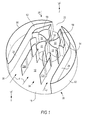
- FIG. 1 is a partial perspective view of the energy generating machine of the present invention, with certain parts removed to show other parts that would otherwise be hidden.
- FIG. 2 is a view as seen from direction 2--2 of FIG. 1.
- FIG. 3 is an enlargement of portion 3 of FIG. 2.
- FIG. 4 is a sectional view as seen from direction 4--4 of FIG. 2, and which also shows the parts which have been removed in FIG. 1.
- rotor 10 is located in passage 12 for rotation around vertical axis 14 in direction 15 when driven by a wind source (e.g., a natural wind source).
- a wind source e.g., a natural wind source.
- Vertical axis 14 is substantially perpendicular to upper cover plate 16 and lower cover plate 18 of general casing structure 20.
- Upper cover plate 16 and lower cover plate 18 may be substantially horizontal, and therefore parallel to a ground plane that supports general casing structure 20. (In FIG. 1, upper cover plate 16 is not shown in order to show other parts of the machine that would otherwise be hidden.)
- Rotor 10 may include a blade structure.
- the blade structure of rotor 10 includes a plurality of blades 22 that are cantilevered from rotation shaft 24.
- Blades 22 may be panels having a concave configuration, as shown in the FIGS.
- Blades 22 may have other configurations, such as a spiral shape, to increase the power extraction from the wind source.
- Passage 12 may be delimited laterally by opposite side walls 26 and 28 and vertically by upper and lower cover plates 16 and 18, respectively.
- Side walls 26 and 28 extend from inlet opening 30 of passage 12 to outlet opening 32 of passage 12. Side walls 26 and 28 may be substantially parallel to each other in portion 34 of passage 12, while sidewalls 26 and 28 may converge towards each other in portion 36 of passage 12. Inlet opening 30 faces a prevailing wind direction in order to collect and achieve air flow F in portion 34 of passage 12.
- Air flow deflector members consisting of upstanding panels 38-43, are spaced apart at predetermined positions in portion 34 in order to partially surround rotor 10 along a circular sector 46. Portions F i of air flow F are deflected by panels 38-43, thereby causing the air particles of flow F to fill compartments 48 of the rotor. Compartments 48 are delimited by blades 22 and upper and lower cover plates 16 and 18, respectively.
- the configurations of panels 38-43 (shown as both concave and straight in the FIGS.), and their orientation, cause the air particles to impinge on the surfaces of blades 22 at predetermined angles.
- the predetermined angles influence the resultant driving force achieved on rotor 10 by the wind source.
- the air particles that enter compartments 48 rotate with rotor 10 and run along blades 22 until they are discharged through passage 50. Thus, the air particles lose their quantity of motion or energy in order to drive rotor 10.
- Narrow passages 52 and 54 which are respectively delimited by sidewalls 26 and 28, are on opposite sides of the circular sector 46 occupied by panels 38-43.
- Upstanding casing structures 56 and 58 are located in another circular sector 60 surrounding rotor 10. Face 62 of casing structure 56, together with panel 38, form passage 64. Similarly, face 66 of casing structure 58, together with panel 43, form passage 68. Face 70 of casing structure 56 surrounds a portion of rotor 10. Similarly, face 72 of casing structure 58 surrounds another portion of rotor 10. Passage 50 is formed between face 74 and face 76. Face 78 and sidewall 26 complete narrow passage 52. Similarly, face 80 and sidewall 28 complete narrow passage 54. Preferably, passage 50 is centered on axis 82, and narrow passages 52 and 54 are spaced symmetrically apart with respect to axis 82, as shown in the FIGS.
- portions of air flow F that have not entered rotor 10 will run through narrow passages 52 and 54 to create a low pressure region in portion 36.
- the low pressure region in portion 36 induces the extraction of air particles from rotor 10 through passage 50.
- the extraction occurs when a compartment 48 of rotor 10 is facing passage 50.
- the sectional size of passage 50 influences the average speed of the air particles when moving with rotor 10. More particularly, a restricted sectional size of passage 50, compared to the total sectional size of passages formed by panels 38-43 on sector 46, increases the average speed of the air particles rotating with rotor 10. The increase in the average speed of the air particles extracts more rotation power for rotor 10, which consequently increases the electric power that can be obtained for downstream consumption.
- the low pressure region 36 extends beyond outlet opening 32 so that the air particles of flow F are ultimately discharged from passage 32.
- Rotor 10 is supported for rotation in direction 15 by supporting shaft 24 in bearings 84 and 86, seated in upper cover plate 16 and lower cover plate 18, respectively (see FIG. 4).
- Dynamo-electric generator 88 may be coupled to shaft 24, as shown in FIG. 4.
- Lower case plate 18 may be provided with wheels 94, which may be supported and guided by ground rail 96.
- Ground rail 96 may be circular in order to rotate lower case plate 18 around a vertical axis of the machinery.
- Circular rack 98 which lines lower cover plate 18 and is concentric to the vertical axis of the machinery, may be engaged by pinion 100 of motor 102.
- motor 102 By rotation of motor 102, general casing structure 20 may be rotated around the vertical axis of the machinery to orient inlet opening 30 with respect to a prevailing wind direction, thereby maximizing power extraction from the wind source.
- the prevailing wind direction may be sensed by a wind direction sensor that supplies information signals which may be used by a control and regulation unit to drive motor 102, resulting in calculated rotations that orient inlet opening 30 with respect to the prevailing wind direction.
- the external cylindrical form of general casing structure 20 offers low air obstruction when rotating general casing structure 20 around the vertical axis of the machinery to orient inlet opening 30 with respect to the prevailing wind direction.
- baffles 104 may be rotated towards each other to form a diverging passage for the air flow reaching and passing through rotor 10.
- a rotated position of baffles 104 is shown by the dashed lines in FIG. 2.
- rotor 10 within general casing structure 20 greatly reduces the noise level that rotor 10 produces during rotation caused by the wind source.
- protection grids may be installed across inlet opening 30 and outlet opening 32 to prevent humans and animals from entering passage 12. The protection grids would be visible and would present low air obstructions to the air flow F needed in passage 12.
- Higher power ratings of the machinery may be achieved by increasing the overall sizes of rotor 10 and passage 12.
- the major increases in size can be in the diameter of rotor 10 and in the plan dimensions of passage 12. These alterations would result in a lower height of general casing structure 20 with respect to the height of traditional wind driven machinery having the same power rating.
- An increase of the power ratings can also be achieved by mounting multiple units, such as the unit shown in FIG. 4, one above the other in order to form a vertical column of small plan occupancy.
- the machine of the present invention may be installed in various locations where it is desired to produce electric power from a wind source.
- the machine of the present invention may be installed on a roof of a tall building in an urban setting, thereby taking advantage of the high winds present at such a height and making efficient use of available space.
Landscapes
- Engineering & Computer Science (AREA)
- Life Sciences & Earth Sciences (AREA)
- Sustainable Development (AREA)
- Sustainable Energy (AREA)
- Chemical & Material Sciences (AREA)
- Combustion & Propulsion (AREA)
- Mechanical Engineering (AREA)
- General Engineering & Computer Science (AREA)
- Wind Motors (AREA)
Abstract
A machine for generating usable energy from a
wind source is provided. The machine includes a casing
structure that may define an air inlet oriented with
respect to a prevailing wind direction and an air
outlet. The casing structure may be substantially
cylindrical. A rotor having a blade structure is
positioned within the casing structure and has a
substantially vertical axis of rotation. The casing
structure may include two side passages for creating a
zone of low pressure downstream of the rotor near the
air outlet.
Description
- This application claims the benefit of United States provisional patent application No. 60/410,782, filed September 13, 2002.
- This invention relates to a machine for generating energy from a wind source. More particularly, this invention relates to a machine having a rotor that is caused to rotate around a vertical axis by a wind source. The rotor may be coupled to a dynamo-electric generator in order to produce electric power for downstream consumption.
- Currently, machines for generating energy from wind sources can include large wind turbines mounted at wind sites, along with various deflectors placed upstream of the turbine. Such arrangements can be difficult to install at the wind sites, as the placement of the various deflectors can be complex. In addition, such an arrangement can be unaesthetic and can lessen the beauty of the landscape at the wind site.
- Accordingly, it would be desirable to provide a machine for generating energy from a wind source having a casing structure within which a rotor having a vertical axis of rotation is positioned.
- In accordance with the present invention, a machine for generating energy from a wind source is provided having a casing structure within which a rotor having a vertical axis of rotation is positioned.
- The solutions of the present invention simplify the construction process of the machinery and its installation at a wind site. Furthermore, the machinery may be adjusted to optimize the power extraction from a wind source, and achieves a minimal ecological impact when installed at the wind site. The machinery is applicable for a wide range of power rating consumptions (e.g., from ratings of domestic applications to ratings of primary wind power stations).
- In some embodiments of the present invention, the machine for generating usable energy from a wind source has a casing structure. A rotor having a blade structure is positioned within the casing structure and has a substantially vertical axis of rotation. The casing structure may define an air inlet upstream of the rotor that is oriented with respect to a prevailing wind direction and an air outlet downstream of the rotor. The casing structure may have a main passage through which air flows and interacts with the blade structure. The casing structure may have first and second side passages that are delimited by first and second sidewalls of the casing structure, respectively. The first and second side passages may converge toward one another near the air outlet forming a zone of low pressure downstream of the rotor.
- Further features of the invention, its nature and various advantages will be more apparent from the accompanying drawings and the following detailed description.
- FIG. 1 is a partial perspective view of the energy generating machine of the present invention, with certain parts removed to show other parts that would otherwise be hidden.
- FIG. 2 is a view as seen from
direction 2--2 of FIG. 1. - FIG. 3 is an enlargement of portion 3 of FIG. 2.
- FIG. 4 is a sectional view as seen from
direction 4--4 of FIG. 2, and which also shows the parts which have been removed in FIG. 1. - As shown in FIGS. 1-3,
rotor 10 is located inpassage 12 for rotation aroundvertical axis 14 in direction 15 when driven by a wind source (e.g., a natural wind source).Vertical axis 14 is substantially perpendicular toupper cover plate 16 andlower cover plate 18 ofgeneral casing structure 20.Upper cover plate 16 andlower cover plate 18 may be substantially horizontal, and therefore parallel to a ground plane that supportsgeneral casing structure 20. (In FIG. 1,upper cover plate 16 is not shown in order to show other parts of the machine that would otherwise be hidden.) -
Rotor 10 may include a blade structure. In the example shown in the FIGS., the blade structure ofrotor 10 includes a plurality ofblades 22 that are cantilevered fromrotation shaft 24.Blades 22 may be panels having a concave configuration, as shown in the FIGS.Blades 22 may have other configurations, such as a spiral shape, to increase the power extraction from the wind source.Passage 12 may be delimited laterally byopposite side walls lower cover plates -
Side walls passage 12 to outlet opening 32 ofpassage 12.Side walls portion 34 ofpassage 12, whilesidewalls portion 36 ofpassage 12. Inlet opening 30 faces a prevailing wind direction in order to collect and achieve air flow F inportion 34 ofpassage 12. - In
portion 34, the path of air flow F is initially parallel tosidewalls portion 34 in order to partially surroundrotor 10 along acircular sector 46. Portions Fi of air flow F are deflected by panels 38-43, thereby causing the air particles of flow F to fillcompartments 48 of the rotor.Compartments 48 are delimited byblades 22 and upper andlower cover plates blades 22 at predetermined angles. The predetermined angles influence the resultant driving force achieved onrotor 10 by the wind source. The air particles that entercompartments 48 rotate withrotor 10 and run alongblades 22 until they are discharged throughpassage 50. Thus, the air particles lose their quantity of motion or energy in order to driverotor 10. -
Narrow passages sidewalls circular sector 46 occupied by panels 38-43. Upper andlower cover plates passages - Upstanding
casing structures circular sector 60 surroundingrotor 10.Face 62 ofcasing structure 56, together withpanel 38,form passage 64. Similarly,face 66 ofcasing structure 58, together with panel 43,form passage 68.Face 70 ofcasing structure 56 surrounds a portion ofrotor 10. Similarly,face 72 ofcasing structure 58 surrounds another portion ofrotor 10. Passage 50 is formed betweenface 74 andface 76.Face 78 andsidewall 26 completenarrow passage 52. Similarly,face 80 andsidewall 28 completenarrow passage 54. Preferably,passage 50 is centered onaxis 82, andnarrow passages axis 82, as shown in the FIGS. - By means of the described arrangement, portions of air flow F that have not entered rotor 10 (see portions of air flow F referenced as F1 and F2) will run through
narrow passages portion 36. The low pressure region inportion 36 induces the extraction of air particles fromrotor 10 throughpassage 50. The extraction occurs when acompartment 48 ofrotor 10 is facingpassage 50. The sectional size ofpassage 50 influences the average speed of the air particles when moving withrotor 10. More particularly, a restricted sectional size ofpassage 50, compared to the total sectional size of passages formed by panels 38-43 onsector 46, increases the average speed of the air particles rotating withrotor 10. The increase in the average speed of the air particles extracts more rotation power forrotor 10, which consequently increases the electric power that can be obtained for downstream consumption. - The
low pressure region 36 extends beyond outlet opening 32 so that the air particles of flow F are ultimately discharged frompassage 32. -
Rotor 10 is supported for rotation in direction 15 by supportingshaft 24 inbearings upper cover plate 16 andlower cover plate 18, respectively (see FIG. 4). Dynamo-electric generator 88 may be coupled toshaft 24, as shown in FIG. 4. -
External plates side walls general casing structure 20 has a homogenous cylindrical appearance to the external observer. In addition, the resulting cylindrical form ofgeneral casing structure 20 presents low disruption to air flow investing the entirety ofgeneral casing structure 20. -
Lower case plate 18 may be provided withwheels 94, which may be supported and guided byground rail 96.Ground rail 96 may be circular in order to rotatelower case plate 18 around a vertical axis of the machinery.Circular rack 98, which lineslower cover plate 18 and is concentric to the vertical axis of the machinery, may be engaged bypinion 100 ofmotor 102. By rotation ofmotor 102,general casing structure 20 may be rotated around the vertical axis of the machinery to orient inlet opening 30 with respect to a prevailing wind direction, thereby maximizing power extraction from the wind source. - The prevailing wind direction may be sensed by a wind direction sensor that supplies information signals which may be used by a control and regulation unit to drive
motor 102, resulting in calculated rotations that orient inlet opening 30 with respect to the prevailing wind direction. The external cylindrical form ofgeneral casing structure 20 offers low air obstruction when rotatinggeneral casing structure 20 around the vertical axis of the machinery to orient inlet opening 30 with respect to the prevailing wind direction. - Limiting the power extraction from the wind source in situations of high wind speeds may be achieved by rotating
baffles 104 towards each other to form a diverging passage for the air flow reaching and passing throughrotor 10. A rotated position ofbaffles 104 is shown by the dashed lines in FIG. 2. - The inclusion of
rotor 10 withingeneral casing structure 20 greatly reduces the noise level thatrotor 10 produces during rotation caused by the wind source. Furthermore, protection grids (not shown) may be installed across inlet opening 30 and outlet opening 32 to prevent humans and animals from enteringpassage 12. The protection grids would be visible and would present low air obstructions to the air flow F needed inpassage 12. - Higher power ratings of the machinery may be achieved by increasing the overall sizes of
rotor 10 andpassage 12. The major increases in size can be in the diameter ofrotor 10 and in the plan dimensions ofpassage 12. These alterations would result in a lower height ofgeneral casing structure 20 with respect to the height of traditional wind driven machinery having the same power rating. An increase of the power ratings can also be achieved by mounting multiple units, such as the unit shown in FIG. 4, one above the other in order to form a vertical column of small plan occupancy. - The machine of the present invention may be installed in various locations where it is desired to produce electric power from a wind source. For example, the machine of the present invention may be installed on a roof of a tall building in an urban setting, thereby taking advantage of the high winds present at such a height and making efficient use of available space.
- Thus, a wind powered energy generating machine is provided. One skilled in the art will realize that the present invention can be practiced by other than the described embodiments, which are presented for purposes of illustration and not of limitation, and that the present invention is limited only by the claims which follow.
Claims (13)
- A machine for generating usable energy from a wind source, comprising:wherein the rotor is positioned within the casing structure, and wherein the rotor has a substantially vertical axis of rotation.a casing structure; anda rotor having a blade structure,
- The machine of claim 1, wherein the casing structure defines an air inlet upstream of the rotor that is oriented with respect to a prevailing wind direction and an air outlet downstream of the rotor.
- The machine of claim 1 or 2, wherein the casing structure has a main passage, and wherein air flows through the main passage and interacts with the blade structure.
- The machine of claim 1, 2, or 3, wherein the casing structure has first and second side passages, wherein the first and second side passages are delimited by first and second sidewalls of the casing structure, respectively, and wherein the first and second side passages converge toward one another near the air outlet forming a zone of low pressure downstream of the rotor.
- The machine of claim 1, wherein the casing structure has an outer surface that is substantially cylindrical.
- The machine of claim 1, wherein the blade structure comprises a plurality of blades spaced circumferentially apart around the axis of rotation of the rotor.
- The machine of claim 3, wherein the casing structure has first and second side passages, wherein the first and second side passages are delimited by first and second sidewalls of the casing structure, respectively, and wherein the first and second side passages converge toward one another near the air outlet forming a zone of low pressure downstream of the rotor, the machine further comprising:lower and upper cover plates, wherein the lower and upper cover plates vertically delimit the main passage and the first and second side passages.
- The machine of claim 3, wherein the casing structure has first and second side passages, wherein the first and second side passages are delimited by first and second sidewalls of the casing structure, respectively, and wherein the first and second side passages converge toward one another near the air outlet forming a zone of low pressure downstream of the rotor, the machine further comprising:lower and upper cover plates, wherein the lower and upper cover plates are substantially perpendicular to the axis of rotation of the rotor, and wherein the lower and upper cover plates vertically delimit the main passage and the first and second side passages.
- The machine of claim 1, further comprising:a plurality of baffles, wherein the plurality of baffles are mounted within the casing structure upstream of the rotor, and wherein each baffle of the plurality of baffles has a substantially vertical axis of rotation.
- The machine of claim 1, further comprising:a plurality of panels, wherein the plurality of panels are mounted within the casing structure upstream of the rotor, and wherein the plurality of panels are spaced apart from one another and partially surround a portion of the rotor.
- The machine of claim 4, further comprising:first and second side passage structures, wherein the first and second side passage structures partially surround a portion of the rotor, and wherein the first and second side passages are further delimited by the first and second side passage structures, respectively.
- The machine of claim 2, further comprising:means for rotating the casing structure about a vertical axis of the casing structure to orient the air inlet with respect to the prevailing wind direction.
- The machine of claim 2, further comprising:means for rotating the casing structure about a vertical axis of the casing structure to orient the air inlet with respect to the prevailing wind direction, the means for rotating comprising:a ground rail; anda plurality of wheels, wherein the wheels are mounted on the casing structure and engage the ground rail to rotate the casing structure about the vertical axis of the casing structure.
Applications Claiming Priority (4)
| Application Number | Priority Date | Filing Date | Title |
|---|---|---|---|
| US661762 | 1991-02-27 | ||
| US41078202P | 2002-09-13 | 2002-09-13 | |
| US410782P | 2002-09-13 | ||
| US10/661,762 US6849964B2 (en) | 2002-09-13 | 2003-09-11 | Wind powered energy generating machine |
Publications (1)
| Publication Number | Publication Date |
|---|---|
| EP1398500A2 true EP1398500A2 (en) | 2004-03-17 |
Family
ID=31891548
Family Applications (1)
| Application Number | Title | Priority Date | Filing Date |
|---|---|---|---|
| EP20030020747 Withdrawn EP1398500A2 (en) | 2002-09-13 | 2003-09-12 | Vertical axis wind turbine with wind collector |
Country Status (3)
| Country | Link |
|---|---|
| US (1) | US6849964B2 (en) |
| EP (1) | EP1398500A2 (en) |
| CA (1) | CA2440655A1 (en) |
Cited By (13)
| Publication number | Priority date | Publication date | Assignee | Title |
|---|---|---|---|---|
| DE102005041600B3 (en) * | 2005-09-01 | 2006-12-14 | Josef Schmidt | Wind-driven power plant has vertical rotor axis carrying cam-shaped rotor within annular chamber defining channel having wind inlet and outlet |
| KR100889043B1 (en) | 2007-01-30 | 2009-03-20 | 아이알윈드파워 주식회사 | Wind power system which has a air-compressor and a air-inducer turned according to the direction of the wind |
| DE202008015173U1 (en) | 2008-11-15 | 2009-06-25 | Peickert, Ulrich Joachim Christian, Dipl.-Arch. | Axial symmetric wind turbine with vertical axes and photovoltaic |
| KR101040435B1 (en) | 2008-09-19 | 2011-06-09 | 김영수 | Wind Power Generation Apparatus using Movement Means |
| LT5751B (en) | 2009-10-30 | 2011-08-25 | Dainius MAČYS Dainius MAČYS | Vertical axis wind turbine |
| US8013464B2 (en) | 2005-07-28 | 2011-09-06 | Cleanfield Energy Corp. | Power generating system including modular wind turbine-generator assembly |
| EP2379881A1 (en) * | 2008-12-24 | 2011-10-26 | Dominick Daniel Martino | Prime mover |
| DE102011014476A1 (en) * | 2011-01-14 | 2012-07-19 | Thomas R. Class | Wind turbine for driving power generator in wind power plant, has wind guiding plate guiding wind and impinging at more than specified degree of rotor-circumference on rotor and over circumferential angle of specified degrees to rotor |
| DE102012011743A1 (en) * | 2012-06-10 | 2013-12-12 | Josef Gentischer | Wind turbine has turbine blades that are provided at inlet of turbine drum, and located at specific angle |
| EP2703639A4 (en) * | 2011-04-28 | 2015-06-03 | Myung-Soon Bae | Multipurpose rotary device, and generating system including same |
| LT6212B (en) | 2013-12-06 | 2015-08-25 | Vlado Bložės Pį | The vertical axis tornado wind turbine |
| WO2016116901A1 (en) * | 2015-01-22 | 2016-07-28 | Waldemar Piskorz | Wind turbine with rotational air guides |
| US9702340B2 (en) | 2008-12-24 | 2017-07-11 | Dominick Daniel Martino | Prime mover |
Families Citing this family (36)
| Publication number | Priority date | Publication date | Assignee | Title |
|---|---|---|---|---|
| CA2452965A1 (en) * | 2003-12-31 | 2005-06-30 | Bud T. J. Johnson | Wind powered turbine engine-horizontal rotor configuration |
| CA2452967A1 (en) * | 2003-12-31 | 2005-06-30 | Bud T. J. Johnson | Wind powered turbine engine-speedball configuration |
| CA2467199A1 (en) * | 2004-05-19 | 2005-11-19 | Bud T.J. Johnson | Wind turbine |
| US20070009347A1 (en) * | 2005-07-06 | 2007-01-11 | Henri Duong | Generate electricity by concentrating wind, by moving transportation, by flowing of liquid, by sun burning, etc in utility of housing, industry, etc |
| US7354247B2 (en) | 2005-10-27 | 2008-04-08 | General Electric Company | Blade for a rotor of a wind energy turbine |
| US7880323B2 (en) * | 2006-06-10 | 2011-02-01 | Menges Pamela A | Wind generator system |
| US11644010B1 (en) | 2006-06-10 | 2023-05-09 | Star Sailor Energy, Inc. | Energy storage system |
| US8648481B2 (en) * | 2006-06-10 | 2014-02-11 | Star Sailor Energy, Inc. | Wind generator with energy enhancer element for providing energy at no wind and low wind conditions |
| US7365448B2 (en) * | 2006-08-17 | 2008-04-29 | X Blade Systems Lp | Wind driven power generator |
| US7911076B2 (en) * | 2006-08-17 | 2011-03-22 | Broadstar Developments, Lp | Wind driven power generator with moveable cam |
| US8262338B2 (en) * | 2007-01-11 | 2012-09-11 | Cassidy Joe C | Vertical axis dual vortex downwind inward flow impulse wind turbine |
| US7521816B2 (en) * | 2007-03-01 | 2009-04-21 | Helfrich Jim C | Water current powered motor |
| US8164210B2 (en) * | 2007-03-07 | 2012-04-24 | Boone Daniel N | Vertical axis wind turbine with angled braces |
| US7453168B2 (en) * | 2007-04-02 | 2008-11-18 | Lanie Robert C | Wind-powered generator system for generating electric power over a wide range of wind conditions |
| US8072091B2 (en) * | 2007-04-18 | 2011-12-06 | Samuel B. Wilson, III | Methods, systems, and devices for energy generation |
| US20080303286A1 (en) * | 2007-06-06 | 2008-12-11 | Vangel Peter D | Wind electrical generation system |
| CN101566124B (en) * | 2008-04-21 | 2011-10-05 | 钟俊能 | Power generation device capable of collecting wind in many directions |
| US7605491B1 (en) * | 2008-05-22 | 2009-10-20 | Chun-Neng Chung | Apparatus for generating electric power using wind energy |
| GB0913877D0 (en) * | 2009-08-10 | 2009-09-16 | Cross Flow Energy Company Ltd | A device for translating fluid flow into rotary motion |
| US20110037261A1 (en) * | 2009-08-11 | 2011-02-17 | KTCR Holding, Inc. | System And Method For Producing Electrical Power |
| WO2011057067A1 (en) | 2009-11-05 | 2011-05-12 | Cliff Bassett | Systems and methods to generate electricity using a flow of air |
| WO2013096649A1 (en) * | 2011-12-20 | 2013-06-27 | Bassett Clifford | Wind lens assembly |
| US8591170B1 (en) | 2010-05-26 | 2013-11-26 | James D. Rawls | Directed force turbine device |
| US20120175882A1 (en) * | 2011-01-10 | 2012-07-12 | Peter John Sterling | Injector venturi accelerated, wind turbine |
| US9611832B2 (en) * | 2011-03-30 | 2017-04-04 | Shandong Boxing Yuandao Energy Technology Co., Ltd. | Water flow power generation apparatus |
| CA2770782C (en) * | 2011-05-18 | 2013-07-09 | Yuji Unno | Hydraulic power generating apparatus |
| SK6617Y1 (en) * | 2013-01-17 | 2013-12-02 | martin Ottmar | Wind turbine |
| CN107250531A (en) * | 2014-08-12 | 2017-10-13 | 蒋素芳 | A kind of wind power generation plant and system |
| US9631603B2 (en) * | 2014-08-20 | 2017-04-25 | Don Allen Harwood | Wing with slipstream turbine |
| US9371818B1 (en) | 2015-08-10 | 2016-06-21 | Mark T. Monto | Cyclonic aeolian vortex turbine |
| AR103820A1 (en) * | 2016-03-01 | 2017-06-07 | Klarenberg Alejandro José | CONSTRUCTION DEFINING A SUBMERGED VOLUME IN AN AIR CURRENT, ABLE TO ADDRESS AND ACCELERATE THIS AIR CURRENT TO AT LEAST A WIND GENERATOR ASSOCIATED WITH SUCH CONSTRUCTION |
| US11578606B2 (en) * | 2017-11-22 | 2023-02-14 | Cesar Mercier | Fluid displacement turbine |
| US11085415B1 (en) | 2017-12-22 | 2021-08-10 | Star Sailor Energy, Inc. | Wind generator system having a biomimetic aerodynamic element for use in improving the efficiency of the system |
| CA3034183C (en) * | 2018-02-22 | 2021-03-16 | Ralph Dominic Raina | Single or bi-directional, scalable turbine |
| US11519384B2 (en) | 2018-08-01 | 2022-12-06 | Mark Monto | Venturi vortex and flow facilitating turbine |
| CN109798216A (en) * | 2018-09-26 | 2019-05-24 | 上海理工大学 | A kind of perpendicular axis type hydraulic turbine with separate type speedup conflux plate |
Family Cites Families (4)
| Publication number | Priority date | Publication date | Assignee | Title |
|---|---|---|---|---|
| US5375968A (en) | 1993-06-02 | 1994-12-27 | Kollitz; Gerhard | Wind turbine generator |
| US5852331A (en) * | 1996-06-21 | 1998-12-22 | Giorgini; Roberto | Wind turbine booster |
| US6177735B1 (en) * | 1996-10-30 | 2001-01-23 | Jamie C. Chapman | Integrated rotor-generator |
| US6465899B2 (en) * | 2001-02-12 | 2002-10-15 | Gary D. Roberts | Omni-directional vertical-axis wind turbine |
-
2003
- 2003-09-11 US US10/661,762 patent/US6849964B2/en not_active Expired - Fee Related
- 2003-09-12 CA CA002440655A patent/CA2440655A1/en not_active Abandoned
- 2003-09-12 EP EP20030020747 patent/EP1398500A2/en not_active Withdrawn
Cited By (16)
| Publication number | Priority date | Publication date | Assignee | Title |
|---|---|---|---|---|
| US8013464B2 (en) | 2005-07-28 | 2011-09-06 | Cleanfield Energy Corp. | Power generating system including modular wind turbine-generator assembly |
| DE102005041600B3 (en) * | 2005-09-01 | 2006-12-14 | Josef Schmidt | Wind-driven power plant has vertical rotor axis carrying cam-shaped rotor within annular chamber defining channel having wind inlet and outlet |
| KR100889043B1 (en) | 2007-01-30 | 2009-03-20 | 아이알윈드파워 주식회사 | Wind power system which has a air-compressor and a air-inducer turned according to the direction of the wind |
| KR101040435B1 (en) | 2008-09-19 | 2011-06-09 | 김영수 | Wind Power Generation Apparatus using Movement Means |
| DE202008015173U1 (en) | 2008-11-15 | 2009-06-25 | Peickert, Ulrich Joachim Christian, Dipl.-Arch. | Axial symmetric wind turbine with vertical axes and photovoltaic |
| EP2379881A4 (en) * | 2008-12-24 | 2014-04-02 | Dominick Daniel Martino | Prime mover |
| EP2379881A1 (en) * | 2008-12-24 | 2011-10-26 | Dominick Daniel Martino | Prime mover |
| US9702340B2 (en) | 2008-12-24 | 2017-07-11 | Dominick Daniel Martino | Prime mover |
| LT5751B (en) | 2009-10-30 | 2011-08-25 | Dainius MAČYS Dainius MAČYS | Vertical axis wind turbine |
| DE102011014476B4 (en) * | 2011-01-14 | 2016-03-10 | Thomas R. Class | wind turbine |
| DE102011014476A1 (en) * | 2011-01-14 | 2012-07-19 | Thomas R. Class | Wind turbine for driving power generator in wind power plant, has wind guiding plate guiding wind and impinging at more than specified degree of rotor-circumference on rotor and over circumferential angle of specified degrees to rotor |
| EP2703639A4 (en) * | 2011-04-28 | 2015-06-03 | Myung-Soon Bae | Multipurpose rotary device, and generating system including same |
| US9512815B2 (en) | 2011-04-28 | 2016-12-06 | Myung-soon Bae | Multipurpose rotary device and generating system including same |
| DE102012011743A1 (en) * | 2012-06-10 | 2013-12-12 | Josef Gentischer | Wind turbine has turbine blades that are provided at inlet of turbine drum, and located at specific angle |
| LT6212B (en) | 2013-12-06 | 2015-08-25 | Vlado Bložės Pį | The vertical axis tornado wind turbine |
| WO2016116901A1 (en) * | 2015-01-22 | 2016-07-28 | Waldemar Piskorz | Wind turbine with rotational air guides |
Also Published As
| Publication number | Publication date |
|---|---|
| CA2440655A1 (en) | 2004-03-13 |
| US20040100103A1 (en) | 2004-05-27 |
| US6849964B2 (en) | 2005-02-01 |
Similar Documents
| Publication | Publication Date | Title |
|---|---|---|
| US6849964B2 (en) | Wind powered energy generating machine | |
| US8961103B1 (en) | Vertical axis wind turbine with axial flow rotor | |
| US9284943B2 (en) | Vertical axis wind turbine | |
| US6808366B2 (en) | Fluid flow powered dynamo with lobed rotors | |
| US9567971B2 (en) | Conical fan assembly for use in a wind turbine for the generation of power | |
| US8791588B2 (en) | Low-profile power-generating wind turbine | |
| JP2002339853A (en) | Charge station | |
| KR101299915B1 (en) | Apparatus for generating by wind power | |
| AU2010359619B2 (en) | Vertical axis turbine | |
| US9567972B2 (en) | Nozzle assembly for use with a wind lens system for the generation of electric power | |
| WO2016023351A1 (en) | All-directional flow-guide shaftless wind-driven generator | |
| US8754541B2 (en) | Linear wind powered electrical generator | |
| WO2021140243A1 (en) | Systems and methods for harnessing energy from wind | |
| KR101924375B1 (en) | Vertical Wind Turbine | |
| US9145868B2 (en) | Vertical axis turbine and constructions employing same | |
| WO2011161821A1 (en) | Wind collection apparatus and windmill apparatus | |
| KR101019907B1 (en) | Wind turbine | |
| JP3162839U (en) | Wind power generators applied to automobiles | |
| KR20120068136A (en) | Wind generator | |
| CN114370371A (en) | Wind-gathering efficient vertical axis wind power generation device | |
| CN105221338A (en) | Wind-power generating system | |
| KR20130033010A (en) | Wind power system | |
| KR20090004412A (en) | Wind generator | |
| KR101746446B1 (en) | Wind power generator with wind increasing chamber | |
| KR102694132B1 (en) | Wind power generation apparatus |
Legal Events
| Date | Code | Title | Description |
|---|---|---|---|
| PUAI | Public reference made under article 153(3) epc to a published international application that has entered the european phase |
Free format text: ORIGINAL CODE: 0009012 |
|
| AK | Designated contracting states |
Kind code of ref document: A2 Designated state(s): AT BE BG CH CY CZ DE DK EE ES FI FR GB GR HU IE IT LI LU MC NL PT RO SE SI SK TR |
|
| AX | Request for extension of the european patent |
Extension state: AL LT LV MK |
|
| STAA | Information on the status of an ep patent application or granted ep patent |
Free format text: STATUS: THE APPLICATION IS DEEMED TO BE WITHDRAWN |
|
| 18D | Application deemed to be withdrawn |
Effective date: 20061031 |