EP1398226A1 - Inflation assembly for variable profile air bag - Google Patents
Inflation assembly for variable profile air bag Download PDFInfo
- Publication number
- EP1398226A1 EP1398226A1 EP20030077632 EP03077632A EP1398226A1 EP 1398226 A1 EP1398226 A1 EP 1398226A1 EP 20030077632 EP20030077632 EP 20030077632 EP 03077632 A EP03077632 A EP 03077632A EP 1398226 A1 EP1398226 A1 EP 1398226A1
- Authority
- EP
- European Patent Office
- Prior art keywords
- initiator
- air bag
- gas
- activation
- inflation gas
- Prior art date
- Legal status (The legal status is an assumption and is not a legal conclusion. Google has not performed a legal analysis and makes no representation as to the accuracy of the status listed.)
- Granted
Links
Images


Classifications
-
- B—PERFORMING OPERATIONS; TRANSPORTING
- B60—VEHICLES IN GENERAL
- B60R—VEHICLES, VEHICLE FITTINGS, OR VEHICLE PARTS, NOT OTHERWISE PROVIDED FOR
- B60R21/00—Arrangements or fittings on vehicles for protecting or preventing injuries to occupants or pedestrians in case of accidents or other traffic risks
- B60R21/02—Occupant safety arrangements or fittings, e.g. crash pads
- B60R21/16—Inflatable occupant restraints or confinements designed to inflate upon impact or impending impact, e.g. air bags
- B60R21/23—Inflatable members
- B60R21/231—Inflatable members characterised by their shape, construction or spatial configuration
- B60R21/233—Inflatable members characterised by their shape, construction or spatial configuration comprising a plurality of individual compartments; comprising two or more bag-like members, one within the other
-
- B—PERFORMING OPERATIONS; TRANSPORTING
- B60—VEHICLES IN GENERAL
- B60R—VEHICLES, VEHICLE FITTINGS, OR VEHICLE PARTS, NOT OTHERWISE PROVIDED FOR
- B60R21/00—Arrangements or fittings on vehicles for protecting or preventing injuries to occupants or pedestrians in case of accidents or other traffic risks
- B60R21/02—Occupant safety arrangements or fittings, e.g. crash pads
- B60R21/16—Inflatable occupant restraints or confinements designed to inflate upon impact or impending impact, e.g. air bags
- B60R21/26—Inflatable occupant restraints or confinements designed to inflate upon impact or impending impact, e.g. air bags characterised by the inflation fluid source or means to control inflation fluid flow
- B60R21/268—Inflatable occupant restraints or confinements designed to inflate upon impact or impending impact, e.g. air bags characterised by the inflation fluid source or means to control inflation fluid flow using instantaneous release of stored pressurised gas
- B60R21/272—Inflatable occupant restraints or confinements designed to inflate upon impact or impending impact, e.g. air bags characterised by the inflation fluid source or means to control inflation fluid flow using instantaneous release of stored pressurised gas with means for increasing the pressure of the gas just before or during liberation, e.g. hybrid inflators
-
- B—PERFORMING OPERATIONS; TRANSPORTING
- B60—VEHICLES IN GENERAL
- B60R—VEHICLES, VEHICLE FITTINGS, OR VEHICLE PARTS, NOT OTHERWISE PROVIDED FOR
- B60R21/00—Arrangements or fittings on vehicles for protecting or preventing injuries to occupants or pedestrians in case of accidents or other traffic risks
- B60R21/02—Occupant safety arrangements or fittings, e.g. crash pads
- B60R21/16—Inflatable occupant restraints or confinements designed to inflate upon impact or impending impact, e.g. air bags
- B60R21/23—Inflatable members
- B60R21/231—Inflatable members characterised by their shape, construction or spatial configuration
- B60R21/2334—Expansion control features
- B60R21/2338—Tethers
-
- B—PERFORMING OPERATIONS; TRANSPORTING
- B60—VEHICLES IN GENERAL
- B60R—VEHICLES, VEHICLE FITTINGS, OR VEHICLE PARTS, NOT OTHERWISE PROVIDED FOR
- B60R21/00—Arrangements or fittings on vehicles for protecting or preventing injuries to occupants or pedestrians in case of accidents or other traffic risks
- B60R21/02—Occupant safety arrangements or fittings, e.g. crash pads
- B60R21/16—Inflatable occupant restraints or confinements designed to inflate upon impact or impending impact, e.g. air bags
- B60R21/26—Inflatable occupant restraints or confinements designed to inflate upon impact or impending impact, e.g. air bags characterised by the inflation fluid source or means to control inflation fluid flow
- B60R21/263—Inflatable occupant restraints or confinements designed to inflate upon impact or impending impact, e.g. air bags characterised by the inflation fluid source or means to control inflation fluid flow using a variable source, e.g. plural stage or controlled output
-
- B—PERFORMING OPERATIONS; TRANSPORTING
- B60—VEHICLES IN GENERAL
- B60R—VEHICLES, VEHICLE FITTINGS, OR VEHICLE PARTS, NOT OTHERWISE PROVIDED FOR
- B60R21/00—Arrangements or fittings on vehicles for protecting or preventing injuries to occupants or pedestrians in case of accidents or other traffic risks
- B60R21/02—Occupant safety arrangements or fittings, e.g. crash pads
- B60R21/16—Inflatable occupant restraints or confinements designed to inflate upon impact or impending impact, e.g. air bags
- B60R21/23—Inflatable members
- B60R21/231—Inflatable members characterised by their shape, construction or spatial configuration
- B60R21/2334—Expansion control features
- B60R21/2338—Tethers
- B60R2021/23382—Internal tether means
-
- B—PERFORMING OPERATIONS; TRANSPORTING
- B60—VEHICLES IN GENERAL
- B60R—VEHICLES, VEHICLE FITTINGS, OR VEHICLE PARTS, NOT OTHERWISE PROVIDED FOR
- B60R21/00—Arrangements or fittings on vehicles for protecting or preventing injuries to occupants or pedestrians in case of accidents or other traffic risks
- B60R21/02—Occupant safety arrangements or fittings, e.g. crash pads
- B60R21/16—Inflatable occupant restraints or confinements designed to inflate upon impact or impending impact, e.g. air bags
- B60R21/26—Inflatable occupant restraints or confinements designed to inflate upon impact or impending impact, e.g. air bags characterised by the inflation fluid source or means to control inflation fluid flow
- B60R2021/26058—Inflatable occupant restraints or confinements designed to inflate upon impact or impending impact, e.g. air bags characterised by the inflation fluid source or means to control inflation fluid flow using a combination of inflators
-
- B—PERFORMING OPERATIONS; TRANSPORTING
- B60—VEHICLES IN GENERAL
- B60R—VEHICLES, VEHICLE FITTINGS, OR VEHICLE PARTS, NOT OTHERWISE PROVIDED FOR
- B60R21/00—Arrangements or fittings on vehicles for protecting or preventing injuries to occupants or pedestrians in case of accidents or other traffic risks
- B60R21/02—Occupant safety arrangements or fittings, e.g. crash pads
- B60R21/16—Inflatable occupant restraints or confinements designed to inflate upon impact or impending impact, e.g. air bags
- B60R21/26—Inflatable occupant restraints or confinements designed to inflate upon impact or impending impact, e.g. air bags characterised by the inflation fluid source or means to control inflation fluid flow
- B60R2021/26094—Inflatable occupant restraints or confinements designed to inflate upon impact or impending impact, e.g. air bags characterised by the inflation fluid source or means to control inflation fluid flow characterised by fluid flow controlling valves
-
- B—PERFORMING OPERATIONS; TRANSPORTING
- B60—VEHICLES IN GENERAL
- B60R—VEHICLES, VEHICLE FITTINGS, OR VEHICLE PARTS, NOT OTHERWISE PROVIDED FOR
- B60R21/00—Arrangements or fittings on vehicles for protecting or preventing injuries to occupants or pedestrians in case of accidents or other traffic risks
- B60R21/02—Occupant safety arrangements or fittings, e.g. crash pads
- B60R21/16—Inflatable occupant restraints or confinements designed to inflate upon impact or impending impact, e.g. air bags
- B60R21/26—Inflatable occupant restraints or confinements designed to inflate upon impact or impending impact, e.g. air bags characterised by the inflation fluid source or means to control inflation fluid flow
- B60R21/263—Inflatable occupant restraints or confinements designed to inflate upon impact or impending impact, e.g. air bags characterised by the inflation fluid source or means to control inflation fluid flow using a variable source, e.g. plural stage or controlled output
- B60R2021/2633—Inflatable occupant restraints or confinements designed to inflate upon impact or impending impact, e.g. air bags characterised by the inflation fluid source or means to control inflation fluid flow using a variable source, e.g. plural stage or controlled output with a plurality of inflation levels
-
- B—PERFORMING OPERATIONS; TRANSPORTING
- B60—VEHICLES IN GENERAL
- B60R—VEHICLES, VEHICLE FITTINGS, OR VEHICLE PARTS, NOT OTHERWISE PROVIDED FOR
- B60R21/00—Arrangements or fittings on vehicles for protecting or preventing injuries to occupants or pedestrians in case of accidents or other traffic risks
- B60R21/02—Occupant safety arrangements or fittings, e.g. crash pads
- B60R21/16—Inflatable occupant restraints or confinements designed to inflate upon impact or impending impact, e.g. air bags
- B60R21/26—Inflatable occupant restraints or confinements designed to inflate upon impact or impending impact, e.g. air bags characterised by the inflation fluid source or means to control inflation fluid flow
- B60R21/264—Inflatable occupant restraints or confinements designed to inflate upon impact or impending impact, e.g. air bags characterised by the inflation fluid source or means to control inflation fluid flow using instantaneous generation of gas, e.g. pyrotechnic
- B60R21/2644—Inflatable occupant restraints or confinements designed to inflate upon impact or impending impact, e.g. air bags characterised by the inflation fluid source or means to control inflation fluid flow using instantaneous generation of gas, e.g. pyrotechnic using only solid reacting substances, e.g. pellets, powder
- B60R2021/2648—Inflatable occupant restraints or confinements designed to inflate upon impact or impending impact, e.g. air bags characterised by the inflation fluid source or means to control inflation fluid flow using instantaneous generation of gas, e.g. pyrotechnic using only solid reacting substances, e.g. pellets, powder comprising a plurality of combustion chambers or sub-chambers
-
- B—PERFORMING OPERATIONS; TRANSPORTING
- B60—VEHICLES IN GENERAL
- B60R—VEHICLES, VEHICLE FITTINGS, OR VEHICLE PARTS, NOT OTHERWISE PROVIDED FOR
- B60R21/00—Arrangements or fittings on vehicles for protecting or preventing injuries to occupants or pedestrians in case of accidents or other traffic risks
- B60R21/02—Occupant safety arrangements or fittings, e.g. crash pads
- B60R21/16—Inflatable occupant restraints or confinements designed to inflate upon impact or impending impact, e.g. air bags
- B60R21/26—Inflatable occupant restraints or confinements designed to inflate upon impact or impending impact, e.g. air bags characterised by the inflation fluid source or means to control inflation fluid flow
- B60R21/268—Inflatable occupant restraints or confinements designed to inflate upon impact or impending impact, e.g. air bags characterised by the inflation fluid source or means to control inflation fluid flow using instantaneous release of stored pressurised gas
- B60R2021/2685—Inflatable occupant restraints or confinements designed to inflate upon impact or impending impact, e.g. air bags characterised by the inflation fluid source or means to control inflation fluid flow using instantaneous release of stored pressurised gas comprising a plurality of pressure chambers
-
- B—PERFORMING OPERATIONS; TRANSPORTING
- B60—VEHICLES IN GENERAL
- B60R—VEHICLES, VEHICLE FITTINGS, OR VEHICLE PARTS, NOT OTHERWISE PROVIDED FOR
- B60R21/00—Arrangements or fittings on vehicles for protecting or preventing injuries to occupants or pedestrians in case of accidents or other traffic risks
- B60R21/02—Occupant safety arrangements or fittings, e.g. crash pads
- B60R21/16—Inflatable occupant restraints or confinements designed to inflate upon impact or impending impact, e.g. air bags
- B60R21/20—Arrangements for storing inflatable members in their non-use or deflated condition; Arrangement or mounting of air bag modules or components
- B60R21/217—Inflation fluid source retainers, e.g. reaction canisters; Connection of bags, covers, diffusers or inflation fluid sources therewith or together
- B60R21/2171—Inflation fluid source retainers, e.g. reaction canisters; Connection of bags, covers, diffusers or inflation fluid sources therewith or together specially adapted for elongated cylindrical or bottle-like inflators with a symmetry axis perpendicular to the main direction of bag deployment, e.g. extruded reaction canisters
-
- B—PERFORMING OPERATIONS; TRANSPORTING
- B60—VEHICLES IN GENERAL
- B60R—VEHICLES, VEHICLE FITTINGS, OR VEHICLE PARTS, NOT OTHERWISE PROVIDED FOR
- B60R21/00—Arrangements or fittings on vehicles for protecting or preventing injuries to occupants or pedestrians in case of accidents or other traffic risks
- B60R21/02—Occupant safety arrangements or fittings, e.g. crash pads
- B60R21/16—Inflatable occupant restraints or confinements designed to inflate upon impact or impending impact, e.g. air bags
- B60R21/23—Inflatable members
- B60R21/231—Inflatable members characterised by their shape, construction or spatial configuration
- B60R21/2334—Expansion control features
- B60R21/2342—Tear seams
-
- B—PERFORMING OPERATIONS; TRANSPORTING
- B60—VEHICLES IN GENERAL
- B60R—VEHICLES, VEHICLE FITTINGS, OR VEHICLE PARTS, NOT OTHERWISE PROVIDED FOR
- B60R21/00—Arrangements or fittings on vehicles for protecting or preventing injuries to occupants or pedestrians in case of accidents or other traffic risks
- B60R21/02—Occupant safety arrangements or fittings, e.g. crash pads
- B60R21/16—Inflatable occupant restraints or confinements designed to inflate upon impact or impending impact, e.g. air bags
- B60R21/26—Inflatable occupant restraints or confinements designed to inflate upon impact or impending impact, e.g. air bags characterised by the inflation fluid source or means to control inflation fluid flow
- B60R21/264—Inflatable occupant restraints or confinements designed to inflate upon impact or impending impact, e.g. air bags characterised by the inflation fluid source or means to control inflation fluid flow using instantaneous generation of gas, e.g. pyrotechnic
Landscapes
- Engineering & Computer Science (AREA)
- Mechanical Engineering (AREA)
- Physics & Mathematics (AREA)
- Fluid Mechanics (AREA)
- Air Bags (AREA)
Abstract
Description
- This invention relates generally to an air bag assembly, and more particularly to an air bag assembly capable of variable expansion by selective retention or release of restraining tether elements operatively connected to an inflatable cushion in combination with controlled conveyance of inflation gas to the inflatable cushion.
- It is well known to provide an air bag assembly including an inflatable air bag cushion for protecting the occupants of a transportation vehicle. In an automotive vehicle such air bag assemblies are typically located within the hub of the steering wheel and in a recess in the instrument panel for protection of the vehicle occupants seated in opposing relation to such assemblies. Additional air bag assemblies may be located within the seats and/or door panels for protection of the occupants during a side-impact event.
- Air bag assemblies typically include an inflatable cushion in fluid communication with a gas emitting inflator. Upon sensing certain predetermined vehicle conditions, such as a certain level of vehicle deceleration, the inflator discharges a fixed amount of inflator gas thereby forcing the air bag into a deployed position. The inflator gas occupies the available volume within the air bag cushion thereby forcing the air bag cushion to expand outwardly to the extent permitted by its construction.
As the occupant comes into contact with the expanded air bag, the inflator gas is forced out of the air bag thereby dissipating the kinetic energy of the occupant. - Absent restraint, an inflated body tends to assume a generally spherical profile. In order to provide control over the inflated shape of the air bag cushion, it is known to utilize tethering elements in the form of straps or webs extending between surfaces of the air bag cushion to thereby hold the surfaces in fixed orientation relative to one another upon inflation. The selection and length of such tethering elements can thus be used to establish a desired inflated profile. However, once the tethering elements are attached in fixed relation to the surface of the air bag cushion, the inflated geometry of the cushion is likewise fixed and is not subject to adjustment.
- It has been recognized that the preferred inflated profile of the air bag cushion may vary depending upon the severity of the activating impact event and/or upon the size and position of the occupant to be protected. Thus, the ability to effectively control the inflation characteristics of the air bag cushion is potentially desirable. In order to provide a degree of control over the inflated profile of the air bag cushion it is known to use an inflator that has varied levels or stages of inflator gas output in response to the sensing of different vehicle occupant conditions. Thus, it is generally known in the prior art to utilize so-called "dual-stage" inflators that discharge predetermined amounts of gas at one or two levels. However, the use of such "dual-stage" inflators provides control over only the amount of inflator gas which is discharged and does not provide control over the expanded geometry of the inflated air bag cushion. That is, due to the compressible nature of the inflation gas, so long as the air bag has a fixed volumetric capacity, the inflator gas will tend to fill that capacity and the expanded configuration of the air bag will be generally the same although the pressure may vary.
- In order to provide an additional level of control over the air bag performance it has been suggested to utilize air bag cushions which incorporate sewn or woven in seams within the air bag to control the expanded geometry of the inflated air bag. Such seams separate upon the introduction of pressures exceeding a certain level thereby freeing the air bag cushion from the restraint imposed by the seams at lower pressures. In order for such break-away seams to provide controlled expansion, the introduction of such seams must be carried out with substantial precision such that seam separation will occur in a highly reproducible and predictable manner. In some instances, such requisite precision and reproducibility may be difficult to achieve. Moreover, even when such break-away seams are utilized, the expansion which occurs may be in all directions. In some applications it is believed that preferential expansion in the depth of the air bag (i.e. towards the occupant to be protected) may be desirable.
- In order to address the desire to provide enhanced control over the final inflated profile of the air bag, it has been proposed to utilize release mechanisms to hold tether straps in place under normal conditions and to release the straps in situations where an extended profile is desired. By way of example only, and not limitation, various release mechanisms are illustrated and described in U. S. Patents 6,390,501 to Greib et al., 6,422,597 to Pinsenschaum et al. and 6,454,300 to Dunkle et al., the contents of all of which are incorporated by reference as if fully set forth herein.
- This invention provides advantages and alternatives over the prior art by providing a release mechanism of efficient construction and operation to hold restraining air bag tethers in place under a first set of predetermined conditions and to extend such tethers under a second set of predetermined conditions. The extension of the restraining tethers is carried out in conjunction with the delivery of an increased volume of inflating gas to the air bag cushion. The air bag assembly may be operated using as few as two activatable initiators to activate inflation stages within a dual stage inflator while simultaneously controlling tether length to effect delivery of a proper volume of inflation gas for a desired cushion profile.
- The present invention will now be described by way of example only, with reference to the accompanying drawings which constitute a part of the specification herein and in which:
- FIG. 1 is a cut-away view of a vehicle interior showing an air bag cushion in a stored undeployed state in opposing relation to a vehicle occupant;
- FIG. 2A is a view similar to FIG. 1 illustrating an air bag cushion in a deployed state restrained by an internal tether arrangement;
- FIG. 2B is a view similar to FIG. 2A wherein the tether arrangement is released to a second restrained state to permit enhanced expansion of the air bag cushion towards a vehicle occupant;
- FIG. 3 is a cut-away schematic side view of a dual stage inflator having two initiators and a selectively releasable tether restraint with a tether illustrated in a restrained operatively shortened condition;
- FIG. 4 is an end view of the inflator illustrated in FIG. 3 taken generally along line 4-4 in FIG. 3;
- FIG. 5 is a view similar to FIG. 3, with a first stage initiator in an activated condition so as to inflate an air bag cushion to a condition as illustrated in FIG. 2A;
- FIG. 6 is a view similar to FIG. 3, with a first stage initiator and a second stage initiator in an activated condition so as to release a restraining tether to a lengthened operative condition and inflate an air bag cushion to a condition as illustrated in FIG. 2B;
- FIG. 7 is a view similar to FIG. 5, including a puncture device in fluid communication with the second stage initiator;
- FIG. 8 is a view similar to FIG. 7, with the first stage initiator and second stage initiator activated and the puncture device pushed forward to open a conveyance path for gas from the second stage initiator;
- FIG. 9 is a view similar to FIG. 7, including an alternative arrangement for a puncture device in fluid communication with the second stage initiator; and
- FIG. 10 is a view similar to FIG. 9, with the first stage initiator and second stage initiator activated and the puncture device pushed forward to open a conveyance path for gas from the second stage initiator;
-
- While the invention has been illustrated and will hereinafter be described in connection with certain potentially preferred embodiments, procedures and practices, it is to be understood that in no event is the invention to be limited to such illustrated and described embodiments, procedures and practices. On the contrary, it is intended that the present invention shall extend to all alternatives and modifications as may embrace the principles of this invention within the true spirit and scope thereof.
- Reference will now be made to the drawings, wherein to the extent possible, like reference numerals are utilized to designate like components throughout the various views. In FIG. 1 a
vehicle 10 is shown including aseating structure 12 which supports anoccupant 14 in generally opposing relation to aninstrument panel 16. Anair bag assembly 18 including anair bag cushion 20 is housed within theinstrument panel 16 for outward deployment towards theoccupant 14 in the event of a collision. - While the
air bag assembly 18 and correspondingair bag cushion 20 are illustrated for descriptive purposes in relation to a vehicle passenger, it is to be understood that the present invention is in no way to be limited to a passenger side configuration. On the contrary, it is contemplated that the present invention may have applicability to air bag deployment in opposing relation to the operator (not shown) of thevehicle 10 as well as in relation to air bags deployed from other regions within the vehicle interior. - It is contemplated that the
vehicle 10 may include aseat position sensor 22 to detect the position of theoccupant 14 relative to theair bag assembly 18. It is further contemplated that thevehicle 10 may include additional position sensors such as anoptical scanner 24 or the like to measure both the volume and position of the occupant to be protected. Thevehicle 10 may also be provided with ascale 26 within theseating structure 12 so as to provide additional data regarding the load to which the inflatableair bag cushion 20 may be subjected upon impact by theoccupant 14. It is additionally contemplated that theseating structure 12 may be provided with sensing elements to measure the degree to which the seating structure is reclined. Thevehicle 10 may also be provided with sensors to determine and communicate whether or not the occupant is utilizing the recommendedseat belt structures 28. The data so collected may be combined at an on-board computer 19 which in turn, sends an activation signal to one or more initiators upon the occurrence of a collision event to release controlled volumes of inflation gas so as to effect the desirable expanded profile characteristics for theair bag cushion 20 in a given situation. - It is contemplated that the
air bag cushion 20 has a first restrained expanded profile which is obtained upon extension ofinternal tethering elements 30 held in a shortened operative length condition and at least a second restrained expanded profile which is characterized by greater depth than the first profile. As best illustrated through simultaneous reference to FIGS. 2A and 2B, it is contemplated that one ormore tethering elements 30 in the form of straps extending from locations at an interior or exterior surface of theair bag cushion 20 are utilized to control the inflated profile of theair bag cushion 20. Thetethering elements 30 are normally held to a shortened operative length between connection points 29 at the interior of the cushion and areleasable restraint assembly 36 in the vicinity of agas generating inflator 40. In this regard it is to be understood that the connection points 29 may be either fixed connection points or sliding connection points such as supporting sleeves or the like through which thetethering elements 30 are threaded. The releasable attachment at therestraint assembly 36 may be effected by use of an integral or supplemental slidingloop structure 25 such as a short length of cord or the like although it is contemplated that any number of other arrangements may likewise be utilized. - As shown in FIG. 2A under normal operating conditions, the
tethering elements 30 restrain the profile of the expandingair bag cushion 20 to a first diminished depth. By way of example only, and not limitation, it is contemplated that such a restrained profile may be of particular use in the protection of smaller stature occupants and/or occupants seated in close proximity to theinstrument panel 16. As shown in FIG. 2B, in instances where a deeper profile is desired, thetethering elements 30 may be released from therestraint assembly 36 thereby yielding a permissible expanded geometry of expanded depth. - It is contemplated that some degree of restraint may nonetheless be maintained by a length extending
tether extension 23 such as a strap or the like operatively connected between the tethering elements and asecondary attachment location 27 which may be either on the surface of the air bag cushion or at an external location. Thetethering elements 30 may be arranged within theair bag cushion 20 such that they are affixed at opposing ends to the surface of the cushion and are brought to a shortened operative condition by pulling an intermediate portion of the tethering elements through surface loops and towards therestraint assembly 36. Regardless of the tethering arrangement, it is contemplated that an expanded depth may be useful in the protection of larger stature occupants and/or in the protection of occupants seated a substantial distance away from theinstrument panel 16. - As will be appreciated, upon the release of the
tethering elements 30 from therestraint assembly 36, the volume of the air bag is increased. According to a potentially preferred practice, theair bag assembly 18 incorporates a selectively activatable variable inflation device which causes a controlled volume of inflation gas to be delivered to the air bag cushion depending upon the desired inflation characteristics. That is, the variable inflation device will deliver a greater volume of inflation gas to theair bag cushion 20 in instances where a deep profile such as is illustrated in FIG. 2B is desired. Conversely, in instances where a more shallow inflated profile is desired such as illustrated in FIG. 2A, a smaller volume of inflation gas is released into theair bag cushion 20. - According to a first exemplary practice, the variable inflation device incorporates a
displaceable plug element 42 which is operatively connected to a tether displacement orcarrier element 44 which makes up part of the releasable restraint assembly. In a potentially preferred arrangement, theplug element 42 is adapted to undergo a sliding displacement in conjunction with the delivery of an enhanced volume of inflation gas from theinflator 40. The sliding displacement of theplug element 42 is, in turn, translated to thetether displacement element 44 so as to carry thetethering elements 30 away from an anchoringstructure 46 thereby permitting thetethering elements 30 to be pulled away from an initial anchored position and assume an extended operative length. The sliding displacement of the plug element also opens up a normally closed auxiliary gas transfer path to convey an enhanced volume of inflation gas into the air bag cushion. - In the exemplary embodiment illustrated schematically in FIG. 3, the
inflator 40 includes aprimary diffuser 50 including an arrangement ofgas transmission openings 52 arranged so as to convey released inflation gas into an air bag cushion.
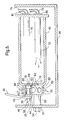
In the illustrated arrangement, astud 54 projecting away from aspacer 55 may be disposed at the surface of theprimary diffuser 50 for supporting attachment through a wall of aninflator housing 56 such as by anut 57 or other appropriate fastening device. Of course, virtually any other support arrangement as may be desired may likewise be utilized if desired. - As best illustrated through simultaneous reference to FIGS. 3 and 4, the anchoring
structure 46 may be made up of one or more support pins 58 which extend away from the outer face of the primary diffuser and in sliding relation through aligned openings in thetether displacement element 44. In the illustrated construction, the support pins 58 support thetethering elements 30 within the gap between walls of the slottedcarrier element 44. Thus, in the position illustrated in FIG. 3, thetethering element 30 is restrained on either side by the walls of thecarrier element 44 and thus cannot move away from the support pins 58. In the illustrated configuration, ascrew 60 or other attachment device extends through thecarrier element 44 and into theplug element 42 so as to establish an operative connection between thecarrier element 44 and theplug element 42. Of course, other means for effecting operative connection between thetether carrier element 44 and theplug element 42 such as welding, fusion bonding and adhesive connection may also be used if desired. - As illustrated, the
plug element 42 is housed within asecondary diffuser 62 including an arrangement ofgas transmission openings 63. As illustrated, in this arrangement the outer diameter of theplug element 42 is such that it slides within the secondary diffuser upon the application of a sufficient force in the direction of thecarrier element 44. While the actual configuration of theplug element 42 is not critical, it is contemplated that theplug element 42 may include a relatively large diametergas impingement portion 64 having an outer diameter which substantially fills the inner diameter of thesecondary diffuser 62. Thegas impingement portion 64 of theplug element 42 thus defines a reaction surface for contacting a pressurized stream of inflation gas to cause movement of the plug element along thesecondary diffuser 62 in a manner to be described further hereinafter.
Theplug element 42 may also have a reduceddiameter portion 65 projecting in the direction of movement of the plug element. - If desired, it is contemplated that
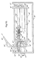
shear elements 66 may be disposed between theplug element 42 and thesecondary diffuser 63 to prevent undesired movement of theplug element 42 prior to the introduction of an activating driving force. Of course, such shear elements may be of any arrangement as may be desired. It is likewise contemplated that shear elements may be disposed at thecarrier element 44 rather than within thesecondary diffuser 62. - The operation of the device may be readily understood by reference to FIGS. 5 and 6. Referring first to FIG. 5, in the event that a reduced profile cushion deployment such as is illustrated in FIG. 2A is desired, an activating signal is sent by the on
board computer 19 to afirst initiator 69 such as a pyrotechnic squib or the like through leads 70. Theinitiator 69 activates aprimary gas generator 72 thereby causing a volume of inflation gas to be emitted from theprimary gas generator 72. Of course, it is to be understood that theprimary gas generator 72 may be of any suitable type as will be known to those of skill in the art. By way of example only, suitable gas generators may include chemical reactive inflators, stored gas inflators and hybrid inflators utilizing combinations of both chemical reaction and stored gas. - Upon emission of inflation gas from the
primary gas generator 72, a pressure will be developed within the body of the inflator 40 thereby causing the opening of a normally sealed first gas path opening 79 which is isolated from theimpingement portion 64 of theplug element 42. Inflation gas thus passes through the first gas path opening 79 into theprimary diffuser 50 and through thegas transmission openings 52 to an air bag cushion. Under the conditions illustrated in FIG. 5, asecond initiator 81 remains inactive and theplug element 42 andcarrier element 44 remain unmoved such that thetether element 30 remains secured at the support pins 58. - In the arrangement illustrated in FIG. 5 the selective expulsion of inflation gas into the
primary diffuser 50 without movement of theplug element 42 is effected by the use of afirst burst disk 77 disposed in covering relation to the first gas path opening 79. Asecond burst disk 78 is disposed in covering relation to a second gas path opening 80 which is in fluid communication with thegas impingement portion 64 of theplug element 42. As shown in FIG. 5, thefirst burst disk 77 is adapted to open upon exposure to pressure at a level developed within the inflator by activation of the primary gas generator. However, at this pressure the second burst disk remains intact thereby maintaining the isolation of the secondary discharge flow channel and thus avoiding pressurized displacement of theplug element 42. - As shown in FIG. 6, when an extended depth cushion profile such as illustrated in FIG. 2B is desired, activating signals are communicated through
leads first initiator 69 and to thesecond initiator 81 such as a pyrotechnic squib or the like. Under these conditions, theprimary gas generator 72 and thesecondary gas generator 75 are both activated so as to generate an enhanced volume of inflation gas. Due to this enhanced volume of inflation gas, an adequate pressure is developed to fracture thefirst burst disk 77 as well as thesecond burst disk 78. If desired, it is contemplated that the enhanced volume of inflation gas may be produced simply providing additional heat to the volume of gas expelled by a single gas generator. In such an arrangement the second gas generator may be eliminated if desired - As inflation gas passes under pressure through the second gas path opening 80, the inflation gas contacts the
gas impingement portion 64 of theplug element 42 with sufficient force to overcome theshear elements 66 and thereby push theplug element 42 along the length of thesecondary diffuser 62. As theplug element 42 is displaced,gas transmission openings 63 are opened thereby directing the driving gas outwardly and into the air bag cushion. As shown, the displacement of theplug element 42 is translated to the operatively connectedcarrier element 44 thereby causing thecarrier element 44 to push theloop structure 25 off of the support pins 58. Once the loop structure is clear of the support pins 58, thetether element 30 may be pulled away from thereleasable restraint assembly 36 by tension introduced by the inflating air bag cushion. As will be appreciated, this device can thus simultaneously adjust gas flow and tether length. Moreover, such adjustment may be carried out using only twoinitiators - Of course, it is to be understood that the present invention may be the subject of a wide range of alternatives. By way of example only, and not limitation, one alternative construction is illustrated in FIGS. 7 and 8 wherein elements corresponding to those previously described are designated by like reference numerals with a prime. As will be appreciated, the variable inflation device illustrated in FIGS. 7 and 8 operates in a substantially identical manner to the arrangement illustrated in FIGS. 5 and 6 with the exception that the second burst disk 78' is opened by a puncture element 85' which is pushed into contact with the second burst disk 78' upon activation of the secondary gas generator 75'.
- As illustrated, the puncture element 85' is normally held out of contact with the second burst disk 78' such as by a support member 86' spaced away from the second burst disk 78'. However, the puncture element is nonetheless disposed in fluid communication with the secondary gas generator 75' such as by a gas conduit 87'. Upon activation of the secondary gas generator 75', the puncture element 85' is driven forward so as to puncture the second burst disk and open up the second gas path opening 80' (FIG.8). Of course, various arrangements may be utilized to pass inflation gas from the secondary gas generator around and/or through the puncture element 85' after the puncture has taken place. By way of example only, it is contemplated that the puncture element 85' may include an arrangement of grooves 88' around its outer surface thereby allowing gas to pass around the puncture element. It is also contemplated that the puncture element 85' may include an arrangement of internal gas openings 89' through the interior. As will be appreciated, such external grooves and/or internal openings may be sized so as to allow passage of gas following puncture while nonetheless providing sufficient resistance to initiate displacement of the puncture element 85'. The support member 86' also preferably includes an arrangement of gas passages.
- Still another configuration is illustrated in FIGS. 9 and 10 in which elements corresponding to those previously described are designated by like reference numerals with a double prime. As will be appreciated, the configuration in FIGS. 9 and 10 is substantially the same as the construction illustrated in FIGS. 7 and 8 with the exception that second gas path opening 80" and covering
burst disk 78" are extended towards thesecondary gas generator 75" by anextension conduit 91". Such a construction may simplify construction and provide improved activation speed due to the shortened distance between thesecondary gas generator 75" and thepuncture element 85". - It is to be understood that while the present invention has been illustrated and described in relation to potentially preferred embodiments, constructions and procedures, that such embodiments, constructions and procedures are illustrative only and the present invention is in no event to be limited thereto. Rather it is contemplated that modifications and variations embodying the principles of the present invention will no doubt occur to those skilled in the art. It is therefore contemplated and intended that the present invention shall extend to all such modifications and variations as may incorporate the broad aspects of the present invention within the full spirit and scope thereof.
Claims (22)
- An air bag assembly (18) for cushioning restraint of an occupant (14) in a vehicle (10) during an impact event, the air bag assembly (18) comprising:a gas emitting inflator (40, 40', 40"), the inflator (40, 40', 40") including a first selectively activatable initiator (69, 69', 69") adapted to activate the release of a first volume of inflation gas and at least a second selectively activatable initiator (81, 81', 81"), the first initiator (69, 69', 69") being activateable either independently from the second initiator (81, 81', 81") or in conjunction with activation of the second initiator (81, 81', 81") such that upon activation of both the first initiator (69, 69', 69") and the second initiator (81, 81', 81") a second volume of inflation gas is released which is greater than the first volume of inflation gas;an inflatable air bag cushion (20) in fluid communication with the inflator (40, 40', 40") such that upon discharge of inflation gas from the inflator (40, 40', 40") the air bag cushion (20) is inflated to a deployed state;at least one profile restraining tethering element (30, 30', 30") operatively connected to the air bag cushion (20), the tethering element (30, 30', 30") further normally being operatively connected in releasable relation to a restraint assembly (46, 46', 46") remote from the air bag cushion (20) such that the profile restraining tethering element (30, 30', 30") is normally held in a shortened operative condition, wherein release of the tethering element (30, 30', 30") from the restraint assembly (46, 46', 46") is initiated by activation of the first initiator (69, 69', 69") in conjunction with activation of the second initiator (81, 81', 81") such that the profile restraining tether element (30, 30', 30") is released from operative connection to the restraint assembly (46, 46', 46") in conjunction with the emission of said second volume of inflation gas.
- The invention according to claim 1, wherein the first initiator (69, 69', 69") is a pyrotechnic squib.
- The invention according to claim 1, wherein both the first initiator (69, 69', 69") and the second initiator (81, 81', 81") are pyrotechnic squibs.
- The invention according to claim 1, wherein the inflator (40, 40', 40") includes a primary gas transfer path (79, 79', 79") adapted to transfer inflation gas into the air bag cushion (20) upon release of the first volume of inflation and a secondary gas transfer path (80, 80', 80") adapted to transfer inflation gas into the air bag cushion (20) upon release of the second volume of inflation gas and wherein the secondary gas transfer path (80, 80', 80") is isolated from inflation gas transmission prior to activation of the second initiator (81).
- The invention according to claim 4, wherein the secondary gas transfer path (80, 80', 80") is bounded by a diffuser (62, 62', 62") with a displaceable plug element (42, 42', 42") disposed within the diffuser (62, 62', 62"), the displaceable plug element (42, 42', 42") being adapted to move in response to gas pressure such that upon introduction of inflation gas into the secondary gas transfer path (80, 80', 80") the displaceable plug element (42, 42', 42") is moved at least partially along the diffuser (62, 62', 62").
- The invention according to claim 5, wherein the displaceable plug element (42, 42', 42") is adapted to at least partially block fluid transfer across the diffuser (62, 62', 62") and into the air bag cushion prior to movement of the displaceable plug element (42, 42', 42").
- The invention according to claim 6, wherein at least the secondary gas transfer path (80, 80', 80") is normally sealed from inflation gas by a sealing element (78, 78', 78") which is selectively opened upon activation of the second initiator (81, 81', 81").
- The invention according to claim 7, wherein the sealing element (78, 78', 78") comprises a rupture disk.
- The invention according to claim 8, wherein the rupture disk sealing the secondary gas transfer path (80, 80', 80") is adapted to spontaneously rupture upon application of a gas pressure generated by activation of the first initiator (69, 69', 69") in conjunction with activation of the second initiator (81, 81', 81").
- The invention according to claim 8, wherein the air bag assembly (18) includes a displaceable puncture element (85', 85") adapted to puncture the rupture disk upon activation of the second initiator (81', 81") such that the rupture disk is opened and inflation gas is conveyed into the secondary gas transfer path (80', 80").
- An air bag assembly (18) for cushioning restraint of an occupant (14) in a vehicle (10) during an impact event, the air bag assembly (18) comprising:a gas emitting inflator (40, 40', 40"), the inflator (40, 40', 40") including a first selectively activatable initiator (69, 69', 69") adapted to activate the release of a first volume of inflation gas and at least a second selectively activatable initiator (81, 81', 81"), the first initiator (69, 69', 69") being activatable either independently from the second initiator (81, 81', 81") or in conjunction with activation of the second initiator (81, 81', 81") such that upon activation of both the first initiator (69, 69', 69") and the second initiator (81, 81', 81") a second volume of inflation gas is released which is greater than the first volume of inflation gas;an inflatable air bag cushion (20) in fluid communication with the inflator (40, 40', 40") such that upon discharge of inflation gas from the inflator (40, 40', 40") the air bag cushion (20) is inflated to a deployed state;at least one profile restraining tethering element (30, 30', 30") operatively connected to the air bag cushion(20), the tethering element (30, 30', 30") further normally being operatively connected in releasable relation to a restraint assembly (46, 46', 46") remote from the air bag cushion (20) such that the profile restraining tethering element (30, 30', 30") is normally held in a shortened operative condition, the restraint assembly (46, 46', 46") including at least one support member (58, 58', 58") normally disposed in operative supporting relation to the profile restraining tethering element (30, 30', 30") and a displaceable carrier element (44, 44', 44") adapted to carry the profile restraining tethering element (30, 30', 30") away from supported relation at the support member (58, 58', 58") upon activation of both the first initiator (69, 69', 69") and the second initiator (81, 81', 81"), such that the profile restraining tethering element (30, 30', 30") is released from operative connection to the restraint assembly (46, 46', 46") in conjunction with the emission of said second volume of inflation gas.
- The invention according to claim 11, wherein the first initiator (69, 69', 69") is a pyrotechnic squib .
- The invention according to claim 11, wherein both the first initiator (69, 69', 69") and the second initiator (81, 81', 81") are pyrotechnic squibs.
- The invention according to claim 11, wherein the inflator (40, 40', 40") includes a primary gas transfer path (79, 79', 79") adapted to transfer inflation gas into the air bag cushion (20) upon release of the first volume of inflation and a secondary gas transfer path (80, 80' , 80") adapted to transfer inflation gas into the air bag cushion (20) upon release of the second volume of inflation gas and wherein the secondary gas transfer path (80, 80', 80") is isolated from inflation gas transmission prior to activation of the second initiator (81, 81', 81").
- The invention according to claim 14, wherein the secondary gas transfer path (80, 80', 80") is bounded by a diffuser (62, 62', 62") with a displaceable plug element (42, 42', 42") disposed within the diffuser (62, 62', 62"), the displaceable plug element (42, 42', 42") being operatively connected to the displaceable carrier element (44, 44', 44"), the displaceable plug element (42, 42', 42") being adapted to move in response to gas pressure such that upon introduction of inflation gas into the secondary gas transfer path (80, 80', 80") the displaceable plug element (42, 42', 42") is moved at least partially along the diffuser (62, 62', 62") and the displaceable carrier element (44, 44', 44") undergoes displacement so as to carry the profile restraining tethering element (30, 30', 30") away from supported relation at the support member (58, 58', 58").
- The invention according to claim 15, wherein the displaceable plug element (42, 42', 42") is adapted to at least partially block fluid transfer across the diffuser (62, 62', 62") and into the air bag cushion (20) prior to movement of the displaceable plug element (42, 42', 42").
- The invention according to claim 16, wherein at least the secondary gas transfer path (80, 80', 80") is normally sealed from inflation gas by a sealing element (78, 78', 78") which is selectively opened upon activation of the second gas generator (75, 75', 75").
- The invention according to claim 17, wherein the sealing element (78, 78', 78") comprises a rupture disk.
- The invention according to claim 18, wherein the rupture disk (78) sealing the secondary gas transfer path (80) is adapted to spontaneously rupture upon application of a gas pressure generated by activation of the first initiator (69) in conjunction with activation of the second initiator (81).
- The invention according to claim 18, wherein the air bag assembly includes a displaceable puncture element (85', 85") adapted to puncture the rupture disk (78', 78") upon activation of the second initiator (81', 81") such that the rupture disk (78', 78") is opened and inflation gas is conveyed into the secondary gas transfer path (80', 80").
- An air bag assembly (18) for cushioning restraint of an occupant (14) in a vehicle (10) during an impact event, the air bag assembly (18) comprising:a gas emitting inflator (40, 40', 40"), the inflator including a first selectively activateable pyrotechnic initiator (69, 69', 69") adapted to activate release of a first volume of inflation gas and at least a second selectively activateable pyrotechnic initiator (81, 81', 81"), the first initiator (69, 69', 69") being activateable either independently from the second initiator (81, 81', 81") or in conjunction with the second initiator (81, 81', 81") such that upon activation of both the first initiator (69, 69', 69") and the second initiator (81, 81', 81") a second volume of inflation gas is released which is greater than the first volume of inflation gas;an inflatable air bag cushion (20) in fluid communication with the inflator (40, 40', 40") such that upon discharge of inflation gas from the inflator (40, 40', 40") the air bag cushion (20) is inflated to a deployed state;at least one profile restraining tethering element (30, 30', 30") operatively connected to the air bag cushion (20), the tethering element (30, 30', 30") further normally being operatively connected in releasable relation to a restraint assembly (46, 46', 46") remote from the air bag cushion (20) such that the profile restraining tethering element (30, 30', 30") is normally held in a shortened operative condition, the restraint assembly (46, 46', 46") including at least one support member (58, 58', 58") normally disposed in operative supporting relation to the profile restraining tethering element (30, 30', 30") and a displaceable carrier element (44, 44', 44") adapted to carry the profile restraining tethering element (30, 30', 30") out of operative supported relation at the support member (58, 58', 58") upon activation of both the first initiator (69, 69', 69") and the second initiator (81, 81', 81") and wherein displacement of the carrier element (44, 44', 44") is initiated by activation of the first initiator (69, 69', 69") in conjunction with activation of the second initiator (81, 81', 81") without any additional activatable initiator, wherein the inflator includes a primary gas transfer path (79, 79', 79") adapted to transfer inflation gas into the air bag cushion (20) upon release of the first volume of inflation and a secondary gas transfer path (80, 80', 80") adapted to transfer inflation gas into the air bag cushion (20) upon release of the second volume of inflation gas, the secondary gas transfer path (80, 80', 80") being bounded by a diffuser (62, 62', 62") with a displaceable plug element (42, 42', 42") disposed within the diffuser (62, 62', 62"), the displaceable plug element (42, 42', 42") being operatively connected to the displaceable carrier element (44, 44', 44"), the displaceable plug element (42, 42', 42") being adapted to move in response to gas pressure such that upon introduction of inflation gas into the secondary gas transfer path (80, 80', 80") the displaceable plug element (42, 42', 42") is moved at least partially along the diffuser (62, 62', 62") and the displaceable carrier element (44, 44', 44") undergoes displacement so as to carry the profile restraining tethering element (30, 30', 30") away from supported relation at the support member (58, 58', 58"), and wherein the displaceable plug element (42, 42', 42") is adapted to at least partially block fluid transfer through across the diffuser (62, 62', 62") and into the air bag cushion (20) prior to movement of the displaceable plug element (42, 42', 42").
- The invention according to claim 21, wherein at least the secondary gas transfer path (80, 80', 80") is normally sealed from inflation gas by a sealing element (78, 78', 78") which is selectively opened upon activation of the second gas generator (81, 81', 81").
Applications Claiming Priority (2)
| Application Number | Priority Date | Filing Date | Title |
|---|---|---|---|
| US40832302P | 2002-09-05 | 2002-09-05 | |
| US408323P | 2002-09-05 |
Publications (2)
| Publication Number | Publication Date |
|---|---|
| EP1398226A1 true EP1398226A1 (en) | 2004-03-17 |
| EP1398226B1 EP1398226B1 (en) | 2012-08-01 |
Family
ID=31888400
Family Applications (1)
| Application Number | Title | Priority Date | Filing Date |
|---|---|---|---|
| EP03077632A Expired - Fee Related EP1398226B1 (en) | 2002-09-05 | 2003-08-22 | Inflation assembly for variable profile air bag |
Country Status (4)
| Country | Link |
|---|---|
| US (1) | US6918614B2 (en) |
| EP (1) | EP1398226B1 (en) |
| JP (1) | JP2004262427A (en) |
| KR (1) | KR100539330B1 (en) |
Cited By (4)
| Publication number | Priority date | Publication date | Assignee | Title |
|---|---|---|---|---|
| FR2877626A1 (en) * | 2004-11-09 | 2006-05-12 | Renault Sas | Inflatable airbag curtain for vehicle, has tubing connecting sack to air inlet unit and comprising anchorage unit constituted of lug with hole and slot, where lug is previously welded on tubing and free end of strap is inserted in slot |
| US7093854B2 (en) | 2003-09-15 | 2006-08-22 | Trw Vehicle Safety Systems Inc. | Air bag with active tear stitch tethers |
| WO2008071244A1 (en) * | 2006-12-13 | 2008-06-19 | Daimler Ag | Airbag |
| DE102009018482A1 (en) | 2009-04-22 | 2009-10-29 | Daimler Ag | Restraint system e.g. passenger restraint system, for motor vehicle, has retaining device arranged at outlet openings of gas generator stage so that adjusting element is moved through gas generator stage independent of gas generator stage |
Families Citing this family (53)
| Publication number | Priority date | Publication date | Assignee | Title |
|---|---|---|---|---|
| US7111871B2 (en) * | 2003-08-02 | 2006-09-26 | General Motors Corporation | Automotive vehicle air bag system |
| US7438313B2 (en) * | 2003-08-06 | 2008-10-21 | Arc Automotive, Inc. | Compact multi-level output gas generator |
| US7275763B2 (en) * | 2004-03-26 | 2007-10-02 | General Motors Corporation | Air bag system and method |
| US20060157960A1 (en) * | 2004-12-22 | 2006-07-20 | Daicel Chemical Industries, Ltd. | Gas generator for air bag |
| US20060157959A1 (en) * | 2005-01-14 | 2006-07-20 | Trw Vehicle Safety Systems Inc. | Air bag with tether-integrated electric switch |
| US7354064B2 (en) * | 2005-02-01 | 2008-04-08 | Key Safety Systems, Inc. | Active tether air bag module |
| WO2006102432A2 (en) | 2005-03-23 | 2006-09-28 | Autoliv Asp, Inc. | Airbag tether release |
| US7261320B2 (en) * | 2005-03-23 | 2007-08-28 | Autoliv Asp, Inc. | Airbag cushion with dual mode deployment for pre-impact and impact conditions |
| US7249783B2 (en) * | 2005-03-23 | 2007-07-31 | Autoliv Asp, Inc. | Airbag tether release |
| DE202005006330U1 (en) * | 2005-04-20 | 2005-08-18 | Trw Automotive Safety Systems Gmbh | Airbag module |
| US7377548B2 (en) * | 2005-05-06 | 2008-05-27 | Tk Holdings Inc. | Adaptive depth airbag |
| US7490854B2 (en) * | 2005-06-24 | 2009-02-17 | Gm Global Technology Operations, Inc. | Air bag system and method |
| US7556289B2 (en) * | 2005-07-29 | 2009-07-07 | Daicel Chemical Industries, Ltd. | Gas generator for air bag |
| JP4625735B2 (en) * | 2005-07-29 | 2011-02-02 | ダイセル化学工業株式会社 | Gas generator for airbag |
| JP2007230501A (en) * | 2006-03-03 | 2007-09-13 | Toyoda Gosei Co Ltd | Airbag device for front passenger seat |
| US7621561B2 (en) * | 2006-03-07 | 2009-11-24 | Gm Global Technology Operations, Inc. | Simplified restraining tether system for use with a vehicle air bag system |
| JP2007261411A (en) * | 2006-03-28 | 2007-10-11 | Toyoda Gosei Co Ltd | Airbag device |
| US7618061B2 (en) * | 2006-04-25 | 2009-11-17 | Trw Vehicle Safety Systems Inc. | Air bag module with releasable tether |
| US7469926B2 (en) * | 2006-05-19 | 2008-12-30 | Autoliv Asp, Inc. | Active venting inflator device |
| US20080054602A1 (en) * | 2006-08-29 | 2008-03-06 | Key Safety Systems, Inc. | Passenger side twin airbag module assembly |
| US7695014B2 (en) * | 2007-02-27 | 2010-04-13 | Autoliv Asp, Inc. | Occupant restraint system |
| JP4840227B2 (en) * | 2007-03-30 | 2011-12-21 | 豊田合成株式会社 | Airbag device |
| US7527292B2 (en) * | 2007-05-10 | 2009-05-05 | Honda Motor Co., Ltd. | Tethered throat liner for side curtain air bag |
| US8419058B2 (en) * | 2008-03-21 | 2013-04-16 | Trw Vehicle Safety Systems Inc. | Dual volume air bag |
| EP2008880A1 (en) * | 2007-06-29 | 2008-12-31 | Dalphi Metal Espana, S.A. | Multi-adaptive airbag |
| DE102008037812A1 (en) * | 2007-11-02 | 2009-06-04 | Daimler Ag | Vehicle occupant safety system with variable support and operating method |
| DE102008005272A1 (en) * | 2008-01-19 | 2009-07-23 | Autoliv Development Ab | Safety device for a vehicle and method for controlling a safety device |
| JP4582156B2 (en) * | 2008-02-15 | 2010-11-17 | トヨタ自動車株式会社 | Airbag device |
| DE102008028921B4 (en) | 2008-06-18 | 2024-02-08 | Zf Airbag Germany Gmbh | Gas bag module for a vehicle security system |
| US7938444B2 (en) * | 2008-10-14 | 2011-05-10 | Autoliv Asp, Inc. | Mounting bracket for tether release mechanism |
| DE102009005771A1 (en) * | 2009-01-23 | 2010-07-29 | Trw Airbag Systems Gmbh | Actuator assembly, gas bag module with such an actuator assembly and method for mounting a tension band on a gas bag module by means of an actuator assembly |
| KR101078882B1 (en) * | 2009-12-09 | 2011-11-02 | 아우토리브 디벨롭먼트 아베 | Front Air Bag including Sst―rings & Vent parts |
| JP5418472B2 (en) * | 2010-02-26 | 2014-02-19 | 豊田合成株式会社 | Airbag device |
| JP2011213196A (en) * | 2010-03-31 | 2011-10-27 | Mazda Motor Corp | Occupant crash protection device of vehicle |
| US8678432B1 (en) * | 2010-06-03 | 2014-03-25 | Tk Holdings, Inc. | Releasable tether retention system |
| US8628114B1 (en) * | 2010-07-15 | 2014-01-14 | Tk Holdings, Inc. | Releasable tether retention system |
| US8353525B2 (en) | 2011-03-23 | 2013-01-15 | Autoliv Asp, Inc. | Pyrotechnic tether release assembly with a break-away piston for inflatable airbags |
| US8408584B2 (en) | 2011-03-23 | 2013-04-02 | Autoliv Asp, Inc. | Pyrotechnic tether release assembly for inflatable airbags |
| US8408585B2 (en) | 2011-03-23 | 2013-04-02 | Autoliv Asp, Inc. | Pyrotechnic tether release assembly for inflatable airbags |
| DE102011015309A1 (en) * | 2011-03-29 | 2012-10-04 | Autoliv Development Ab | Airbag unit with a holding device for a tension element |
| DE102012013212A1 (en) * | 2012-07-04 | 2014-01-09 | Autoliv Development Ab | Airbag device for use in motor car to protect body parts of vehicle occupants from injury prior to accident, has holder stationary formed relative to airbag housing, and releasing unit moving away tether tape or airbag portion from holder |
| FR2998846B1 (en) * | 2012-12-04 | 2016-04-01 | Autoliv Dev | ADAPTIVE GAS GENERATOR FOR PROTECTIVE CUSHION |
| WO2014134625A1 (en) * | 2013-03-01 | 2014-09-04 | Tk Holdings Inc. | Tether airbag control system |
| US9776591B1 (en) * | 2015-04-16 | 2017-10-03 | Key Safety Systems, Inc. | Actuator subassembly |
| GB2533673B (en) * | 2015-09-29 | 2017-09-27 | Ford Global Tech Llc | An airbag |
| TR201612906A2 (en) | 2015-09-29 | 2017-04-21 | Ford Global Tech Llc | Airbag |
| JP6424796B2 (en) * | 2015-11-02 | 2018-11-21 | トヨタ自動車株式会社 | Vehicle airbag device |
| US9776594B2 (en) * | 2015-12-04 | 2017-10-03 | Autoliv Asp, Inc. | Airbag tether release assemblies |
| DE102018109382A1 (en) * | 2018-04-19 | 2019-10-24 | Trw Automotive Gmbh | Frontal airbag |
| US10766449B2 (en) * | 2018-11-28 | 2020-09-08 | Key Safety Systems, Inc. | Airbag module assembly |
| US11180107B2 (en) | 2019-12-05 | 2021-11-23 | Autoliv Asp, Inc. | Tether release for an automotive safety device |
| US11912221B2 (en) | 2019-12-05 | 2024-02-27 | Autoliv Asp, Inc. | Actuator devices and assemblies for automotive safety devices |
| JP2023143522A (en) * | 2022-03-25 | 2023-10-06 | 日本化薬株式会社 | Locking tool |
Citations (11)
| Publication number | Priority date | Publication date | Assignee | Title |
|---|---|---|---|---|
| US5566976A (en) * | 1995-09-01 | 1996-10-22 | Trw Inc. | Dual stage air bag inflator with toroidal chamber for combustible gas mixture |
| US5887894A (en) * | 1995-04-03 | 1999-03-30 | Autoliv Development Ab | Safety arrangement for a motor vehicle |
| DE19756977A1 (en) | 1997-12-20 | 1999-07-01 | Daimler Chrysler Ag | Airbag protection for road vehicle |
| US6068291A (en) * | 1997-05-23 | 2000-05-30 | Livbag Snc | Adaptive pyrotechnic gas generator with tubular chambers, for airbags |
| WO2000056580A1 (en) * | 1999-03-19 | 2000-09-28 | Siemens Restraint Systems Gmbh | Controlled airbag module |
| US6206414B1 (en) | 1998-08-05 | 2001-03-27 | Trw Inc. | Air bag inflator including plural burst disks |
| US6227562B1 (en) * | 1999-02-26 | 2001-05-08 | Trw Inc. | Stored gas inflator assembly |
| WO2001034436A1 (en) * | 1999-11-12 | 2001-05-17 | Delphi Technologies, Inc. | Variable profile air bag restraint |
| US6390501B1 (en) | 1999-11-12 | 2002-05-21 | Delphi Technologies, Inc. | Variable profile air bag restraint |
| US6422597B1 (en) | 1999-11-12 | 2002-07-23 | Delphi Technologies, Inc. | Variable profile air bag restraint |
| US6454300B1 (en) | 2001-02-27 | 2002-09-24 | Delphi Technologies, Inc. | Air bag tether release assembly |
Family Cites Families (19)
| Publication number | Priority date | Publication date | Assignee | Title |
|---|---|---|---|---|
| DE4010767A1 (en) | 1990-04-04 | 1991-10-10 | Daimler Benz Ag | IMPACT PROTECTION DEVICE FOR A PASSENGER OF A MOTOR VEHICLE |
| JP3039068B2 (en) | 1991-12-04 | 2000-05-08 | タカタ株式会社 | Air bag |
| MX9304559A (en) | 1992-09-01 | 1994-03-31 | Morton Int Inc | STRINGS WITH SCRAPABLE SEAMS FOR INFLATABLE BAG CUSHION. |
| US5308113A (en) | 1992-10-09 | 1994-05-03 | Trw Vehicle Safety Systems Inc. | Airbag inflation-controlling member |
| DE4430588C2 (en) | 1994-08-19 | 1999-02-25 | Petri Ag | Airbag (airbag) system for motor vehicles |
| DE29606322U1 (en) | 1996-03-26 | 1996-06-20 | Petri Ag | Airbag cover with horn foils |
| US5806883A (en) | 1996-07-26 | 1998-09-15 | Trw Inc. | Steering wheel and air bag module |
| DE19645373A1 (en) | 1996-10-22 | 1998-04-30 | Petri Ag | Method for securing a vehicle occupant and airbag module for carrying out the method |
| US6039346A (en) | 1997-01-17 | 2000-03-21 | General Motors Corporation | Air bag module with variable inflation |
| US5762367A (en) | 1997-04-10 | 1998-06-09 | General Motors Corporation | Air bag module with inflation control device |
| US6168187B1 (en) | 1997-07-01 | 2001-01-02 | Toyoda Gosei Co., Ltd. | Cover for an air bag |
| DE19813832C2 (en) | 1998-03-20 | 2003-10-23 | Takata Petri Ag | Airbag for an airbag module |
| US6123358A (en) | 1998-05-11 | 2000-09-26 | General Motors Corporation | Air bag module with variable inflation |
| US6180207B1 (en) | 1998-08-31 | 2001-01-30 | Patent Holding Company | Foil-covered automatic interior plastic part having a decorative preform and method of making same |
| DE19829755B4 (en) | 1998-07-03 | 2004-07-22 | Daimlerchrysler Ag | Airbag device for a motor vehicle |
| US6254121B1 (en) | 1998-12-14 | 2001-07-03 | Breed Automotive Technology, Inc. | Chambered driver side air bag and module attachment method |
| US6076854A (en) | 1998-12-16 | 2000-06-20 | General Motors Corporation | Air bag assembly with selectively variable volume |
| DE29907618U1 (en) | 1999-04-29 | 1999-09-16 | Trw Repa Gmbh | Airbag restraint system |
| US6616184B2 (en) * | 2001-04-25 | 2003-09-09 | Trw Vehicle Safety Systems Inc. | Vehicle occupant protection apparatus with inflation volume and shape control |
-
2003
- 2003-04-08 US US10/408,959 patent/US6918614B2/en not_active Expired - Lifetime
- 2003-08-22 EP EP03077632A patent/EP1398226B1/en not_active Expired - Fee Related
- 2003-09-04 KR KR10-2003-0061885A patent/KR100539330B1/en not_active IP Right Cessation
- 2003-09-05 JP JP2003314536A patent/JP2004262427A/en active Pending
Patent Citations (11)
| Publication number | Priority date | Publication date | Assignee | Title |
|---|---|---|---|---|
| US5887894A (en) * | 1995-04-03 | 1999-03-30 | Autoliv Development Ab | Safety arrangement for a motor vehicle |
| US5566976A (en) * | 1995-09-01 | 1996-10-22 | Trw Inc. | Dual stage air bag inflator with toroidal chamber for combustible gas mixture |
| US6068291A (en) * | 1997-05-23 | 2000-05-30 | Livbag Snc | Adaptive pyrotechnic gas generator with tubular chambers, for airbags |
| DE19756977A1 (en) | 1997-12-20 | 1999-07-01 | Daimler Chrysler Ag | Airbag protection for road vehicle |
| US6206414B1 (en) | 1998-08-05 | 2001-03-27 | Trw Inc. | Air bag inflator including plural burst disks |
| US6227562B1 (en) * | 1999-02-26 | 2001-05-08 | Trw Inc. | Stored gas inflator assembly |
| WO2000056580A1 (en) * | 1999-03-19 | 2000-09-28 | Siemens Restraint Systems Gmbh | Controlled airbag module |
| WO2001034436A1 (en) * | 1999-11-12 | 2001-05-17 | Delphi Technologies, Inc. | Variable profile air bag restraint |
| US6390501B1 (en) | 1999-11-12 | 2002-05-21 | Delphi Technologies, Inc. | Variable profile air bag restraint |
| US6422597B1 (en) | 1999-11-12 | 2002-07-23 | Delphi Technologies, Inc. | Variable profile air bag restraint |
| US6454300B1 (en) | 2001-02-27 | 2002-09-24 | Delphi Technologies, Inc. | Air bag tether release assembly |
Cited By (4)
| Publication number | Priority date | Publication date | Assignee | Title |
|---|---|---|---|---|
| US7093854B2 (en) | 2003-09-15 | 2006-08-22 | Trw Vehicle Safety Systems Inc. | Air bag with active tear stitch tethers |
| FR2877626A1 (en) * | 2004-11-09 | 2006-05-12 | Renault Sas | Inflatable airbag curtain for vehicle, has tubing connecting sack to air inlet unit and comprising anchorage unit constituted of lug with hole and slot, where lug is previously welded on tubing and free end of strap is inserted in slot |
| WO2008071244A1 (en) * | 2006-12-13 | 2008-06-19 | Daimler Ag | Airbag |
| DE102009018482A1 (en) | 2009-04-22 | 2009-10-29 | Daimler Ag | Restraint system e.g. passenger restraint system, for motor vehicle, has retaining device arranged at outlet openings of gas generator stage so that adjusting element is moved through gas generator stage independent of gas generator stage |
Also Published As
| Publication number | Publication date |
|---|---|
| KR100539330B1 (en) | 2005-12-28 |
| US6918614B2 (en) | 2005-07-19 |
| EP1398226B1 (en) | 2012-08-01 |
| JP2004262427A (en) | 2004-09-24 |
| US20040046376A1 (en) | 2004-03-11 |
| KR20040022185A (en) | 2004-03-11 |
Similar Documents
| Publication | Publication Date | Title |
|---|---|---|
| US6918614B2 (en) | Inflation assembly for variable profile air bag | |
| US6561545B2 (en) | Variable profile air bag restraint | |
| US6592146B2 (en) | Variable profile air bag restraint | |
| EP1534563B1 (en) | Air bag restraint including selectively operable venting elements | |
| US6736426B2 (en) | Variable profile air bag restraint | |
| US6648371B2 (en) | Variable venting air bag assembly | |
| US6454300B1 (en) | Air bag tether release assembly | |
| US7469926B2 (en) | Active venting inflator device | |
| US5813696A (en) | Air bag with tether | |
| EP1230108B1 (en) | Variable profile air bag restraint | |
| US6749217B2 (en) | Air bag assembly providing adjustable cushion depth | |
| JP3411879B2 (en) | Inflatable restraint system with selectable ventilation | |
| US20080203707A1 (en) | Inflator with vent | |
| EP1390239B1 (en) | Air bag tether release assembly | |
| US10343643B2 (en) | Airbag deployment trajectory control mechanism and method | |
| EP1504970B1 (en) | Variable profile air bag restraint | |
| WO2013123371A1 (en) | Shockwave generating mechanism for automotive inflator deployment |
Legal Events
| Date | Code | Title | Description |
|---|---|---|---|
| PUAI | Public reference made under article 153(3) epc to a published international application that has entered the european phase |
Free format text: ORIGINAL CODE: 0009012 |
|
| AK | Designated contracting states |
Kind code of ref document: A1 Designated state(s): AT BE BG CH CY CZ DE DK EE ES FI FR GB GR HU IE IT LI LU MC NL PT RO SE SI SK TR |
|
| AX | Request for extension of the european patent |
Extension state: AL LT LV MK |
|
| 17P | Request for examination filed |
Effective date: 20040917 |
|
| AKX | Designation fees paid |
Designated state(s): DE FR GB |
|
| 17Q | First examination report despatched |
Effective date: 20070322 |
|
| RAP1 | Party data changed (applicant data changed or rights of an application transferred) |
Owner name: AUTOLIV DEVELOPMENT AB |
|
| REG | Reference to a national code |
Ref country code: DE Ref legal event code: R003 Ref document number: 60341641 Country of ref document: DE |
|
| 18R | Application refused |
Effective date: 20110422 |
|
| APBK | Appeal reference recorded |
Free format text: ORIGINAL CODE: EPIDOSNREFNE |
|
| APBN | Date of receipt of notice of appeal recorded |
Free format text: ORIGINAL CODE: EPIDOSNNOA2E |
|
| APBR | Date of receipt of statement of grounds of appeal recorded |
Free format text: ORIGINAL CODE: EPIDOSNNOA3E |
|
| APBV | Interlocutory revision of appeal recorded |
Free format text: ORIGINAL CODE: EPIDOSNIRAPE |
|
| 18RA | Request filed for re-establishment of rights before grant |
Effective date: 20111011 |
|
| GRAP | Despatch of communication of intention to grant a patent |
Free format text: ORIGINAL CODE: EPIDOSNIGR1 |
|
| GRAS | Grant fee paid |
Free format text: ORIGINAL CODE: EPIDOSNIGR3 |
|
| GRAA | (expected) grant |
Free format text: ORIGINAL CODE: 0009210 |
|
| AK | Designated contracting states |
Kind code of ref document: B1 Designated state(s): DE FR GB |
|
| REG | Reference to a national code |
Ref country code: DE Ref legal event code: R096 Ref document number: 60341641 Country of ref document: DE Effective date: 20120927 |
|
| PLBE | No opposition filed within time limit |
Free format text: ORIGINAL CODE: 0009261 |
|
| STAA | Information on the status of an ep patent application or granted ep patent |
Free format text: STATUS: NO OPPOSITION FILED WITHIN TIME LIMIT |
|
| 26N | No opposition filed |
Effective date: 20130503 |
|
| GBPC | Gb: european patent ceased through non-payment of renewal fee |
Effective date: 20121101 |
|
| REG | Reference to a national code |
Ref country code: DE Ref legal event code: R097 Ref document number: 60341641 Country of ref document: DE Effective date: 20130503 |
|
| PG25 | Lapsed in a contracting state [announced via postgrant information from national office to epo] |
Ref country code: GB Free format text: LAPSE BECAUSE OF NON-PAYMENT OF DUE FEES Effective date: 20121101 |
|
| PGFP | Annual fee paid to national office [announced via postgrant information from national office to epo] |
Ref country code: DE Payment date: 20140610 Year of fee payment: 12 |
|
| PGFP | Annual fee paid to national office [announced via postgrant information from national office to epo] |
Ref country code: FR Payment date: 20140609 Year of fee payment: 12 |
|
| REG | Reference to a national code |
Ref country code: DE Ref legal event code: R119 Ref document number: 60341641 Country of ref document: DE |
|
| REG | Reference to a national code |
Ref country code: FR Ref legal event code: ST Effective date: 20160429 |
|
| PG25 | Lapsed in a contracting state [announced via postgrant information from national office to epo] |
Ref country code: DE Free format text: LAPSE BECAUSE OF NON-PAYMENT OF DUE FEES Effective date: 20160301 |
|
| PG25 | Lapsed in a contracting state [announced via postgrant information from national office to epo] |
Ref country code: FR Free format text: LAPSE BECAUSE OF NON-PAYMENT OF DUE FEES Effective date: 20150831 |