EP1396817A2 - Reducing color aliasing artifacts from color digital images - Google Patents
Reducing color aliasing artifacts from color digital images Download PDFInfo
- Publication number
- EP1396817A2 EP1396817A2 EP03077726A EP03077726A EP1396817A2 EP 1396817 A2 EP1396817 A2 EP 1396817A2 EP 03077726 A EP03077726 A EP 03077726A EP 03077726 A EP03077726 A EP 03077726A EP 1396817 A2 EP1396817 A2 EP 1396817A2
- Authority
- EP
- European Patent Office
- Prior art keywords
- color
- digital image
- chrominance
- chrominance signals
- color digital
- Prior art date
- Legal status (The legal status is an assumption and is not a legal conclusion. Google has not performed a legal analysis and makes no representation as to the accuracy of the status listed.)
- Withdrawn
Links
Images




Classifications
-
- G—PHYSICS
- G06—COMPUTING OR CALCULATING; COUNTING
- G06T—IMAGE DATA PROCESSING OR GENERATION, IN GENERAL
- G06T5/00—Image enhancement or restoration
- G06T5/70—Denoising; Smoothing
-
- G—PHYSICS
- G06—COMPUTING OR CALCULATING; COUNTING
- G06T—IMAGE DATA PROCESSING OR GENERATION, IN GENERAL
- G06T5/00—Image enhancement or restoration
- G06T5/20—Image enhancement or restoration using local operators
-
- G—PHYSICS
- G06—COMPUTING OR CALCULATING; COUNTING
- G06T—IMAGE DATA PROCESSING OR GENERATION, IN GENERAL
- G06T2200/00—Indexing scheme for image data processing or generation, in general
- G06T2200/12—Indexing scheme for image data processing or generation, in general involving antialiasing
-
- G—PHYSICS
- G06—COMPUTING OR CALCULATING; COUNTING
- G06T—IMAGE DATA PROCESSING OR GENERATION, IN GENERAL
- G06T2207/00—Indexing scheme for image analysis or image enhancement
- G06T2207/10—Image acquisition modality
- G06T2207/10024—Color image
-
- G—PHYSICS
- G06—COMPUTING OR CALCULATING; COUNTING
- G06T—IMAGE DATA PROCESSING OR GENERATION, IN GENERAL
- G06T2207/00—Indexing scheme for image analysis or image enhancement
- G06T2207/20—Special algorithmic details
- G06T2207/20172—Image enhancement details
- G06T2207/20192—Edge enhancement; Edge preservation
Definitions
- the present invention relates to reducing aliasing artifacts in colored digital images.
- color moiré patterns One type of noise found in color digital camera images appears as low frequency, highly colored patterns in regions of high spatial frequency, for example, tweed patterns in clothing. These patterns, called color moiré patterns or, simply, color moiré, produce large, slowly varying colored wavy patterns in an otherwise spatially busy region. Color moiré patterns are also referred to as chrominance aliasing patterns, or simply, chrominance aliasing.
- CFA color filter array
- This object is achieved in a method of reducing color aliasing artifacts from a color digital image having color pixels comprising the steps of:
- luminance and chrominance signals are used which not only reduce aliasing artifacts but also produce noise-cleaned chrominance signals.
- the invention is not sensitive to the initial color space representation of the image, that is, it works equally well on RGB, CMY, CMYG, or other color spaces used to define images.
- FIG. 1 is a block diagram describing the invention.
- the method begins with a full-color image (block 10). It is assumed this image is in a standard red, green, blue (RGB) color representation.
- U space as used herein is defined by Eqs. 1-2. Equation 1 transforms RGB data into U space data and Eq. 2 transforms U space data into RGB data.
- Eqs. 1 and 2 Y stands for luma or luminance
- C 1 stands for the first chroma or chrominance channel
- C 2 stands for the second chroma or chrominance channel.
- the first operation upon the U space image is to produce a texture image (block 14).
- the texture image is defined as an image that has "random" or pseudo-random high frequency elements.
- a modification of the standard sigma filter method is used to produce the texture image. See FIG. 2.
- Each neighboring pixel (block 34) is examined one by one by forming a difference between the neighboring pixel value and the central pixel value (block 36). If the absolute value of this difference is less than or equal to a given threshold in the comparison block 38, then the signed difference value is added to the accumulated sum and the corresponding counter bumped (block 40). (Note that the contribution of the central pixel value will always be zero in this scheme. However, the neighborhood count needs to include the central pixel. Accordingly, the count is initialized to one instead of zero.)
- the texture value for the central pixel becomes the absolute value of the sum divided by the count (block 42).
- Each color channel (Y, C 1 , and C 2 ) is separately processed to produce the corresponding channel of the texture image.
- the texture image filter uses a 3x3 square support region and a fixed threshold. For 8-bit sRGB images, a threshold of 40 for all three channels was found to work well.
- the three color channels of the texture image (block 44) are then summed in block 46 to produce a single channel texture image (block 48).
- the next operation is to downsample the chroma channels of the image and the texture image (block 16).
- the term "downsampling” refers to resampling on a sparser grid than is currently being used so as to produce fewer pixels.
- the downsampling is by a factor of three.
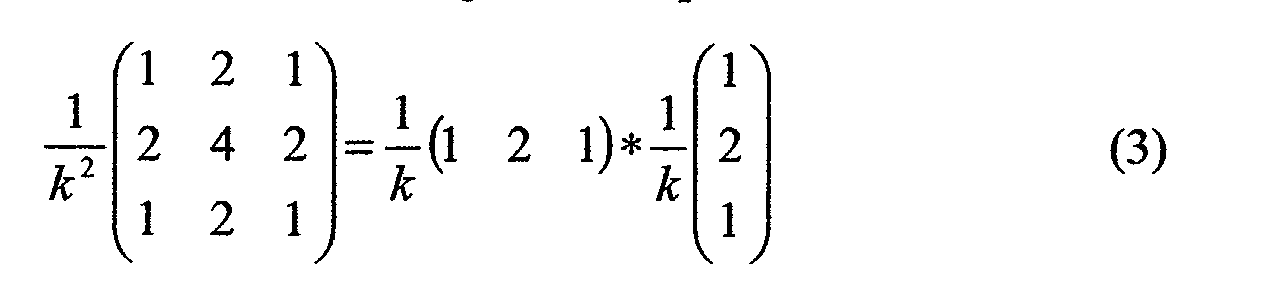
- the preferred implementation is a two-pass calculation using the one-dimensional kernels in a standard way. Since the data will then be subsampled by every third pixel, only every third pixel needs to be blurred. (This is true for both rows and columns.)
- a texture map is produced by thresholding the texture image (block 18). For 8-bit sRGB images, a threshold value of 60 was found to work well. Thus, for every texture image value greater than or equal to 60, the texture map value is set to one. Otherwise, the texture map value is set to zero. The result is a binary texture map. The locations where the map is set to one represents potential regions of texture. Locations that are set to zero represent, potentially, nontextured regions.
- a 5x5 dilate operation (block 52) is performed on the texture map (block 50). (This can be thought of as equivalent to a sparse 13x13 operation at the original pixel data resolution.)
- the texture map is binary, all that is required at each pixel location is to sum all of the map values in the support region and if the sum is greater than zero, then set the central map value to one.
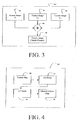
- the image pixel data is ready to be cleaned. This is first done by blurring the subsampled chroma data as modified by the texture map (block 22, FIG. 1). See FIG. 5. If a pixel's texture map value is zero (block 58), then the pixel's chroma values are left unaltered (block 60). For those pixels with the texture map values of one, the first step is to sum the values of the texture map within the support region (block 62). In block 62 the support region is left as a general n x n region. From an image processing artifact standpoint, n can be set to any odd value from 3 on up. The larger the value of n, the more noise cleaning occurs.
- n can be reduced to 5 or 3, with a corresponding reduction in noise cleaning capability. Having deciding on a value of n, then the corresponding number of pixels within the spider-shaped neighborhood will be 4 n - 3.
- S T the sum of the texture map values within the support region
- block 66 the sum of the texture map values within the support region
- block 70 the chroma averaging operation has one additional step.
- FIG. 7 is a flow chart of this chroma cleaning stage.
- two summing registers and a count register are first initialized in register initialization block 74.
- the absolute difference in chrominance between each neighboring pixel and the central pixel is computed in difference block 76.
- Both chroma channel values must be within a threshold value in order for the pixel to be included in the cleaning calculations in comparison block 78. If this condition is met, then the summing and counting registers are updated appropriately in register update block 80. For noisy images, a threshold value of 10 is sufficient. It should now be clear that the color pixels in the chrominance signals are selected and modified so that the averaged colored pixels have corresponding chrominance values to the chrominance values of the pixel to be noise-cleaned.
- Upsample block 26 upsamples the cleaned chroma values by a factor of three to return to the original pixel resolution (see FIG. 1).
- the term ''upsampling'' refers to resampling on a finer grid than is currently being used so as to produce more pixels. This is done using simple bilinear interpolation. Just as in the case of the blurring operation prior to downsampling, the bilinearinterpolation may be done as a two-pass operation of one-dimensional linear interpolations.
- the interpolating kernels are given in Eq 4. The pixel location being interpolated is marked with the brackets. The interpolation kernels are reflected about the horizontal or vertical axis in the standard manner as needed.
- the final step is to convert the image from U space back to RGB space (block 28) using Eq. 2.
- the result is an image with reduced color aliasing artifacts (block 30).
- a computer program product may include one or more storage medium, for example; magnetic storage media such as magnetic disk (such as a floppy disk) or magnetic tape; optical storage media such as optical disk, optical tape, or machine readable bar code; solid-state electronic storage devices such as random access memory (RAM), or read-only memory (ROM); or any other physical device or media employed to store a computer program having instructions for controlling one or more computers to practice the method according to the present invention.
- magnetic storage media such as magnetic disk (such as a floppy disk) or magnetic tape
- optical storage media such as optical disk, optical tape, or machine readable bar code
- solid-state electronic storage devices such as random access memory (RAM), or read-only memory (ROM); or any other physical device or media employed to store a computer program having instructions for controlling one or more computers to practice the method according to the present invention.
Landscapes
- Physics & Mathematics (AREA)
- General Physics & Mathematics (AREA)
- Engineering & Computer Science (AREA)
- Theoretical Computer Science (AREA)
- Image Processing (AREA)
- Facsimile Image Signal Circuits (AREA)
- Color Image Communication Systems (AREA)
- Processing Of Color Television Signals (AREA)
Abstract
Description



Claims (7)
- A method of reducing color aliasing artifacts from a color digital image having color pixels comprising the steps of:(a) providing luminance and chrominance signals from the color digital image;(b) using such luminance and chrominance signals to separate the image into textured and nontextured regions having boundaries;(c) downsampling the chrominance signals and texture region mapping;(d) producing cleaned chrominance signals in the textured regions in response to the boundaries of the textured region and chrominance signals;(e) producing cleaned chrominance signals in the nontextured regions in response to the chrominance signals;(f) upsampling the noise-cleaned chrominance signals; and(g) using the luminance and upsampled noise-cleaned chrominance signals to provide a color digital image having reduced color aliasing artifacts.
- The method of claim 1 wherein step (c) is provided a plurality of times to produce the reduced resolution color digital image.
- The method of claim 1 wherein step (d) the color pixels in the chrominance signals are selected so that color pixels to be averaged do not extend beyond the boundaries of the textured region.
- The method of claim 1 wherein step (e) the color pixels in the chrominance signals are selected so that the averaged colored pixels have corresponding chrominance values to the chrominance values of the pixel to be noise-cleaned.
- The method of claim 1 wherein step (f) is provided a plurality of times to produce an original resolution color digital image.
- In a method for image processing, a color digital image and which includes minimizing color aliasing artifacts from a processed color digital image comprising the steps of:(a) image processing an input color digital image to produce a new color digital image that is modified with respect to the input color digital image;(b) reducing the number of color pixels in the input color digital image or the new color digital image to provide at least one lower resolution color digital image;(c) converting the lower resolution color digital image into a color space having luminance and chrominance content;(d) reducing aliasing artifacts in the chrominance content of the lower resolution color digital image by averaging chrominance values in a neighborhood of a color pixel of interest, wherein the color pixels averaged adjacent the color pixel of interest are related to the degree of image texture within the neighborhood;(e) interpolating the aliasing reduced chrominance signal to a higher resolution; and(f) using the original luminance signal and the interpolated chrominance signal to provide a color digital image which is either the input color digital image or the new color digital image so that the processed digital image has reduced color aliasing artifacts.
- A computer program product which practices the method of claim 1.
Applications Claiming Priority (2)
| Application Number | Priority Date | Filing Date | Title |
|---|---|---|---|
| US10/237,947 US6927804B2 (en) | 2002-09-09 | 2002-09-09 | Reducing color aliasing artifacts from color digital images |
| US237947 | 2002-09-09 |
Publications (2)
| Publication Number | Publication Date |
|---|---|
| EP1396817A2 true EP1396817A2 (en) | 2004-03-10 |
| EP1396817A3 EP1396817A3 (en) | 2011-05-04 |
Family
ID=31715340
Family Applications (1)
| Application Number | Title | Priority Date | Filing Date |
|---|---|---|---|
| EP03077726A Withdrawn EP1396817A3 (en) | 2002-09-09 | 2003-09-01 | Reducing color aliasing artifacts from color digital images |
Country Status (3)
| Country | Link |
|---|---|
| US (1) | US6927804B2 (en) |
| EP (1) | EP1396817A3 (en) |
| JP (1) | JP2004129229A (en) |
Cited By (2)
| Publication number | Priority date | Publication date | Assignee | Title |
|---|---|---|---|---|
| EP1411471A3 (en) * | 2002-10-15 | 2011-04-27 | Eastman Kodak Company | Removing color aliasing artifacts from color digital images |
| US20120033275A1 (en) * | 2010-08-05 | 2012-02-09 | Conexant Systems, Inc. | Systems and methods for color defringing |
Families Citing this family (12)
| Publication number | Priority date | Publication date | Assignee | Title |
|---|---|---|---|---|
| CN101238714B (en) * | 2005-08-12 | 2012-03-28 | Nxp股份有限公司 | Digital image stabilization method and system |
| US8482625B2 (en) * | 2005-11-16 | 2013-07-09 | Hewlett-Packard Development Company, L.P. | Image noise estimation based on color correlation |
| US8233748B2 (en) * | 2007-07-20 | 2012-07-31 | Samsung Electronics Co., Ltd. | Image-resolution-improvement apparatus and method |
| US8588541B2 (en) * | 2008-09-24 | 2013-11-19 | Nikon Corporation | Method and device for image deblurring using joint bilateral filtering |
| US8810698B2 (en) * | 2009-10-07 | 2014-08-19 | Panasonic Intellectual Property Corporation Of America | Two sided solid state image sensor and an image capture device |
| TWI394434B (en) * | 2009-12-30 | 2013-04-21 | Altek Corp | The method of eliminating the color dislocation of digital images |
| US8571343B2 (en) * | 2011-03-01 | 2013-10-29 | Sharp Laboratories Of America, Inc. | Methods and systems for document-image correction |
| US9288484B1 (en) | 2012-08-30 | 2016-03-15 | Google Inc. | Sparse coding dictionary priming |
| US9300906B2 (en) | 2013-03-29 | 2016-03-29 | Google Inc. | Pull frame interpolation |
| US9286653B2 (en) | 2014-08-06 | 2016-03-15 | Google Inc. | System and method for increasing the bit depth of images |
| US9153017B1 (en) | 2014-08-15 | 2015-10-06 | Google Inc. | System and method for optimized chroma subsampling |
| KR102584523B1 (en) | 2016-11-16 | 2023-10-05 | 한화비전 주식회사 | Method and apparatus for reducing color moire, and image processing apparatus using the method |
Family Cites Families (5)
| Publication number | Priority date | Publication date | Assignee | Title |
|---|---|---|---|---|
| US5864342A (en) * | 1995-08-04 | 1999-01-26 | Microsoft Corporation | Method and system for rendering graphical objects to image chunks |
| US20020176113A1 (en) * | 2000-09-21 | 2002-11-28 | Edgar Albert D. | Dynamic image correction and imaging systems |
| US6804392B1 (en) | 2000-10-16 | 2004-10-12 | Eastman Kodak Company | Removing color aliasing artifacts from color digital images |
| JP2004524729A (en) * | 2000-12-12 | 2004-08-12 | シャープ株式会社 | Display resolution enhancement method and system using sub-pixel sampling and visual distortion filtering |
| US7084906B2 (en) * | 2002-10-15 | 2006-08-01 | Eastman Kodak Company | Reducing computation time in removing color aliasing artifacts from color digital images |
-
2002
- 2002-09-09 US US10/237,947 patent/US6927804B2/en not_active Expired - Lifetime
-
2003
- 2003-08-12 JP JP2003207325A patent/JP2004129229A/en active Pending
- 2003-09-01 EP EP03077726A patent/EP1396817A3/en not_active Withdrawn
Cited By (4)
| Publication number | Priority date | Publication date | Assignee | Title |
|---|---|---|---|---|
| EP1411471A3 (en) * | 2002-10-15 | 2011-04-27 | Eastman Kodak Company | Removing color aliasing artifacts from color digital images |
| US20120033275A1 (en) * | 2010-08-05 | 2012-02-09 | Conexant Systems, Inc. | Systems and methods for color defringing |
| WO2012019170A1 (en) * | 2010-08-05 | 2012-02-09 | Conexant Systems, Inc., A Delaware Corporation | Systems and methods for color defringing |
| US8477394B2 (en) | 2010-08-05 | 2013-07-02 | Conexant Systems, Inc. | Systems and methods for color defringing |
Also Published As
| Publication number | Publication date |
|---|---|
| EP1396817A3 (en) | 2011-05-04 |
| US20040046894A1 (en) | 2004-03-11 |
| JP2004129229A (en) | 2004-04-22 |
| US6927804B2 (en) | 2005-08-09 |
Similar Documents
| Publication | Publication Date | Title |
|---|---|---|
| EP1411471B1 (en) | Removing color aliasing artifacts from color digital images | |
| US6934056B2 (en) | Noise cleaning and interpolating sparsely populated color digital image using a variable noise cleaning kernel | |
| EP1093087B1 (en) | Removing chroma noise from digital images by using variable shape pixel neighborhood regions | |
| US6927804B2 (en) | Reducing color aliasing artifacts from color digital images | |
| EP2089848B1 (en) | Noise reduction of panchromatic and color image | |
| EP2130176B1 (en) | Edge mapping using panchromatic pixels | |
| CN102362501B (en) | Method for modifying color and panchromatic channel CFA image | |
| US20020118887A1 (en) | Multiresolution based method for removing noise from digital images | |
| EP1202220B1 (en) | Method for removing color aliasing artifacts from color digital images | |
| US9148593B2 (en) | Advanced noise reduction in digital cameras | |
| JP2002503894A (en) | Noise removal algorithm based on new edge detection | |
| US20110242371A1 (en) | Advanced noise reduction in digital cameras | |
| US20200219229A1 (en) | Edge-Aware Upscaling for Improved Screen Content Quality | |
| JP2004040247A (en) | Image processing apparatus and control method thereof | |
| JP2008527861A (en) | Noise removal from scattered color digital images | |
| Kim et al. | On recent results in demosaicing of samsung 108mp cmos sensor using deep learning | |
| EP1083737A2 (en) | Removing color moire patterns from digital images having known chromaticities | |
| US6795586B1 (en) | Noise cleaning and interpolating sparsely populated color digital image | |
| CN118411311A (en) | Image sharpening method, system, storage medium and electronic equipment | |
| KR100839922B1 (en) | Apparatus and method for removing color noise using adaptive mean filter | |
| Saito et al. | Demosaicing method using the extended color total-variation regularization | |
| KR100192777B1 (en) | Median filter having multiple window size | |
| Hossain et al. | AN EFFICIENT APPROACH OF IMAGE RESTORATION USING MEAN INTENSITY CORRELATION OF NEIGHBORING PIXELS |
Legal Events
| Date | Code | Title | Description |
|---|---|---|---|
| PUAI | Public reference made under article 153(3) epc to a published international application that has entered the european phase |
Free format text: ORIGINAL CODE: 0009012 |
|
| AK | Designated contracting states |
Kind code of ref document: A2 Designated state(s): AT BE BG CH CY CZ DE DK EE ES FI FR GB GR HU IE IT LI LU MC NL PT RO SE SI SK TR |
|
| AX | Request for extension of the european patent |
Extension state: AL LT LV MK |
|
| PUAL | Search report despatched |
Free format text: ORIGINAL CODE: 0009013 |
|
| AK | Designated contracting states |
Kind code of ref document: A3 Designated state(s): AT BE BG CH CY CZ DE DK EE ES FI FR GB GR HU IE IT LI LU MC NL PT RO SE SI SK TR |
|
| AX | Request for extension of the european patent |
Extension state: AL LT LV MK |
|
| RIC1 | Information provided on ipc code assigned before grant |
Ipc: G06T 5/00 20060101AFI20110328BHEP |
|
| 17P | Request for examination filed |
Effective date: 20111020 |
|
| AKX | Designation fees paid |
Designated state(s): DE FR GB |
|
| RAP1 | Party data changed (applicant data changed or rights of an application transferred) |
Owner name: INTELLECTUAL VENTURES FUND 83 LLC |
|
| STAA | Information on the status of an ep patent application or granted ep patent |
Free format text: STATUS: THE APPLICATION IS DEEMED TO BE WITHDRAWN |
|
| 18D | Application deemed to be withdrawn |
Effective date: 20140201 |