EP1396628A2 - Fuel injection system for internal combustion engine - Google Patents
Fuel injection system for internal combustion engine Download PDFInfo
- Publication number
- EP1396628A2 EP1396628A2 EP03018843A EP03018843A EP1396628A2 EP 1396628 A2 EP1396628 A2 EP 1396628A2 EP 03018843 A EP03018843 A EP 03018843A EP 03018843 A EP03018843 A EP 03018843A EP 1396628 A2 EP1396628 A2 EP 1396628A2
- Authority
- EP
- European Patent Office
- Prior art keywords
- fuel injection
- upstream
- intake temperature
- correction factor
- valve
- Prior art date
- Legal status (The legal status is an assumption and is not a legal conclusion. Google has not performed a legal analysis and makes no representation as to the accuracy of the status listed.)
- Granted
Links
Images


Classifications
-
- F—MECHANICAL ENGINEERING; LIGHTING; HEATING; WEAPONS; BLASTING
- F02—COMBUSTION ENGINES; HOT-GAS OR COMBUSTION-PRODUCT ENGINE PLANTS
- F02D—CONTROLLING COMBUSTION ENGINES
- F02D41/00—Electrical control of supply of combustible mixture or its constituents
- F02D41/30—Controlling fuel injection
- F02D41/3094—Controlling fuel injection the fuel injection being effected by at least two different injectors, e.g. one in the intake manifold and one in the cylinder
-
- F—MECHANICAL ENGINEERING; LIGHTING; HEATING; WEAPONS; BLASTING
- F02—COMBUSTION ENGINES; HOT-GAS OR COMBUSTION-PRODUCT ENGINE PLANTS
- F02D—CONTROLLING COMBUSTION ENGINES
- F02D41/00—Electrical control of supply of combustible mixture or its constituents
- F02D41/30—Controlling fuel injection
- F02D41/32—Controlling fuel injection of the low pressure type
-
- F—MECHANICAL ENGINEERING; LIGHTING; HEATING; WEAPONS; BLASTING
- F02—COMBUSTION ENGINES; HOT-GAS OR COMBUSTION-PRODUCT ENGINE PLANTS
- F02M—SUPPLYING COMBUSTION ENGINES IN GENERAL WITH COMBUSTIBLE MIXTURES OR CONSTITUENTS THEREOF
- F02M69/00—Low-pressure fuel-injection apparatus ; Apparatus with both continuous and intermittent injection; Apparatus injecting different types of fuel
- F02M69/04—Injectors peculiar thereto
- F02M69/042—Positioning of injectors with respect to engine, e.g. in the air intake conduit
- F02M69/043—Positioning of injectors with respect to engine, e.g. in the air intake conduit for injecting into the intake conduit upstream of an air throttle valve
-
- F—MECHANICAL ENGINEERING; LIGHTING; HEATING; WEAPONS; BLASTING
- F02—COMBUSTION ENGINES; HOT-GAS OR COMBUSTION-PRODUCT ENGINE PLANTS
- F02M—SUPPLYING COMBUSTION ENGINES IN GENERAL WITH COMBUSTIBLE MIXTURES OR CONSTITUENTS THEREOF
- F02M69/00—Low-pressure fuel-injection apparatus ; Apparatus with both continuous and intermittent injection; Apparatus injecting different types of fuel
- F02M69/04—Injectors peculiar thereto
- F02M69/042—Positioning of injectors with respect to engine, e.g. in the air intake conduit
- F02M69/044—Positioning of injectors with respect to engine, e.g. in the air intake conduit for injecting into the intake conduit downstream of an air throttle valve
-
- F—MECHANICAL ENGINEERING; LIGHTING; HEATING; WEAPONS; BLASTING
- F02—COMBUSTION ENGINES; HOT-GAS OR COMBUSTION-PRODUCT ENGINE PLANTS
- F02M—SUPPLYING COMBUSTION ENGINES IN GENERAL WITH COMBUSTIBLE MIXTURES OR CONSTITUENTS THEREOF
- F02M69/00—Low-pressure fuel-injection apparatus ; Apparatus with both continuous and intermittent injection; Apparatus injecting different types of fuel
- F02M69/44—Low-pressure fuel-injection apparatus ; Apparatus with both continuous and intermittent injection; Apparatus injecting different types of fuel characterised by means for supplying extra fuel to the engine on sudden air throttle opening, e.g. at acceleration
-
- F—MECHANICAL ENGINEERING; LIGHTING; HEATING; WEAPONS; BLASTING
- F02—COMBUSTION ENGINES; HOT-GAS OR COMBUSTION-PRODUCT ENGINE PLANTS
- F02D—CONTROLLING COMBUSTION ENGINES
- F02D41/00—Electrical control of supply of combustible mixture or its constituents
- F02D41/20—Output circuits, e.g. for controlling currents in command coils
- F02D2041/2068—Output circuits, e.g. for controlling currents in command coils characterised by the circuit design or special circuit elements
- F02D2041/2082—Output circuits, e.g. for controlling currents in command coils characterised by the circuit design or special circuit elements the circuit being adapted to distribute current between different actuators or recuperate energy from actuators
-
- F—MECHANICAL ENGINEERING; LIGHTING; HEATING; WEAPONS; BLASTING
- F02—COMBUSTION ENGINES; HOT-GAS OR COMBUSTION-PRODUCT ENGINE PLANTS
- F02D—CONTROLLING COMBUSTION ENGINES
- F02D2200/00—Input parameters for engine control
- F02D2200/02—Input parameters for engine control the parameters being related to the engine
- F02D2200/04—Engine intake system parameters
- F02D2200/0404—Throttle position
-
- F—MECHANICAL ENGINEERING; LIGHTING; HEATING; WEAPONS; BLASTING
- F02—COMBUSTION ENGINES; HOT-GAS OR COMBUSTION-PRODUCT ENGINE PLANTS
- F02D—CONTROLLING COMBUSTION ENGINES
- F02D2200/00—Input parameters for engine control
- F02D2200/02—Input parameters for engine control the parameters being related to the engine
- F02D2200/04—Engine intake system parameters
- F02D2200/0406—Intake manifold pressure
-
- F—MECHANICAL ENGINEERING; LIGHTING; HEATING; WEAPONS; BLASTING
- F02—COMBUSTION ENGINES; HOT-GAS OR COMBUSTION-PRODUCT ENGINE PLANTS
- F02D—CONTROLLING COMBUSTION ENGINES
- F02D2200/00—Input parameters for engine control
- F02D2200/02—Input parameters for engine control the parameters being related to the engine
- F02D2200/04—Engine intake system parameters
- F02D2200/0414—Air temperature
Definitions
- the present invention relates to a fuel injection system for an internal combustion engine, and more particularly to a fuel injection system in which injection valves have been provided on the upstream side and on the downstream side respectively with a throttle valve interposed therebetween.
- the volumetric efficiency is improved because heat is taken from intake air when injection fuel vaporizes. Therefore, the engine output can be increased as compared with when the fuel injection valve is provided downstream from the throttle valve.
- a distance between its fuel injection port and the combustion chamber inevitably becomes longer, a response lag occurs in fuel transport as compared with when the fuel injection valve is provided downstream from the throttle valve, and this causes the drive-ability to be deteriorated.
- Fig. 7 is a cross-sectional view showing a major portion of a conventional internal combustion engine in which two fuel injection valves have been arranged, and with a throttle valve 52 of an intake pipe 51 interposed, there are arranged a downstream fuel injection valve 50a on the side portion of the downstream side (engine side) and an upstream fuel injection valve 50b on the upstream side (air cleaner side) .
- a lower end portion of the intake pipe 51 is connected to an intake passage 52, and an intake port 53 facing a combustion chamber of this intake passage 52 is opened and closed by an intake valve 54.
- the fuel injection quantity of each fuel injection valve is determined with plural parameters including the throttle opening as a function, but since volumetric efficiency within the combustion chamber is dependent on the intake temperature, an electronic controlled fuel injection system detects the intake temperature TA to control in such a manner that the injection quantity is relatively reduced as the intake temperature TA becomes higher.
- the intake temperature TA is preferably detected immediately before the combustion chamber, but since when a temperature sensor is provided at the portion concerned, intake efficiency of an air-fuel mixture into the combustion chamber is deteriorated, in an engine in which two fuel inj ection valves are arranged, the temperature sensor is often provided on the upstream side from the fuel injection area of the upstream fuel injection valve 50b.
- a fuel injection system for an internal combustion engine having an intake pipe equipped with a throttle valve, an upstream fuel injection valve provided upstream from the throttle valve and a downstream fuel injection valve provided downstream from the throttle valve, comprising: means for determining fuel injection quantity due to the upstream and downstream fuel injection valves; means for detecting intake temperature TA on the upstream side from an injection area of the upstream fuel injection valve; means for seeking an intake temperature correction factor KTA on the basis of the intake temperature TA and a fuel injection quantity of the upstream fuel inj ection valve; and means for correcting at least one of the fuel injection quantities due to the upstream and downstream fuel injection valves on the basis of the intake temperature correction factor KTA.
- the intake temperature correction factor KTA can be sought as a function of the fuel injection quantity of the upstream fuel injection valve. Accordingly, if it is arranged in such a manner that the intake temperature correction factor KTA becomes relatively large as the fuel injection quantity of the upstream fuel injection valve increases, a drop in the intake temperature due to upstream fuel injection will be properly compensated for, and therefore, it becomes possible to supply an optimum quantity of fuel to the intake temperature.
- FIG. 1 is a general block diagram showing a fuel inj ection system according to one embodiment of the present invention, and on a combustion chamber 21 of the engine 20, there are opened an intake port 22 and an exhaust port 23.
- Each port 22 and 23 is provided with an intake valve 24 and an exhaust valve 25 respectively, and an ignition plug 26 is provided.
- a throttle valve 28 for adjusting intake air quantity in accordance with its opening ⁇ TH, a throttle sensor 5 for detecting the opening ⁇ TH and a vacuum sensor 6 for detecting intake manifold vacuum PB.
- an air cleaner 29 At a terminal of the intake passage 27, there is provided an air cleaner 29. Within the air cleaner 29, there is provided an air filter 30, and open air is taken into the intake passage 27 through this air filter 30.
- an engine speed sensor 4 for detecting engine speed NE on the basis of a rotation angle of a crank.
- a vehicle speed sensor 7 for detecting vehicle speed V.
- a water temperature sensor 3 for detecting cooling water temperature TW representing the engine temperature.
- An ECU (Engine Control Unit) 1 includes a fuel injection control unit 10 and an ignition timing control unit 11.
- the fuel injection control unit 10 outputs, on the basis of signals (process values) obtained by detecting by each of the above-described sensors, injection signals Qupper and Qlower to each injection valve 8a, 8b on the upstream and downstream sides.
- Each of these inj ection signals is a pulse signal having pulse width responsive to the injection quantity, and each injection valve 8a, 8b is opened by time corresponding to this pulse width to inject the fuel.
- the ignition timing control unit 11 controls ignition timing of an ignition plug 26.
- Fig. 2 is a functional block diagram for the fuel injection control unit 10, and the same symbols as in the foregoing represent the same or equal portions.
- a total injection quantity determination unit 101 determines a total quantity Qtotal of fuel to be injected from each fuel injection valve 8a, 8b on the upstream and downstream sides on the basis of the engine speed NE, the throttle opening ⁇ TH and intake pressure PB.
- An injection rate determination unit 102 refers to an injection rate table on the basis of the engine speedNE and throttle opening ⁇ TH to determine an inj ection rate Rupper of the upstream injection valve 8a.
- An injection rate Rlower of the downstream injection valve 8b is determined as (1 - Rupper).
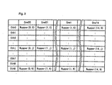
- Fig. 3 is a view showing an example of the injection rate table, and in the present embodiment, an injection rate map is constituted with 15 items (Cne00 to Cne14) as a reference as the engine speed NE, and with 10 items (Cth0 to Cth9) as a reference as the throttle opening ⁇ TH, and the injection rate Rupperof the upstream injection valve 8a is registered in advance at each combination of each engine speed NE and the throttle opening ⁇ TH.
- the injection rate determination unit 102 determines an injection rate Rupper corresponding to the engine speed NE and the throttle opening ⁇ TH that have been detected, by means of the four-point interpolation on the injection rate map.
- a correction factor calculation unit 103 refers to a data table on the basis of the intake temperature TA and the cooling water temperature TW that have been detected to seek various correction factors including an intake temperature correction factor KTA and a cooling water temperature correction factor KTW.
- a TA/KTAL table to be described later is referred to and a correction factor KTAL for a light load corresponding to the intake temperature TA is calculated.
- a TA/KTAH table to be described later is referred to, and a correction factor KTAH for a heavy load corresponding to the intake temperature TA is calculated.
- a TA/KTA2 table to be described later is referred to, and a correction factor KTA2 for upstream and downstream injection corresponding to the intake temperature TA is calculated.
- Fig. 5 is a view showing the contents of each of the above-described tables schematically and superimposed, and for each intake temperature TA, each correction factor KTAL, KTAH and KTA2 corresponding thereto has been registered.
- each correction factor for the intake temperature TA has been selected so as to indicate a tendency of KTAL ⁇ KTAH ⁇ KTA2.
- a relationship between the intake temperature TA and each correction factor has been registered only with nine items of the intake temperature TA, and any other relationships can be sought by interpolation.
- the engine speed NE is compared with a predetermined reference speed.
- the engine speed NE is compared with an idle speed, and when the engine speed NE becomes lower than the idle speed, the sequence will proceed to a step S15.
- the throttle opening ⁇ th is compared with a predetermined reference opening.
- the throttle opening ⁇ th is compared with the idle opening and when the throttle opening ⁇ th becomes lower than the idle opening, the sequence will proceed to a step S16.
- the correction factor for a light load KTAL sought in the step S11 will be adopted as the intake temperature correction factor KTA, and a light load flag FL will be set.
- the sequence will proceed to a step S17 to refer to the light load flag FL. If the light load flag FL has been set, the sequence will proceed to a step S18, and the correction factor for a heavy load KTAH sought in the step S12 will be adopted as the intake temperature correction factor KTA, and the light load flag FL will be reset.
- step S17 if the light load flag FL has not been set, the sequence will proceed to a step S19, and an upstream injection quantity Qupper which is determined by an upstream injection quantity determination unit 1051 to be described later will be compared with a predetermined reference injection quantity Qref . If Qupper ⁇ Qref, the sequence will proceed to a step S20 because a drop in intake temperature due to the upstream injection is low, and a correction factor for a heavy load KTAH sought in the step S12 will be registered to a target correction factor KTAtg.
- a differential between the target correction factor KTAtg and the present intake temperature correction factor KTA there is sought a differential between the target correction factor KTAtg and the present intake temperature correction factor KTA, and this differential is compared with the maximum correction quantity ⁇ KTAmax. If the differential is smaller than the maximum correction quantity ⁇ KTAmax, the target correction factor KTAtg will be adopted as it is as the intake temperature correction factor KTA in a step S26.
- the sequence will proceed to a step S23 to compare the target correction factor KTAtg with the present intake temperature correction factor KTA. If the target correction factor KTAtg is smaller than the intake temperature correction factor KTA, in a step S24, a value obtained by deducting the maximum correction quantity ⁇ KTAmax from the present intake temperature correction factor KTA will be adopted as a new intake temperature correction factor KTA. If the target correction factor KTAtg is larger than the intake temperature correction factor KTA, in a step S25, a sum of the present intake temperature correction factor KTA and the maximum correction quantity ⁇ KTAmax will be adopted as a new intake temperature correction factor KTA.
- the intake temperature correction factor is switched depending on the injection quantity due to the upstream injection valve, it becomes possible to accurately control the fuel injection even if the intake temperature varies in response to the inj ection quantity of the upstream injection valve.
- the injection quantity correction unit 104 corrects the inj ection quantity of each inj ection valve 8a, 8b during acceleration, when abruptly closing the throttle opening ⁇ th and at otherwise time.
- the upstream injection quantity determination unit 1051 seeks a basic injection quantity of the upper injection valve 8a on the basis of the injection rate Rupper and the total injection quantity Qtotal, and multiplies this basic injection quantity by various correction factors including the correction factor KTA, KTW to determine the injection quantity Qupper of the upstream injection valve 8a.
- a downstream injection quantity determination unit 1052 determines the injection quantity Qlower of the downstream injection valve 8b on the basis of the upstream injection quantity Qupper and the total injection quantity Qtotal.
- This handling is executed by interruption due to a crank pulse in a predetermined stage.
- a step S10 the engine speed NE, the throttle opening ⁇ TH, the manifold air pressure PB, the intake temperature TA and the cooling water temperature TW are detected by each of the above-described sensors.
- a step S11 in the total injection quantity determination unit 101, total quantity Qtotal of fuel to be injected from each fuel injection valve 8a, 8b on the upstream side and on the downstream side is determined on the basis of the engine speed NE, the throttle opening ⁇ TH and the intake pressure PB.
- an injection rate table is referred to on the basis of the engine speed Ne and the throttle opening ⁇ TH, and an inj ection rate Rupper of the upstream injection valve 8a is determined.
- an injection signal having pulse width responsive to each of the injection quantity Qupper, Qlower is outputted to each injection valve 8a, 8b at predetermined timing synchronized to the crank angle to inject fuel from each injection valve 8a, 8b.
- the intake temperature correction factor KTA can be sought as a function of the fuel injection quantity of the upstream fuel injection valve. Accordingly, if it is arranged in such a manner that the intake temperature correction factor KTA becomes relatively large as the fuel inj ection quantity of the upstream fuel inj ection valve increases, a drop in the intake temperature due to upstream fuel injection will be properly compensated for, and therefore, it becomes possible to supply an optimum quantity of fuel to the intake temperature.
- a fuel injection system for an internal combustion engine capable of supplying, in structure in which fuel injection valves are arranged on the upstream side and on the downstream side of the throttle valve respectively, an optimum quantity of fuel to the intake temperature.
- a fuel injection system for an internal combustion engine having an upstream fuel injection valve provided upstream from the throttle valve and a downstream fuel injection valve provided downstream therefrom, including: means 101, 102, 105 for determining fuel injection quantity of the upstream and downstream fuel injection valves; a sensor 2 for detecting intake temperature TA on the upstream side from an injection area of the upstream fuel injection valve; and means 103 for seeking an intake temperature correction factor KTA on the basis of the intake temperature TA and a fuel injection quantity of the upstream fuel injection valve, wherein there is corrected at least one of the fuel injection quantities due to the upstream and downstream fuel injection valves on the basis of the intake temperature correction factor KTA.
Landscapes
- Engineering & Computer Science (AREA)
- Chemical & Material Sciences (AREA)
- Combustion & Propulsion (AREA)
- Mechanical Engineering (AREA)
- General Engineering & Computer Science (AREA)
- Electrical Control Of Air Or Fuel Supplied To Internal-Combustion Engine (AREA)
- Combined Controls Of Internal Combustion Engines (AREA)
Abstract
Description
Solution: A fuel injection system for an internal combustion engine, having an upstream fuel injection valve provided upstream from the throttle valve and a downstream fuel injection valve provided downstream therefrom, including: means 101, 102, 105 for determining fuel injection quantity of the upstream and downstream fuel injection valves; a
Claims (3)
- A fuel injection system for an internal combustion engine (20) having an intake pipe equipped with a throttle valve (28), an upstream fuel injection valve (8a) provided upstream from said throttle valve (28) and a downstream fuel injection valve (8b) provided downstream from said throttle valve (28), comprising:means (101, 102, 105) for determining fuel injection quantities due to said upstream and downstream fuel injection valves (8a, 8b);means (2) for detecting intake temperature (TA) on the upstream side from an injection area of said upstream fuel injection valve (8a);means (103) for seeking an intake temperature correction factor (KTA) on the basis of said intake temperature (TA) and a fuel injection quantity of said upstream fuel injection valve (8a); andmeans (104) for correcting at least one of said fuel injection quantities due to said upstream and downstream fuel injection valves (8a, 8b) on the basis of said intake temperature correction factor (KTA).
- The fuel injection system for an internal combustion engine (20) according to claim 1, characterized in that said intake temperature correction factor (KTA) is sought irrespective of said fuel injection quantity of said upstream fuel injection valve (8a) under a light load of said engine (20).
- The fuel injection system for an internal combustion engine (20) according to claim 1, characterized in that said intake temperature correction factor (KTA) becomes relatively high as the fuel injection quantity of said upstream fuel injection valve (8a) increases.
Applications Claiming Priority (2)
| Application Number | Priority Date | Filing Date | Title |
|---|---|---|---|
| JP2002258212 | 2002-09-03 | ||
| JP2002258212A JP3966463B2 (en) | 2002-09-03 | 2002-09-03 | Fuel injection device for internal combustion engine |
Publications (3)
| Publication Number | Publication Date |
|---|---|
| EP1396628A2 true EP1396628A2 (en) | 2004-03-10 |
| EP1396628A3 EP1396628A3 (en) | 2006-06-28 |
| EP1396628B1 EP1396628B1 (en) | 2010-11-17 |
Family
ID=31712296
Family Applications (1)
| Application Number | Title | Priority Date | Filing Date |
|---|---|---|---|
| EP03018843A Expired - Lifetime EP1396628B1 (en) | 2002-09-03 | 2003-08-19 | Fuel injection system for internal combustion engine |
Country Status (5)
| Country | Link |
|---|---|
| US (1) | US6941931B2 (en) |
| EP (1) | EP1396628B1 (en) |
| JP (1) | JP3966463B2 (en) |
| DE (1) | DE60334963D1 (en) |
| ES (1) | ES2354260T3 (en) |
Family Cites Families (6)
| Publication number | Priority date | Publication date | Assignee | Title |
|---|---|---|---|---|
| JPS6045300B2 (en) * | 1977-10-07 | 1985-10-08 | 日産自動車株式会社 | Internal combustion engine fuel supply system |
| US4825834A (en) * | 1986-12-10 | 1989-05-02 | Honda Giken Kogyo Kabushiki Kaisha | Fuel supply control method for internal combustion engines |
| JPH04183949A (en) * | 1990-11-19 | 1992-06-30 | Mazda Motor Corp | Engine fuel control device |
| JPH0626391A (en) * | 1992-07-08 | 1994-02-01 | Mazda Motor Corp | Engine fuel controller |
| AUPM632494A0 (en) * | 1994-06-21 | 1994-07-14 | Biocom Pty Ltd | Auxiliary injector |
| JP3886193B2 (en) * | 1997-01-14 | 2007-02-28 | 本田技研工業株式会社 | Fuel injection device |
-
2002
- 2002-09-03 JP JP2002258212A patent/JP3966463B2/en not_active Expired - Fee Related
-
2003
- 2003-08-19 DE DE60334963T patent/DE60334963D1/en not_active Expired - Lifetime
- 2003-08-19 ES ES03018843T patent/ES2354260T3/en not_active Expired - Lifetime
- 2003-08-19 EP EP03018843A patent/EP1396628B1/en not_active Expired - Lifetime
- 2003-08-22 US US10/645,600 patent/US6941931B2/en not_active Expired - Fee Related
Also Published As
| Publication number | Publication date |
|---|---|
| US20040065302A1 (en) | 2004-04-08 |
| US6941931B2 (en) | 2005-09-13 |
| JP3966463B2 (en) | 2007-08-29 |
| ES2354260T3 (en) | 2011-03-11 |
| JP2004092606A (en) | 2004-03-25 |
| DE60334963D1 (en) | 2010-12-30 |
| EP1396628A3 (en) | 2006-06-28 |
| EP1396628B1 (en) | 2010-11-17 |
Similar Documents
| Publication | Publication Date | Title |
|---|---|---|
| EP2458183B1 (en) | Apparatus for controlling internal combustion engine | |
| CN100357581C (en) | Four-stroked engine control device and control method | |
| US7100572B2 (en) | Fuel injection system and fuel injecting method for internal combustion engine | |
| CA2437329C (en) | Fuel injection system for internal combustion engine | |
| JP2008190342A (en) | Control device for internal combustion engine | |
| US6085729A (en) | Fuel injection control for engines responsive to fuel injection timing | |
| EP1396628B1 (en) | Fuel injection system for internal combustion engine | |
| CA2436968C (en) | Fuel injection system for internal combustion engine | |
| US6848428B2 (en) | Fuel injection control system for internal combustion engine | |
| JP4986895B2 (en) | Engine fuel injection control device | |
| JP4900347B2 (en) | Control device for internal combustion engine | |
| JP4170773B2 (en) | Fuel injection timing control device for in-cylinder injection type engine | |
| EP3075991B1 (en) | Control device for internal combustion engine | |
| JP2010127122A (en) | Supercharging pressure control device of cylinder injection type internal combustion engine | |
| US20020117147A1 (en) | Ignition timing control apparatus for internal combustion engine | |
| JP2004100589A (en) | Fuel injection device for internal combustion engine | |
| JP2005147123A (en) | Gas fuel engine | |
| JPH02104934A (en) | Fuel injection device for engine | |
| JP2005330861A (en) | Control device for internal combustion engine | |
| JP2011140920A (en) | Fuel control device for internal combustion engine | |
| JP2013142338A (en) | Internal combustion engine control device |
Legal Events
| Date | Code | Title | Description |
|---|---|---|---|
| PUAI | Public reference made under article 153(3) epc to a published international application that has entered the european phase |
Free format text: ORIGINAL CODE: 0009012 |
|
| AK | Designated contracting states |
Kind code of ref document: A2 Designated state(s): AT BE BG CH CY CZ DE DK EE ES FI FR GB GR HU IE IT LI LU MC NL PT RO SE SI SK TR |
|
| AX | Request for extension of the european patent |
Extension state: AL LT LV MK |
|
| PUAL | Search report despatched |
Free format text: ORIGINAL CODE: 0009013 |
|
| AK | Designated contracting states |
Kind code of ref document: A3 Designated state(s): AT BE BG CH CY CZ DE DK EE ES FI FR GB GR HU IE IT LI LU MC NL PT RO SE SI SK TR |
|
| AX | Request for extension of the european patent |
Extension state: AL LT LV MK |
|
| 17P | Request for examination filed |
Effective date: 20060622 |
|
| AKX | Designation fees paid |
Designated state(s): DE ES FR GB IT |
|
| GRAP | Despatch of communication of intention to grant a patent |
Free format text: ORIGINAL CODE: EPIDOSNIGR1 |
|
| GRAS | Grant fee paid |
Free format text: ORIGINAL CODE: EPIDOSNIGR3 |
|
| GRAA | (expected) grant |
Free format text: ORIGINAL CODE: 0009210 |
|
| RIN1 | Information on inventor provided before grant (corrected) |
Inventor name: YUHARA, TOMOMI Inventor name: WATANABE, TSUGUO |
|
| AK | Designated contracting states |
Kind code of ref document: B1 Designated state(s): DE ES FR GB IT |
|
| REG | Reference to a national code |
Ref country code: GB Ref legal event code: FG4D |
|
| REF | Corresponds to: |
Ref document number: 60334963 Country of ref document: DE Date of ref document: 20101230 Kind code of ref document: P |
|
| REG | Reference to a national code |
Ref country code: ES Ref legal event code: FG2A Effective date: 20110301 |
|
| PLBE | No opposition filed within time limit |
Free format text: ORIGINAL CODE: 0009261 |
|
| STAA | Information on the status of an ep patent application or granted ep patent |
Free format text: STATUS: NO OPPOSITION FILED WITHIN TIME LIMIT |
|
| 26N | No opposition filed |
Effective date: 20110818 |
|
| REG | Reference to a national code |
Ref country code: DE Ref legal event code: R097 Ref document number: 60334963 Country of ref document: DE Effective date: 20110818 |
|
| REG | Reference to a national code |
Ref country code: FR Ref legal event code: PLFP Year of fee payment: 13 |
|
| PGFP | Annual fee paid to national office [announced via postgrant information from national office to epo] |
Ref country code: ES Payment date: 20150713 Year of fee payment: 13 Ref country code: GB Payment date: 20150819 Year of fee payment: 13 Ref country code: DE Payment date: 20150811 Year of fee payment: 13 |
|
| PGFP | Annual fee paid to national office [announced via postgrant information from national office to epo] |
Ref country code: FR Payment date: 20150629 Year of fee payment: 13 |
|
| PGFP | Annual fee paid to national office [announced via postgrant information from national office to epo] |
Ref country code: IT Payment date: 20150827 Year of fee payment: 13 |
|
| REG | Reference to a national code |
Ref country code: DE Ref legal event code: R119 Ref document number: 60334963 Country of ref document: DE |
|
| GBPC | Gb: european patent ceased through non-payment of renewal fee |
Effective date: 20160819 |
|
| REG | Reference to a national code |
Ref country code: FR Ref legal event code: ST Effective date: 20170428 |
|
| PG25 | Lapsed in a contracting state [announced via postgrant information from national office to epo] |
Ref country code: FR Free format text: LAPSE BECAUSE OF NON-PAYMENT OF DUE FEES Effective date: 20160831 Ref country code: GB Free format text: LAPSE BECAUSE OF NON-PAYMENT OF DUE FEES Effective date: 20160819 Ref country code: DE Free format text: LAPSE BECAUSE OF NON-PAYMENT OF DUE FEES Effective date: 20170301 |
|
| PG25 | Lapsed in a contracting state [announced via postgrant information from national office to epo] |
Ref country code: IT Free format text: LAPSE BECAUSE OF NON-PAYMENT OF DUE FEES Effective date: 20160819 |
|
| PG25 | Lapsed in a contracting state [announced via postgrant information from national office to epo] |
Ref country code: ES Free format text: LAPSE BECAUSE OF NON-PAYMENT OF DUE FEES Effective date: 20160820 |
|
| REG | Reference to a national code |
Ref country code: ES Ref legal event code: FD2A Effective date: 20181128 |