EP1396619A1 - Supercharging system for an internal combustion engine - Google Patents
Supercharging system for an internal combustion engine Download PDFInfo
- Publication number
- EP1396619A1 EP1396619A1 EP02020006A EP02020006A EP1396619A1 EP 1396619 A1 EP1396619 A1 EP 1396619A1 EP 02020006 A EP02020006 A EP 02020006A EP 02020006 A EP02020006 A EP 02020006A EP 1396619 A1 EP1396619 A1 EP 1396619A1
- Authority
- EP
- European Patent Office
- Prior art keywords
- turbine
- charging system
- internal combustion
- combustion engine
- exhaust gas
- Prior art date
- Legal status (The legal status is an assumption and is not a legal conclusion. Google has not performed a legal analysis and makes no representation as to the accuracy of the status listed.)
- Withdrawn
Links
Images


Classifications
-
- F—MECHANICAL ENGINEERING; LIGHTING; HEATING; WEAPONS; BLASTING
- F01—MACHINES OR ENGINES IN GENERAL; ENGINE PLANTS IN GENERAL; STEAM ENGINES
- F01N—GAS-FLOW SILENCERS OR EXHAUST APPARATUS FOR MACHINES OR ENGINES IN GENERAL; GAS-FLOW SILENCERS OR EXHAUST APPARATUS FOR INTERNAL COMBUSTION ENGINES
- F01N3/00—Exhaust or silencing apparatus having means for purifying, rendering innocuous, or otherwise treating exhaust
- F01N3/08—Exhaust or silencing apparatus having means for purifying, rendering innocuous, or otherwise treating exhaust for rendering innocuous
- F01N3/10—Exhaust or silencing apparatus having means for purifying, rendering innocuous, or otherwise treating exhaust for rendering innocuous by thermal or catalytic conversion of noxious components of exhaust
- F01N3/105—General auxiliary catalysts, e.g. upstream or downstream of the main catalyst
-
- F—MECHANICAL ENGINEERING; LIGHTING; HEATING; WEAPONS; BLASTING
- F01—MACHINES OR ENGINES IN GENERAL; ENGINE PLANTS IN GENERAL; STEAM ENGINES
- F01N—GAS-FLOW SILENCERS OR EXHAUST APPARATUS FOR MACHINES OR ENGINES IN GENERAL; GAS-FLOW SILENCERS OR EXHAUST APPARATUS FOR INTERNAL COMBUSTION ENGINES
- F01N13/00—Exhaust or silencing apparatus characterised by constructional features ; Exhaust or silencing apparatus, or parts thereof, having pertinent characteristics not provided for in, or of interest apart from, groups F01N1/00 - F01N5/00, F01N9/00, F01N11/00
- F01N13/009—Exhaust or silencing apparatus characterised by constructional features ; Exhaust or silencing apparatus, or parts thereof, having pertinent characteristics not provided for in, or of interest apart from, groups F01N1/00 - F01N5/00, F01N9/00, F01N11/00 having two or more separate purifying devices arranged in series
- F01N13/0093—Exhaust or silencing apparatus characterised by constructional features ; Exhaust or silencing apparatus, or parts thereof, having pertinent characteristics not provided for in, or of interest apart from, groups F01N1/00 - F01N5/00, F01N9/00, F01N11/00 having two or more separate purifying devices arranged in series the purifying devices are of the same type
-
- F—MECHANICAL ENGINEERING; LIGHTING; HEATING; WEAPONS; BLASTING
- F01—MACHINES OR ENGINES IN GENERAL; ENGINE PLANTS IN GENERAL; STEAM ENGINES
- F01N—GAS-FLOW SILENCERS OR EXHAUST APPARATUS FOR MACHINES OR ENGINES IN GENERAL; GAS-FLOW SILENCERS OR EXHAUST APPARATUS FOR INTERNAL COMBUSTION ENGINES
- F01N3/00—Exhaust or silencing apparatus having means for purifying, rendering innocuous, or otherwise treating exhaust
- F01N3/08—Exhaust or silencing apparatus having means for purifying, rendering innocuous, or otherwise treating exhaust for rendering innocuous
- F01N3/10—Exhaust or silencing apparatus having means for purifying, rendering innocuous, or otherwise treating exhaust for rendering innocuous by thermal or catalytic conversion of noxious components of exhaust
- F01N3/18—Exhaust or silencing apparatus having means for purifying, rendering innocuous, or otherwise treating exhaust for rendering innocuous by thermal or catalytic conversion of noxious components of exhaust characterised by methods of operation; Control
- F01N3/20—Exhaust or silencing apparatus having means for purifying, rendering innocuous, or otherwise treating exhaust for rendering innocuous by thermal or catalytic conversion of noxious components of exhaust characterised by methods of operation; Control specially adapted for catalytic conversion ; Methods of operation or control of catalytic converters
- F01N3/2053—By-passing catalytic reactors, e.g. to prevent overheating
-
- F—MECHANICAL ENGINEERING; LIGHTING; HEATING; WEAPONS; BLASTING
- F02—COMBUSTION ENGINES; HOT-GAS OR COMBUSTION-PRODUCT ENGINE PLANTS
- F02B—INTERNAL-COMBUSTION PISTON ENGINES; COMBUSTION ENGINES IN GENERAL
- F02B37/00—Engines characterised by provision of pumps driven at least for part of the time by exhaust
- F02B37/004—Engines characterised by provision of pumps driven at least for part of the time by exhaust with exhaust drives arranged in series
-
- F—MECHANICAL ENGINEERING; LIGHTING; HEATING; WEAPONS; BLASTING
- F02—COMBUSTION ENGINES; HOT-GAS OR COMBUSTION-PRODUCT ENGINE PLANTS
- F02B—INTERNAL-COMBUSTION PISTON ENGINES; COMBUSTION ENGINES IN GENERAL
- F02B37/00—Engines characterised by provision of pumps driven at least for part of the time by exhaust
- F02B37/013—Engines characterised by provision of pumps driven at least for part of the time by exhaust with exhaust-driven pumps arranged in series
-
- F—MECHANICAL ENGINEERING; LIGHTING; HEATING; WEAPONS; BLASTING
- F02—COMBUSTION ENGINES; HOT-GAS OR COMBUSTION-PRODUCT ENGINE PLANTS
- F02B—INTERNAL-COMBUSTION PISTON ENGINES; COMBUSTION ENGINES IN GENERAL
- F02B37/00—Engines characterised by provision of pumps driven at least for part of the time by exhaust
- F02B37/12—Control of the pumps
- F02B37/16—Control of the pumps by bypassing charging air
- F02B37/162—Control of the pumps by bypassing charging air by bypassing, e.g. partially, intake air from pump inlet to pump outlet
-
- F—MECHANICAL ENGINEERING; LIGHTING; HEATING; WEAPONS; BLASTING
- F02—COMBUSTION ENGINES; HOT-GAS OR COMBUSTION-PRODUCT ENGINE PLANTS
- F02B—INTERNAL-COMBUSTION PISTON ENGINES; COMBUSTION ENGINES IN GENERAL
- F02B37/00—Engines characterised by provision of pumps driven at least for part of the time by exhaust
- F02B37/12—Control of the pumps
- F02B37/18—Control of the pumps by bypassing exhaust from the inlet to the outlet of turbine or to the atmosphere
-
- F—MECHANICAL ENGINEERING; LIGHTING; HEATING; WEAPONS; BLASTING
- F02—COMBUSTION ENGINES; HOT-GAS OR COMBUSTION-PRODUCT ENGINE PLANTS
- F02B—INTERNAL-COMBUSTION PISTON ENGINES; COMBUSTION ENGINES IN GENERAL
- F02B37/00—Engines characterised by provision of pumps driven at least for part of the time by exhaust
- F02B37/12—Control of the pumps
- F02B37/24—Control of the pumps by using pumps or turbines with adjustable guide vanes
-
- Y—GENERAL TAGGING OF NEW TECHNOLOGICAL DEVELOPMENTS; GENERAL TAGGING OF CROSS-SECTIONAL TECHNOLOGIES SPANNING OVER SEVERAL SECTIONS OF THE IPC; TECHNICAL SUBJECTS COVERED BY FORMER USPC CROSS-REFERENCE ART COLLECTIONS [XRACs] AND DIGESTS
- Y02—TECHNOLOGIES OR APPLICATIONS FOR MITIGATION OR ADAPTATION AGAINST CLIMATE CHANGE
- Y02T—CLIMATE CHANGE MITIGATION TECHNOLOGIES RELATED TO TRANSPORTATION
- Y02T10/00—Road transport of goods or passengers
- Y02T10/10—Internal combustion engine [ICE] based vehicles
- Y02T10/12—Improving ICE efficiencies
Definitions
- the invention relates to a supercharging system for an internal combustion engine and an internal combustion engine with such a supercharging system.
- Such a charging system is, for example, an exhaust gas turbocharger, the one-stage, two-stage or multi-stage can.
- a respective stage of the exhaust gas turbocharger consists of a compressor on the charge air side of the intake of the engine is upstream and a turbine that the exhaust side Motor outlet is connected downstream. Turbine and compressor are coupled with each other via a common shaft.
- Modern turbocharged internal combustion engines can with one two-stage charging.
- a two-stage Turbocharger has a low pressure stage as well as a high pressure stage, which each have a compressor and a turbine. The exhaust gas passes through the high pressure turbine and the downstream low pressure turbine to the catalyst.
- An internal combustion engine with such a two-stage Charging system is for example in the German published documents DE 198 37 978 A1 and DE 195 14 572 A1 in detail described, so that on their structure and operation is not discussed in more detail.
- German patent application DE 198 33 619 A1 describes a single-stage, turbocharged internal combustion engine, at which the time is to be shortened up to which the Main catalytic converter has reached its operating temperature.
- a bypass line in DE 198 33 619 A1 provided to bypass the turbine of the turbocharger.
- this bypass line can optionally also be a starting catalyst be arranged.
- the exhaust gas flows here either through the bypass line or via the turbine, switching between Bypass operation and normal operation using a slide he follows.
- the present Invention based on the object, a constructively improved provide turbocharged internal combustion engine with a catalyst, in which the catalyst in particular in the Starting phase has an improved efficiency.
- the present invention is based on the idea of a switching device to provide by means of at least part of the exhaust gas is directed past the turbine, the Turbine closed for this case or at least partially is closed.
- the exhaust gas is directed past the turbine and directly into the catalytic converter initiated and until the catalyst has reached its operating temperature. Due to this shortened the time until the operating temperature is reached of the catalyst. This increases the conversion rate and with it the efficiency of the catalyst.
- the switching mechanism for closing the turbine as well as at least a part of the pipeline section bridging the turbine is according to the invention in the housing of the turbine or the turbocharger.
- the switching mechanism takes place here pneumatic, hydraulic, mechanical or electrical controlled.
- This switching mechanism is controlled by a control device, for example part the engine control can be or alternatively also designed as a separate microcontroller or microprocessor can be:
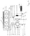
- Figure 1 shows a schematic representation of a first Embodiment of an internal combustion engine according to the invention.
- the internal combustion engine 1 is an internal combustion engine with reference number 1 designated.
- the internal combustion engine 1 is in the present exemplary embodiment as a four-cylinder internal combustion engine in Row construction and thus has four in series to each other arranged cylinder 2 on.
- the internal combustion engine 1 has a fresh air side 3 and an exhaust side 4, wherein the inlets 7 on the fresh air side 3 with a charge air manifold 5 and the outlets 8 of the internal combustion engine 1 connected on the exhaust side 4 with two exhaust manifolds 6 are.
- the internal combustion engine 1 is provided with a reference number 10 designated turbocharger charged.
- the turbocharger 10 is in the present exemplary embodiment formed in one stage and thus has a turbine 13 and a compressor 14, which a common shaft 15 are coupled together.
- the Exhaust manifold 6 is upstream with exhaust lines 20, 21 connected via which the exhaust gas from the cylinders 2 of the Internal combustion engine 1 can be derived.
- Charge air lines 23, 24 are provided, which are upstream are connected to the charge air manifold 5.
- the Cylinders 2 of the internal combustion engine 1 charge air can be supplied.
- a charge air cooler 26 is also provided, which is in the charge air line 24 between the compressor 14 and the inlets 7 the internal combustion engine 1 is arranged.
- a pipe 33 is provided, which is parallel to Compressor 14 is arranged switched. This pipe 33 thus branches out of the charge air line before the inlet of the compressor 14 23 and opens behind the compressor 14 in the Charge air line 24.
- a Bypass valve 34 arranged in the pipeline 33.
- the bypass valve 34 can for example controlled electrically, pneumatically or hydraulically or be regulated.
- the bypass device 40 is a bypass device 40 on the exhaust gas side intended.
- the bypass device 40 comprises a pipe section 41, which is connected in parallel to the turbine 13 is arranged.
- the pipe section 41 thus branches from the exhaust pipe 20 in front of the turbine wheel 13 and opens behind the turbine 13 back into the exhaust pipe 21.
- the bypass device 40 also contains a switching device 42, which at a branch point 43 in front of the turbine wheel 13 is arranged in the exhaust pipe 20.
- This switching device 42 could also be configured or alternatively also provided in the area of the junction 44 be, although this arrangement is not so advantageous is like the arrangement just described in front of the turbine 13.
- the switching device 42 can also be controlled or regulated be trained.
- the particular advantage of this switching device 42 is that both between one Position at which the exhaust gas is completely through the exhaust pipe 20 flows and a position at which the exhaust gas is complete flows over the pipe section 41, back and forth can be switched down.
- the switching device 42 can, depending on the desired functionality as a pipe switch, as a control valve, as a switch with shut-off switch, formed as a slide or the like his.
- a catalytic converter 30 is arranged in the exhaust gas line 21.
- By means of the bypass device 40 according to the invention results there is an improved opportunity for influence to improve the light-off behavior of the catalyst 30.
- By bypass the turbines 13 of the exhaust gas turbocharger functioning as a heat sink the total exhaust gas mass flow through the line 41 are passed directly to the catalyst 30. Thereby is a faster start of the catalyst 30 and thus an increased conversion rate in the first few seconds of the Emission test possible.
- the switching device 42 and / or the bypass valve 34 can via a regulating or control device, not shown in FIG. 1 be adjustable or controllable.
- turbocharged has Engine 1 according to FIG. 2 has a turbocharger 10 with variable turbine geometry (VTG).
- VFG variable turbine geometry
- the turbocharged has Internal combustion engine according to Figure 3 near the engine Pre-catalyst 31.
- This pre-catalyst 31 is in the Pipe section 41 of the bypass device 40 is arranged.
- close to the motor means that the motor the internal combustion engine 1 coming, very hot exhaust gas flow to Pre-catalyst 31 a shorter distance through the exhaust pipe 20 must flow through, as far as the main catalyst 30.
- this pre-catalyst 31 is very dimensioned much smaller than with the main catalyst 30 due to its smaller size and much faster, especially because of its proximity to the engine is warmed up as the main catalyst 30 reaches the conversion rate compared to an arrangement without a pre-catalyst 31 it was acceptable much earlier Conversion values, since this is the case with a warm catalytic converter Exhaust gas is cleaned better than with a cold one.
- the pre-catalyst 31 remains switched on until the main catalyst 30 reaches its operating temperature Has. Then the switching device 42 becomes digital or infinitely variable switched so that the entire exhaust gas flow or at least part of the exhaust gas flow via the exhaust line 20 and the turbine 13 can flow. In normal operation, i.e. at fully heated main catalyst 30, is the pre-catalyst 31 typically bridged or switched off.
- the pre-catalyst 31 can also be configured in the area of the exhaust pipe arranged in front of the branch point 43 20 or in an area of the exhaust pipe 21, between the mouth 44 and the main catalyst 30 is arranged to be provided. However, such an arrangement is of the pre-catalyst 31 less advantageous because here the possibility of switching off is no longer available.
- the arrangement according to FIG. 4 has a two-stage turbocharger 10.
- Such a two-stage turbocharger 10 has a high pressure stage 11 and a low pressure stage 12.
- the high pressure stage 11 exists from a high pressure turbine 13 and a high pressure compressor 14, which are rigidly coupled to one another via a common shaft 15 are.
- the low pressure stage 12 low-pressure turbine coupled to one another by a common shaft 18 16 and low pressure compressor 17.
- the high pressure stage 11 is connected upstream of the low-pressure stage 12 on the exhaust gas side.
- the turbine impeller diameter of the low pressure turbine 16 is larger than that of the high-pressure turbine in the present exemplary embodiment 13, the impeller diameter ratio between Low pressure and high pressure turbines typically, however not necessarily in the range 1.2 to 1.8.
- the compressor wheel of the high pressure compressor 14 a smaller diameter than the compressor wheel of the low pressure compressor 17.
- the two turbines 13, 16 are connected in series with one another arranged, the high pressure turbine 13 with the low pressure turbine 16 is connected via the exhaust line 22 and of the low-pressure turbines 16 in the flow direction of the exhaust gas is arranged upstream.
- the low pressure compressors 17 and the high pressure compressor 14 in series arranged to each other and with each other via a charge air line 25 connected, the low pressure compressor 17 in Flow direction of the charge air to the high pressure compressor 14 is arranged upstream.
- FIG. 5 shows a fifth, particularly preferred embodiment of an inventive two-stage supercharged internal combustion engine.
- the preferred Arrangement in Figure 5 consists essentially of a Combination of the different designs of the internal combustion engines 1 corresponding to Figures 1 to 4.
- the turbocharger 10 is here with a two-stage turbocharger variable turbine geometry. Parallel to the two Turbines 13, 16 of the turbocharger 10 is a pre-catalyst 31 switched. According to the invention, this arrangement has a bypass device 40 which has a pipe section 41 therein contained switching device 42 contains on.
- the high pressure turbine 13 or the low pressure turbine 16 of course also as so-called twin turbines can be trained.
- the low-pressure turbine 16 have a variable turbine geometry.
- Figure 5 also shows a control device 50.
- the control device 50 is with the switching device 42 and / or the bypass switch 34 and / or the turbine 13 with variable Turbine geometry via control not shown in FIG. or data lines connected.
- This Adjust the flow through the pipe section 41 or the turbine 13 is stepless and advantageous dynamically adjustable by the control device 50.
- At least one sensor device 52 is provided.
- the sensor device 52 is designed to measure the temperature b1 of the exhaust gas and / or the temperature b2 at least a catalyst 30, 31 and / or the speed b3 of the internal combustion engine 1 and / or the speed b4 at least one Turbine 13, 16 and / or the speed b5 of at least one compressor 14, 17 to be recorded.
- This detected measurement signals b1 - b5, hereinafter also referred to as operating parameters are then fed to the control device 50.
- the control device 50 uses this to generate the control or control signals a1 - a3.
- the electronic engine control 50 for example a CPU
- the bypass device is in a particularly advantageous embodiment 40 together with pipe section 41 and switching device 42 in the housing 51 of the turbocharger 10 co-integrated.
- the invention is also the pre-catalyst 31 in integrated with the housing 51.
- This object is in everyone Figures 1 to 5 shown in dashed lines.
- Design is provided in the housing 51 pre-catalytic converter 31 integrated because of the proximity to the engine a much faster warm-up of the pre-catalyst 31 and with it a high efficiency in a short time the catalytic converter reachable. Beyond that by integrating at least part of the pipe sections 41 in the housing 51 a much simpler Assembly possible, which makes this overall arrangement more attractive overall becomes.
- the low pressure stage a larger diameter than the high pressure stage of the corresponding turbine wheels.
- Control of the switch for the bypass line and the Turbine geometry described by the engine control was in each case Control of the switch for the bypass line and the Turbine geometry described by the engine control.
- some or all of these elements can be also control otherwise or by a specially provided Adapt the control device to the desired operating state.
- the setting can be electrical, pneumatic, hydraulic, done mechanically or the like.
- the invention is of course not limited to two-stage turbocharger limited, but leaves rather, also on one-level or three or Expand multi-stage turbochargers.
- the invention is not exclusive to diesel engines limited in four-cylinder in-line construction, but can be used on any internal combustion engine with any number of whatever arranged Extend cylinders.
Abstract
Description
Die Erfindung betrifft ein Aufladesystem für eine Brennkraftmaschine und eine Brennkraftmaschine mit einem solchen Aufladesystem.The invention relates to a supercharging system for an internal combustion engine and an internal combustion engine with such a supercharging system.
Ein solches Aufladesystem ist beispielsweise ein Abgasturbolader, der einstufig, zwei- oder mehrstufig ausgebildet sein kann. Eine jeweilige Stufe des Abgasturboladers besteht aus einem Verdichter, der ladeluftseitig dem Einlass des Motors vorgeschaltet ist und einer Turbine, die dem abgasseitigen Motorauslass nachgeschaltet ist. Turbine und Verdichter sind miteinander über eine gemeinsame Welle gekoppelt.Such a charging system is, for example, an exhaust gas turbocharger, the one-stage, two-stage or multi-stage can. A respective stage of the exhaust gas turbocharger consists of a compressor on the charge air side of the intake of the engine is upstream and a turbine that the exhaust side Motor outlet is connected downstream. Turbine and compressor are coupled with each other via a common shaft.
Bei einem einstufig ausgebildeten Abgasturbolader wird der Abgasstrom über die Turbine des Abgasturboladers zum Katalysator geleitet. Problematisch an einer derartigen Abgasführung ist, dass der nachgeschaltete Katalysator eine bestimmte Zeitdauer benötigt, bis er die vorbestimmte Betriebstemperatur erreicht hat. Bis die Betriebstemperatur des Katalysators erreicht wird, ist jedoch die Konvertierungsrate und damit auch der Wirkungsgrad des Katalysators relativ gering. Dieses Problem wirkt sich besonders stark aus, wenn die Abgasrohrleitung bis zum nachgeschalteten Katalysator besonders lang ist.In the case of a single-stage exhaust gas turbocharger, the Exhaust gas flow via the turbine of the exhaust gas turbocharger to the catalytic converter directed. The problem with such exhaust gas routing is that the downstream catalyst has a certain Time required until it reaches the predetermined operating temperature has reached. Until the operating temperature of the catalyst is achieved, however, is the conversion rate and thus the efficiency of the catalyst is also relatively low. This Problem is particularly severe when the exhaust pipe particularly long until the downstream catalyst is.
Moderne turboaufgeladene Brennkraftmaschinen können mit einer zweistufigen Aufladung ausgestattet sein. Ein zweistufiger Turbolader weist eine Niederdruckstufe sowie eine Hochdruckstufe, die jeweils einen Verdichter und eine Turbine aufweisen. Das Abgas gelangt hier über die Hochdruckturbine und der nachgeschaltet angeordneten Niederdruckturbine zum Katalysator. Eine Brennkraftmaschine mit einem solchen zweistufigen Aufladesystem ist beispielsweise in den deutschen Offenlegungsschriften DE 198 37 978 A1 und DE 195 14 572 A1 ausführlich beschrieben, so dass auf deren Aufbau und Funktionsweise nicht näher eingegangen wird.Modern turbocharged internal combustion engines can with one two-stage charging. A two-stage Turbocharger has a low pressure stage as well as a high pressure stage, which each have a compressor and a turbine. The exhaust gas passes through the high pressure turbine and the downstream low pressure turbine to the catalyst. An internal combustion engine with such a two-stage Charging system is for example in the German published documents DE 198 37 978 A1 and DE 195 14 572 A1 in detail described, so that on their structure and operation is not discussed in more detail.
Bei einem zweistufig ausgebildeten Turbolader ist das Problem der schnellen Aufheizung des Katalysators auf die Betriebstemperatur noch gravierender, da der heiße Abgasstrom beim Durchlaufen durch die beiden Stufen des Turboladers stärker abgekühlt wird, so dass der nachgeschaltete Katalysator deutlich langsamer auf die Betriebtemperatur aufgeheizt wird als bei einem einstufigen Turbolader. Die Konvertierungsrate des Katalysators ist während dieser Zeitdauer nicht ausreichend.The problem is with a two-stage turbocharger the rapid heating of the catalytic converter to the operating temperature even more serious, since the hot exhaust gas flow at Pass through the two stages of the turbocharger more strongly is cooled so that the downstream catalyst becomes clear is heated up to the operating temperature more slowly than with a single-stage turbocharger. The conversion rate of the Catalyst is not sufficient during this period.
Die deutsche Offenlegungsschrift DE 198 33 619 A1 beschreibt eine einstufig ausgebildete, turboaufgeladene Brennkraftmaschine, bei der die Zeit verkürzt werden soll, bis zu der der Hauptkatalysator seine Betriebstemperatur erreicht hat. Zu diesem Zweck ist in der DE 198 33 619 A1 eine Bypassleitung zur Überbrückung der Turbine des Turboladers vorgesehen. In diese Bypassleitung kann fakultativ auch ein Startkatalysator angeordnet sein. Das Abgas strömt hier entweder über die Bypassleitung oder über die Turbine, wobei die Umschaltung zwischen Bypassbetrieb und Normalbetrieb mittels eines Schiebers erfolgt.The German patent application DE 198 33 619 A1 describes a single-stage, turbocharged internal combustion engine, at which the time is to be shortened up to which the Main catalytic converter has reached its operating temperature. To for this purpose is a bypass line in DE 198 33 619 A1 provided to bypass the turbine of the turbocharger. In this bypass line can optionally also be a starting catalyst be arranged. The exhaust gas flows here either through the bypass line or via the turbine, switching between Bypass operation and normal operation using a slide he follows.
Problematisch an der in der DE 198 33 619 A1 beschriebenen Anordnung ist, dass lediglich eine "digitale" Umschaltung zwischen Bypassbetrieb und Normalbetrieb möglich ist, das heißt, der Abgasstrom fließt entweder über die Bypassleitung oder über die Turbine. Auch ist das separate Bereitstellen einer eigens vorgesehenen Bypassrohrleitung aufgrund des dafür erforderlichen zusätzlichen Montageschrittes relativ aufwendig und damit teuer. Schließlich besteht auch hier das Problem, dass die Rohrleitung bis zum Katalysator durch diese Maßnahme typischerweise sehr lang ist, was einerseits aufgrund der dafür erforderlichen Rohrleitung relativ kostenintensiv ist und wodurch andererseits den Abgasstrom vorzeitig abkühlt.Problematic with that described in DE 198 33 619 A1 The arrangement is that only a "digital" switchover between bypass operation and normal operation is possible means that the exhaust gas flow either flows through the bypass line or via the turbine. This is also the separate provision a specially designed bypass pipe due to the required additional assembly step is relatively complex and therefore expensive. After all, this also exists here Problem that the pipeline to the catalyst through this Measure is typically very long, which is due on the one hand the pipeline required for this is relatively expensive and on the other hand, the exhaust gas flow prematurely cools.
Ausgehend von diesem Stand der Technik liegt der vorliegenden Erfindung die Aufgabe zugrunde, eine konstruktiv verbesserte turboaufgeladene Brennkraftmaschine mit einem Katalysator bereitzustellen, bei der der Katalysator insbesondere in der Startphase einen verbesserten Wirkungsgrad aufweist.Based on this prior art, the present Invention based on the object, a constructively improved provide turbocharged internal combustion engine with a catalyst, in which the catalyst in particular in the Starting phase has an improved efficiency.
Erfindungsgemäß wird diese Aufgabe durch ein Aufladesystem mit den Merkmalen des Patentanspruchs 1 gelöst. Demgemäß ist ein Aufladesystem für eine Brennkraftmaschine vorgesehen,
- mit mindestens einer abgasseitig angeordneten Turbine und mit mindestens einem ladeluftseitig angeordneten Verdichter, die jeweils über eine gemeinsame Welle gekoppelt sind,
- mit mindestens einem ersten Katalysator, der abgasseitig der Turbine in Reihe nachgeschaltet vorgesehen ist,
- mit einer Vorrichtung zum schnellen Aufheizen des Katalysators bei niedrigen Temperaturen der Brennkraftmaschine,
- die eine parallel zu mindestens einer Turbine angeordnete Rohrleitung zur Überbrückung der jeweiligen Turbine aufweist und
- die eine Schaltvorrichtung aufweist, die abgasseitig der parallelen Anordnung aus Rohrleitung und Turbine in Reihe vorgeschaltet vorgesehen ist und über die einstellbar ist, welche Teilmenge des Abgases jeweils über die Turbine und welche Teilmenge jeweils über die Rohrleitung dem ersten Katalysator direkt zugeführt wird.
- with at least one turbine arranged on the exhaust gas side and with at least one compressor arranged on the charge air side, each of which is coupled via a common shaft,
- with at least one first catalytic converter which is provided in series downstream of the turbine,
- with a device for rapid heating of the catalytic converter at low temperatures of the internal combustion engine,
- which has a pipeline arranged parallel to at least one turbine for bridging the respective turbine and
- which has a switching device which is provided upstream of the parallel arrangement of pipeline and turbine in series and via which it is possible to set which partial quantity of the exhaust gas is fed directly to the first catalyst via the turbine and which partial quantity in each case via the pipeline.
Die Aufgabe wird ferner durch eine Brennkraftmaschine mit den Merkmalen des Patentanspruchs 15 gelöst. Demgemäß ist eine Brennkraftmaschine vorgesehen,
- mit einem Motorblock, der mindestens einen Zylinder aufweist, mit einem Ladelufteinlass und einem Abgasauslass,
- mit einem Aufladesystem, dessen Turbinen dem Abgasauslass nachgeschaltet angeordnet sind und dessen Verdichter dem Ladelufteinlass vorgeschaltet angeordnet sind.
- with an engine block that has at least one cylinder, with a charge air inlet and an exhaust gas outlet,
- with a charging system, the turbines of which are arranged downstream of the exhaust gas outlet and the compressors of which are arranged upstream of the charge air inlet.
Der vorliegenden Erfindung liegt die Idee zugrunde, eine Umschalteinrichtung vorzusehen, mittels der zumindest ein Teil des Abgases an der Turbine vorbeigeleitet wird, wobei die Turbine für diesen Fall verschlossen oder zumindest zum Teil verschlossen ist. Im Falle einer verschlossenen Turbine wird das Abgas an der Turbine vorbeigeleitet und direkt in den Katalysator eingeleitet und zwar solange, bis der Katalysator seine Betriebstemperatur erreicht hat. Dadurch bedingt verkürzt sich die Zeit bis zum Erreichen der Betriebstemperatur des Katalysators. Somit erhöht sich die Konvertierungsrate und damit auch der Wirkungsgrad des Katalysators.The present invention is based on the idea of a switching device to provide by means of at least part of the exhaust gas is directed past the turbine, the Turbine closed for this case or at least partially is closed. In the case of a locked turbine the exhaust gas is directed past the turbine and directly into the catalytic converter initiated and until the catalyst has reached its operating temperature. Due to this shortened the time until the operating temperature is reached of the catalyst. This increases the conversion rate and with it the efficiency of the catalyst.
Der Schaltmechanismus zum Verschließen der Turbine sowie mindestens eines Teils des die Turbine überbrückenden Rohrleitungsabschnitts ist erfindungsgemäß im Gehäuse der Turbine bzw. des Turboladers mitintegriert. Der Schaltmechanismus erfolgt hier pneumatisch, hydraulisch, mechanisch oder elektrisch gesteuert. Die Steuerung dieses Schaltmechanismus erfolgt durch eine Steuereinrichtung, die beispielsweise Bestandteil der Motorsteuerung sein kann oder die alternativ auch als separater Mikrocontroller oder Mikroprozessor ausgeführt sein kann:The switching mechanism for closing the turbine as well as at least a part of the pipeline section bridging the turbine is according to the invention in the housing of the turbine or the turbocharger. The switching mechanism takes place here pneumatic, hydraulic, mechanical or electrical controlled. This switching mechanism is controlled by a control device, for example part the engine control can be or alternatively also designed as a separate microcontroller or microprocessor can be:
Vorteilhafte Ausgestaltungen und Weiterbildungen der Erfindung sind den Unteransprüchen sowie der Beschreibung unter Bezugnahme auf die Zeichnung entnehmbar.Advantageous refinements and developments of the invention are the dependent claims and the description below Removable reference to the drawing.
Die Erfindung wird nachfolgend anhand der in den Figuren der Zeichnung angegebenen Ausführungsbeispiele näher erläutert. Es zeigt dabei:
- Figur 1
- ein erstes Ausführungsbeispiel einer erfindungsgemäßen, einstufig aufgeladenen Brennkraftmaschine mit einer Bypasseinrichtung;
Figur 2- ein zweites Ausführungsbeispiel einer erfindungsgemäßen, einstufig aufgeladenen Brennkraftmaschine entsprechend Figur 1 mit variabler Turbinengeometrie;
Figur 3- ein drittes Ausführungsbeispiel einer erfindungsgemäßen, einstufig aufgeladenen Brennkraftmaschine entsprechend Figur 1 mit Vorkatalysator in der Bypassleitung;
- Figur 4
- ein viertes Ausführungsbeispiel einer erfindungsgemäßen Brennkraftmaschine mit einem zweistufigen Turbolader;
Figur 5- ein fünftes, besonders bevorzugtes Ausführungsbeispiel einer erfindungsgemäßen, zweistufig aufgeladenen Brennkraftmaschine.
- Figure 1
- a first embodiment of an inventive single-stage supercharged engine with a bypass device;
- Figure 2
- a second embodiment of a single-stage supercharged internal combustion engine according to the invention corresponding to Figure 1 with variable turbine geometry;
- Figure 3
- a third embodiment of an inventive single-stage supercharged engine according to Figure 1 with pre-catalyst in the bypass line;
- Figure 4
- a fourth embodiment of an internal combustion engine according to the invention with a two-stage turbocharger;
- Figure 5
- a fifth, particularly preferred embodiment of an inventive, two-stage supercharged internal combustion engine.
In allen Figuren der Zeichnung sind gleiche bzw. funktionsgleiche Elemente - sofern nichts anderes angegeben ist - mit gleichen Bezugszeichen versehen worden. In allen Figuren der Zeichnung wurde-ferner die Richtungen des Abgasstromes sowie des Ladeluftstromes jeweils durch Pfeile in den entsprechenden Rohrleitungen bezeichnet.All figures in the drawing have the same or functionally the same Unless otherwise stated, elements with have been provided with the same reference numerals. In all figures of the Drawing was further-the directions of the exhaust gas flow as well of the charge air flow by arrows in the corresponding Pipelines called.
Figur 1 zeigt in einer schematischen Darstellung ein erstes Ausführungsbeispiel einer erfindungsgemäßen Brennkraftmaschine.Figure 1 shows a schematic representation of a first Embodiment of an internal combustion engine according to the invention.
In Figur 1 ist mit Bezugszeichen 1 eine Brennkraftmaschine
bezeichnet. Die Brennkraftmaschine 1 ist im vorliegenden Ausführungsbeispiel
als vierzylindrige Brennkraftmaschine in
Reihenbauweise ausgebildet und weist somit vier in Reihe zueinander
angeordnete Zylinder 2 auf. Die Brennkraftmaschine 1
weist eine Frischluftseite 3 und eine Abgasseite 4 auf, wobei
die Einlässe 7 auf der Frischluftseite 3 mit einer Ladeluftsammelleitung
5 und die Auslässe 8 der Brennkraftmaschine 1
auf der Abgasseite 4 mit zwei Abgassammelleitungen 6 verbunden
sind.1 is an internal combustion engine with reference number 1
designated. The internal combustion engine 1 is in the present exemplary embodiment
as a four-cylinder internal combustion engine in
Row construction and thus has four in series to each other
arranged
Die Brennkraftmaschine 1 wird über einen mit Bezugszeichen 10
bezeichneten Turbolader aufgeladen. Der Turbolader 10 ist im
vorliegenden Ausführungsbeispiel einstufig ausgebildet und
weist somit eine Turbine 13 und einen Verdichter 14, die über
eine gemeinsame Welle 15 miteinander gekoppelt sind, auf. Die
Abgassammelleitung 6 ist stromaufwärts mit Abgasleitungen 20,
21 verbunden, über die das Abgas aus den Zylindern 2 der
Brennkraftmaschine 1 abgeleitet werden kann. In gleicher Weise
sind Ladeluftleitungen 23, 24 vorgesehen, die stromaufwärts
mit der Ladeluftsammelleitung 5 verbunden sind. Über
die Ladeluftleitungen 23, 24 und den Verdichter 14 ist den
Zylindern 2 der Brennkraftmaschine 1 Ladeluft zuführbar.The internal combustion engine 1 is provided with a
Ferner ist ein Ladeluftkühler 26 vorgesehen, der in der Ladeluftleitung
24 zwischen dem Verdichter 14 und den Einlässen 7
der Brennkraftmaschine 1 angeordnet ist.A
Ferner ist eine Rohrleitung 33 vorgesehen, die parallel zum
Verdichter 14 geschaltet angeordnet ist. Diese Rohrleitung 33
zweigt somit vor dem Einlass des Verdichters 14 aus der Ladeluftleitung
23 ab und mündet hinter dem Verdichter 14 in die
Ladeluftleitung 24 ein. In der Rohrleitung 33 ist ferner ein
Bypassventil 34 angeordnet. Die Rohrleitung 33 mit dem darin
enthaltenen Bypassventil 34 bzw. dem Rohrschalter 34 überbrückt
somit den Verdichter 14. Das Bypassventil 34 kann beispielsweise
elektrisch, pneumatisch oder hydraulisch gesteuert
oder geregelt werden.Furthermore, a
Erfindungsgemäß ist eine abgasseitige Bypasseinrichtung 40
vorgesehen. Die Bypasseinrichtung 40 umfasst einen Rohrleitungsabschnitt
41, der parallel zu der Turbine 13 geschaltet
angeordnet ist. Der Rohrleitungsabschnitt 41 zweigt somit von
der Abgasleitung 20 vor dem Turbinenrad 13 ab und mündet hinter
der Turbine 13 wieder in die Abgasleitung 21 ein.According to the invention is a
Die Bypasseinrichtung 40 enthält ferner eine Umschalteinrichtung
42, die in einem Abzweigpunkt 43 vor dem Turbinenrad 13
in der Abgasleitung 20 angeordnet ist. In einer alternativen
Ausgestaltung könnte diese Umschalteinrichtung 42 zusätzlich
oder alternativ auch in dem Bereich der Einmündung 44 vorgesehen
sein, wenngleich diese Anordnung nicht so vorteilhaft
ist wie die eben beschriebene Anordnung vor der Turbine 13.
Die Umschalteinrichtung 42 kann ebenfalls steuerbar oder regelbar
ausgebildet sein. Der besondere Vorteil dieser Umschalteinrichtung
42 besteht darin, dass sowohl zwischen einer
Position, bei der das Abgas vollständig über die Abgasleitung
20 strömt und einer Position, bei der das Abgas vollständig
über den Rohrleitungsabschnitt 41 strömt, hin- und
hergeschaltet werden kann. Neben dieser quasi "digitalen" Umschaltmöglichkeit
besteht in einer sehr vorteilhaften Betriebsweise
auch die Möglichkeit, lediglich ein Teil des Abgases
über die Abgasleitung 20 strömen zu lassen, während der
restliche Teil des Abgases über den Rohrleitungsabschnitt 41
strömt. Damit ist gewissermaßen ein stufenloses Schalten des-Abgasstromes
möglich, wodurch stufenlos und damit gezielt eine
gewisse Abgasmenge über die beiden Rohrleitungen 20, 21,
41 verteilt werden kann. Damit ist mithin eine an den jeweiligen
Betriebszustand der Brennkraftmaschine 1 und des Turboladers
10 angepasste und optimierte Abgasverteilung in den
Abgasleitungen 20, 21, 41 einstellbar.The
Die Umschalteinrichtung 42 kann je nach gewünschter Funktionalität
als Rohrschalter, als Regelventil, als Weiche mit Absperrschalter,
als Schieber oder dergleichen ausgebildet
sein. In der Abgasleitung 21 ist ein Katalysator 30 angeordnet.
Mittels der erfindungsgemäßen Bypasseinrichtung 40 ergibt
sich eine verbesserte Einflussmöglichkeit zur Verbesserung
des Anspringverhaltens des Katalysators 30. Durch Umgehung
der als Wärmesenke fungierenden Turbinen 13 des Abgasturboladers
kann der gesamte Abgasmassenstrom über die Leitung
41 direkt zum Katalysator 30 geleitet werden. Dadurch
ist ein schnelleres Anspringen des Katalysators 30 und somit
eine erhöhte Konvertierungsrate in den ersten Sekunden des
Abgastestes möglich.The switching
Die Umschalteinrichtung 42 und/oder das Bypassventil 34 können
über eine in Figur 1 nicht dargestellte Regel- oder Steuereinrichtung
regelbar oder steuerbar ausgebildet sein.The switching
Im Unterschied zu der Anordnung in Figur 1 weist die turboaufgeladene
Kraftmaschine 1 gemäß Figur 2 einen Turbolader 10
mit variabler Turbinengeometrie (VTG) auf. Die Funktionalität
einer solchen variablen Turbinengeometrie ist in allen Figuren
mit einem Pfeil angedeutet.In contrast to the arrangement in Figure 1, the turbocharged has
Engine 1 according to FIG. 2 has a
Im Unterschied zu der Anordnung in Figur 1 weist die turboaufgeladene
Brennkraftmaschine gemäß Figur 3 einen motornahen
Vorkatalysator 31 auf. Dieser Vorkatalysator 31 ist in dem
Rohrleitungsabschnitt 41 der Bypasseinrichtung 40 angeordnet.
Motornah bedeutet in diesem Zusammenhang, dass der vom Motor
der Brennkraftmaschine 1 kommende, sehr heiße Abgasstrom zum
Vorkatalysator 31 eine geringere Wegstrecke durch die Abgasleitung
20 durchströmen muss, als bis zum Hauptkatalysator
30. Durch das Bereitstellen eines Vorkatalysators 31 wird eine
weitere Verbesserung bezüglich des Anspringverhaltens und
der Konvertierungsrate in den ersten Sekunden des Abgastests
erzielt. Typischerweise ist dieser Vorkatalysator 31 sehr
viel kleiner dimensioniert als der Hauptkatalysator 30 mit
der Folge, dass dieser aufgrund seiner geringeren Größe und
insbesondere aufgrund seiner Motornähe sehr viel schneller
aufgewärmt wird als der Hauptkatalysator 30. Dadurch bedingt
erreicht die Konvertierungsrate im Vergleich zu einer Anordnung
ohne Vorkatalysator 31 bereits sehr viel früher annehmbare
Konvertierungswerte, da bei einem warmen Katalysator das
Abgas besser gereinigt wird als bei einem kalten.In contrast to the arrangement in Figure 1, the turbocharged has
Internal combustion engine according to Figure 3 near the
Der Vorkatalysator 31 bleibt so lange zugeschaltet, bis auch
der Hauptkatalysator 30 seine Betriebstemperatur erreicht
hat. Dann wird die Umschalteinrichtung 42 digital oder stufenlos
umgeschaltet, so dass der gesamte Abgasstrom oder zumindest
ein Teil des Abgasstromes über die Abgasleitung 20
und die Turbine 13 strömen kann. Im Normalbetrieb, d.h. bei
voll aufgeheiztem Hauptkatalysator 30, ist der Vorkatalysator
31 typischerweise überbrückt bzw. weggeschaltet. In einer alternativen
Ausgestaltung kann der Vorkatalysator 31 auch in
dem vor dem Abzweigpunkt 43 angeordneten Bereich der Abgasleitung
20 oder auch in einem Bereich der Abgasleitung 21,
der zwischen der Einmündung 44 und dem Hauptkatalysator 30
angeordnet ist, vorgesehen sein. Jedoch ist eine solche Anordnung
des Vorkatalysators 31 weniger vorteilhaft, da hier
die Möglichkeit des Wegschaltens nicht mehr gegeben ist.The pre-catalyst 31 remains switched on until
the
Im Unterschied zu Figur 1 weist die Anordnung gemäß Figur 4
einen zweistufig ausgebildeten Turbolader 10 auf. Ein solcher
zweistufiger Turbolader 10 weist eine Hochdruckstufe 11 und
eine Niederdruckstufe 12 auf. Die Hochdruckstufe 11 besteht
aus einer Hochdruckturbine 13 und einem Hochdruckverdichter
14, die über eine gemeinsame Welle 15 miteinander starr gekoppelt
sind. In gleicher Weise weist die Niederdruckstufe 12
miteinander durch eine gemeinsame Welle 18 gekoppelte Niederdruckturbine
16 und Niederdruckverdichter 17 auf. Die Hochdruckstufe
11 ist der Niederdruckstufe 12 abgasseitig vorgeschaltet.In contrast to FIG. 1, the arrangement according to FIG. 4 has
a two-
Durch das Bereitstellen eines zweistufig ausgebildeten Turboladers
10 lässt sich eine Erhöhung des Drehmomentes und damit
einhergehend der Nennleistung der Brennkraftmaschine 1 erzielen. By providing a two-
Der Turbinenlaufraddurchmesser der Niederdruckturbine 16 ist
im vorliegenden Ausführungsbeispiel größer als der der Hochdruckturbine
13, wobei das Laufraddurchmesserverhältnis zwischen
Niederdruck- und Hochdruckturbine typischerweise, jedoch
nicht notwendigerweise, im Bereich 1,2 bis 1,8 liegt. In
gleicher Weise weist das Verdichterrad des Hochdruckverdichters
14 einen geringeren Durchmesser als das Verdichterrad
des Niederdruckverdichters 17 auf.The turbine impeller diameter of the
Die beiden Turbinen 13, 16 sind zueinander in Reihe geschaltet
angeordnet, wobei die Hochdruckturbine 13 mit der Niederdruckturbine
16 über die Abgasleitung 22 verbunden ist und
der Niederdruckturbinen 16 in Strömungsrichtung des Abgases
vorgeschaltet angeordnet ist. In gleicher Weise sind der Niederdruckverdichter
17 und der Hochdruckverdichter 14 in Reihe
zueinander angeordnet und über eine Ladeluftleitung 25 miteinander
verbunden, wobei der Niederdruckverdichter 17 in
Strömungsrichtung der Ladeluft dem Hochdruckverdichter 14
vorgeschaltet angeordnet ist.The two
Im Bedarfsfall kann zusätzlich zu dem Ladeluftkühler 26 ein
weiterer Ladeluftkühler vorgesehen sein, der beispielsweise
in der Ladeluftleitung 25 angeordnet ist.If necessary, in addition to the
Figur 5 zeigt in einer schematischen Darstellung ein fünftes,
besonders bevorzugtes Ausführungsbeispiel einer erfindungsgemäßen
zweistufig aufgeladenen Brennkraftmaschine. Die bevorzugte
Anordnung in Figur 5 besteht im wesentlichen aus einer
Kombination der unterschiedlichen Ausgestaltungen der Brennkraftmaschinen
1 entsprechend den Figuren 1 bis 4. Der Turbolader
10 ist hier als zweistufig ausgebildeter Turbolader mit
variabler Turbinengeometrie ausgebildet. Parallel zu den beiden
Turbinen 13, 16 des Turboladers 10 ist ein Vorkatalysator
31 geschaltet. Erfindungsgemäß weist diese Anordnung eine Bypasseinrichtung
40, die ein Rohrleitungsabschnitt 41 mit darin
enthaltener Umschalteinrichtung 42 enthält, auf. FIG. 5 shows a fifth,
particularly preferred embodiment of an inventive
two-stage supercharged internal combustion engine. The preferred
Arrangement in Figure 5 consists essentially of a
Combination of the different designs of the internal combustion engines
1 corresponding to Figures 1 to 4. The
An dieser Stelle sei anzumerken, dass in allen Ausführungsbeispielen
die Hochdruckturbine 13 oder auch die Niederdruckturbine
16 selbstverständlich auch als sogenannte Zwillingsstromturbinen
ausgebildet sein können. Darüber hinaus kann in
den Figuren 4 und 5 zusätzlich oder alternativ auch die Niederdruckturbine
16 eine variable Turbinengeometrie aufweisen.At this point it should be noted that in all exemplary embodiments
the
Figur 5 zeigt ferner eine Steuereinrichtung 50. Die Steuereinrichtung
50 ist mit der Umschalteinrichtung 42 und/oder
dem Bypassschalter 34 und/oder der Turbine 13 mit variabler
Turbinengeometrie über in Figur 5 nicht dargestellte Steuer-
bzw. Datenleitungen verbunden. Dadurch sind diese Elemente
des Turboladers 10 mit Steuer- bzw. Datensignalen a1, a2, a3
derart beaufschlagbar, dass diese bedarfsgemäß eingestellt
werden können. Insbesondere kann dadurch gewährleistet werden,
dass bei der Umschalteinrichtung 42 eine genau vorbestimmte
Abgasmenge jeweils durch die Turbine 13 strömt bzw.
über den Rohrleitungsabschnitt 41 abgezweigt wird. Dieses
Einstellen des Durchflusses durch den Rohrleitungsabschnitt
41 bzw. die Turbine 13 ist stufenlos und vorteilhafterweise
dynamisch durch die Steuereinrichtung 50 einstellbar. Gleiches
gilt selbstverständlich bei der Einstellung der jeweiligen
Position der VTG-Turbine 13 sowie des Bypassschalters 34.
Auf diese Weise ist es möglich, in Abhängigkeit von der jeweiligen
Motorleistung der augenblicklichen Motorbelastung
und des Abgasgesamtstromes eine optimale, d.h. möglichst
schnelle Aufwärmung der Katalysatoren 30, 31 zu erreichen.Figure 5 also shows a
Zusätzlich ist mindestens eine Sensoreinrichtung 52 vorgesehen.
Die Sensoreinrichtung 52 ist dazu ausgelegt, die Temperatur
b1 des Abgases und/oder die Temperatur b2 mindestens
eines Katalysators 30, 31 und/oder die Drehzahl b3 der Brennkraftmaschine
1 und/oder die Drehzahl b4 mindestens einer
Turbine 13, 16 und/oder der Drehzahl b5 mindestens eines Verdichters
14, 17 zu erfassen. Diese erfasste Messsignale b1 -
b5, die nachfolgend auch als Betriebskenngrößen bezeichnet
werden, werden anschließend der Steuereinrichtung 50 zugeführt.
Die Steuereinrichtung 50 erzeugt daraus die Regel-
bzw. Steuersignale a1 - a3.In addition, at least one
Zur Steuerung der Umschalteinrichtung, der Rohrschalter, der
Verschlusskörper sowie der in ihrer Geometrie variabel einstellbaren
Turbinen in Abhängigkeit von Betriebskenngrößen
sind diese an die elektronische Motorsteuerung 50, beispielsweise
eine CPU, angeschlossen, die für eine betriebsoptimale
Aufteilung des Abgasmassenstromes sorgt. Durch die mögliche
Einstellung unterschiedlicher Bypassraten, Durchflussraten
und Turbinenstellungen erhält man vorteilhafterweise einen
zusätzlichen Freiheitsgrad zur Aufteilung der gesamten Abgasmenge,
der im kalten Zustand einerseits einen effektiven Einsatz
des Turboladers und andererseits eine hohe Abgasreinigung
aufgrund der hohen Effizienz der Katalysatoren ermöglicht.To control the switching device, the pipe switch, the
Closure body as well as the variably adjustable in its geometry
Turbines depending on operating parameters
these are to the
In einer besonders vorteilhaften Ausgestaltung ist die Bypasseinrichtung
40 samt Rohrleitungsabschnitt 41 und Umschalteinrichtung
42 in dem Gehäuse 51 des Turboladers 10
mitintegriert. In einer besonders vorteilhaften Ausgestaltung
der Erfindung ist zusätzlich auch der Vorkatalysator 31 in
dem Gehäuse 51 mitintegriert. Dieser Gegenstand ist in allen
Figuren 1 bis 5 gestrichelt dargestellt. Durch diese erfindungsgemäße
Ausgestaltung ist bei Vorsehen eines im Gehäuse
51 mitintegrierten Vorkatalysators 31 aufgrund der Motornähe
eine sehr viel schnellere Aufwärmung des Vorkatalysators 31
und damit einhergehend bereits in kurzer Zeit eine hohe Effizienz
der Katalysatoranordnung erreichbar. Darüber hinaus ist
durch die Integration zumindest eines Teil des Rohrleitungsabschnitte
41 in das Gehäuse 51 eine sehr viel einfachere
Montage möglich, wodurch diese Gesamtanordnung insgesamt kostenattraktiver
wird.The bypass device is in a particularly
In den vorstehenden Ausführungsbeispielen weist die Niederdruckstufe einen gegenüber der Hochdruckstufe größeren Durchmesser der entsprechenden Turbinenräder auf. In the above embodiments, the low pressure stage a larger diameter than the high pressure stage of the corresponding turbine wheels.
In den vorstehenden Ausführungsbeispielen wurde jeweils eine Steuerung des Umschalters für die Bypassleitung sowie der Turbinengeometrie durch die Motorsteuerung beschrieben. Selbstverständlich lassen sich einige oder alle diese Elemente auch anderweitig steuern oder durch eine eigens vorgesehene Regeleinrichtung an den gewünschten Betriebszustand anpassen. Die Einstellung kann dabei elektrisch, pneumatisch, hydraulisch, mechanisch oder dergleichen erfolgen.In the above exemplary embodiments, one was in each case Control of the switch for the bypass line and the Turbine geometry described by the engine control. Of course, some or all of these elements can be also control otherwise or by a specially provided Adapt the control device to the desired operating state. The setting can be electrical, pneumatic, hydraulic, done mechanically or the like.
Die Erfindung sei selbstverständlich nicht ausschließlich auf zweistufig ausgebildete Turbolader beschränkt, sondern lässt sich vielmehr auch auf einstufig ausgebildete oder drei- oder mehrstufig ausgebildete Turbolader erweitern.The invention is of course not limited to two-stage turbocharger limited, but leaves rather, also on one-level or three or Expand multi-stage turbochargers.
Schließlich sei die Erfindung nicht ausschließlich auf Diesel-Brennkraftmaschinen in Vierzylinder-Reihenbauweise beschränkt, sondern lässt sich auf beliebige Brennkraftmaschinen mit einer beliebigen Anzahl von wie auch immer angeordneten Zylindern erweitern.After all, the invention is not exclusive to diesel engines limited in four-cylinder in-line construction, but can be used on any internal combustion engine with any number of whatever arranged Extend cylinders.
Zusammenfassend kann festgestellt werden, dass durch den wie beschrieben ausgestalteten Turbolader mit stufenloser Umschaltung zwischen Normalbetrieb und Bypassbetrieb, bei dem die Bypassleitung vorteilhafterweise im Gehäuse des Turboladers mitintegriert ist, auf einfache jedoch nichts desto trotz sehr effektive Weise ein höherer Wirkungsgrad des Katalysators erzielbar ist, ohne dass eine konstruktiv aufwendige, teure Lösung gemäß dem Stand der Technik vorgenommen werden muss.In summary, it can be stated that by how described turbocharger with stepless switching between normal operation and bypass operation, in which the bypass line advantageously in the housing of the turbocharger is integrated, in simple but nonetheless despite a very effective way, a higher efficiency of the catalyst can be achieved without a structurally complex, expensive solution can be made according to the prior art got to.
Die vorliegende Erfindung wurde anhand der vorstehenden Beschreibung so dargestellt, um das Prinzip der Erfindung und dessen praktische Anwendung bestmöglichst zu erklären, jedoch lässt sich die Erfindung bei geeigneter Abwandlung selbstverständlich in mannigfaltigen anderen Ausführungsformen realisieren. The present invention has been accomplished based on the foregoing description represented to the principle of the invention and to explain its practical application as best as possible, however the invention can be taken for granted with a suitable modification in various other embodiments realize.
- 11
- BrennkraftmaschineInternal combustion engine
- 22
- Zylindercylinder
- 33
- LadeluftseiteCharge air side
- 44
- Abgasseiteexhaust side
- 55
- LadeluftsammelleitungCharge-air manifold
- 66
- AbgassammelleitungExhaust manifold
- 77
- Einlässeinlets
- 88th
- Auslässeoutlets
- 1010
- Turboladerturbocharger
- 1111
- HochdruckstufeHigh pressure stage
- 1212
- NiederdruckstufeLow pressure stage
- 1313
- (Hochdruck-)Turbine(High pressure) turbine
- 1414
- (Hochdruck-)Verdichter(High pressure) compressor
- 1515
- Wellewave
- 1616
- NiederdruckturbineLow-pressure turbine
- 1717
- NiederdruckverdichterLow-pressure compressor
- 1818
- Wellewave
- 20, 21, 2220, 21, 22
- Abgasleitungenflues
- 23, 24, 2523, 24, 25
- LadeluftleitungenCharge air lines
- 2626
- LadeluftkühlerIntercooler
- 3030
- Katalysatorcatalyst
- 3131
- Vorkatalysatorprecatalyzer
- 3333
- Bypassleitungenbypass lines
- 3434
- Bypassventile, RohrschalterBypass valves, pipe switches
- 4040
- Bypasseinrichtungbypass device
- 4141
- RohrleitungsabschnittPipeline section
- 4242
- Umschalteinrichtungswitchover
- 4343
- Abzweigungdiversion
- 4444
- Einmündungjunction
- 5050
- Steuereinrichtungcontrol device
- 5151
- Gehäusecasing
- 5252
- Sensoreinrichtungsensor device
- a1 - a3a1 - a3
- Steuer-/DatensignaleControl / data signals
- b1 - b5b1 - b5
- Betriebskenngrößenoperating Data
Claims (17)
mit mindestens einer abgasseitig angeordneten Turbine (13, 16) und mit mindestens einem ladeluftseitig angeordneten Verdichter (14, 17), die jeweils über eine gemeinsame Welle (15, 18) gekoppelt sind,
mit mindestens einem ersten Katalysator (30), der abgasseitig der Turbine (13, 16) in Reihe nachgeschaltet vorgesehen ist,
mit einer Vorrichtung (40) zum schnellen Aufheizen des ersten Katalysators (30) bei niedrigen Temperaturen der Brennkraftmaschine (1),
die eine parallel zu mindestens einer Turbine (13, 16) angeordnete Rohrleitung (41) zur Überbrückung der jeweiligen Turbine (13, 16) aufweist und
die eine Schaltvorrichtung (42) aufweist, die abgasseitig der parallelen Anordnung aus Rohrleitung (41) und Turbine (13, 16) in Reihe vorgeschaltet vorgesehen ist und über die einstellbar ist, welche Teilmenge des Abgases jeweils über die Turbine (13, 16) und welche Teilmenge jeweils über die Rohrleitung (41) dem ersten Katalysator (30) direkt zugeführt wird.Supercharging system (10) for an internal combustion engine (1)
with at least one turbine (13, 16) arranged on the exhaust gas side and with at least one compressor (14, 17) arranged on the charge air side, each of which is coupled via a common shaft (15, 18),
with at least one first catalytic converter (30) which is provided in series downstream of the turbine (13, 16),
with a device (40) for quickly heating the first catalytic converter (30) at low temperatures of the internal combustion engine (1),
which has a pipeline (41) arranged parallel to at least one turbine (13, 16) for bridging the respective turbine (13, 16) and
which has a switching device (42) which is provided upstream of the parallel arrangement of pipeline (41) and turbine (13, 16) on the exhaust side and can be used to set the partial quantity of the exhaust gas via the turbine (13, 16) and which partial quantity is fed directly to the first catalyst (30) via the pipeline (41).
dadurch gekennzeichnet, dass die Vorrichtung (40) in einem Gehäuse (51) der Turbine (13, 16) und/oder des gesamten Aufladesystems (10) mitintegriert ist.Charging system according to claim 1,
characterized in that the device (40) is integrated in a housing (51) of the turbine (13, 16) and / or of the entire supercharging system (10).
dadurch gekennzeichnet, dass mindestens eine der Turbinen (13, 16) als Turbine mit variabler Turbinengeometrie ausgebildet ist.Charging system according to one of the preceding claims,
characterized in that at least one of the turbines (13, 16) is designed as a turbine with variable turbine geometry.
dadurch gekennzeichnet, dass ein zweiter Katalysator (31) vorgesehen ist, der in der Rohrleitung (41) angeordnet ist.Charging system according to one of the preceding claims,
characterized in that a second catalytic converter (31) is provided which is arranged in the pipeline (41).
dadurch gekennzeichnet, dass der zweite Katalysator (31) kleiner ausgebildet ist als der erste Katalysator (30) und dem ersten Katalysator (30) vorgeschaltet angeordnet ist.Charging system according to claim 4,
characterized in that the second catalyst (31) is made smaller than the first catalyst (30) and is arranged upstream of the first catalyst (30).
dadurch gekennzeichnet, dass der zweite Katalysator (31) in einem Gehäuse (51) der Turbine (13, 16) und/oder des gesamten Aufladesystems (10) mitintegriert ist.Charging system according to one of claims 4 or 5,
characterized in that the second catalytic converter (31) is also integrated in a housing (51) of the turbine (13, 16) and / or of the entire supercharging system (10).
dadurch gekennzeichnet, dass das Aufladesystem (10) als zweistufiger Turbolader (10) ausgebildet ist,
characterized in that the charging system (10) is designed as a two-stage turbocharger (10),
dadurch gekennzeichnet, dass eine Steuereinrichtung (50) zur Steuerung der Schaltvorrichtung (42) vorgesehen ist.Charging system according to one of the preceding claims,
characterized in that a control device (50) for controlling the switching device (42) is provided.
dadurch gekennzeichnet, dass mindestens eine Sensoreinrichtung (52) vorgesehen ist, welche zum Erfassen der Temperatur des Abgases und/oder der Temperatur mindestens eines Katalysators (30, 31) und/oder der Drehzahl der Brennkraftmaschine (1) und/oder der Drehzahl mindestens einer Turbine (13, 16) und/oder der Drehzahl mindestens eines Verdichters (14, 17) vorgesehen ist.Charging system according to one of the preceding claims,
characterized in that at least one sensor device (52) is provided which is used to detect the temperature of the exhaust gas and / or the temperature of at least one catalytic converter (30, 31) and / or the speed of the internal combustion engine (1) and / or the speed of at least one Turbine (13, 16) and / or the speed of at least one compressor (14, 17) is provided.
dadurch gekennzeichnet, dass die Schaltvorrichtung (42) steuerbar oder regelbar ausgebildet ist, wobei als Steuergröße bzw. Regelgröße (a1 - a3) ein von der Sensoreinrichtung (52) erfasstes oder davon abgeleitetes Signal vorgesehen ist.Charging system according to claim 9,
characterized in that the switching device (42) is designed to be controllable or regulatable, a signal detected by or derived from the sensor device (52) being provided as the control variable or control variable (a1-a3).
dadurch gekennzeichnet, dass die Steuergröße bzw. Regelgröße (a1 - a3) ein elektrisches, pneumatisches, mechanisches oder hydraulisches Signal ist.Charging system according to one of claims 9 or 10,
characterized in that the control variable or control variable (a1 - a3) is an electrical, pneumatic, mechanical or hydraulic signal.
dadurch gekennzeichnet, dass die Schaltvorrichtung (42) als Umschaltvorrichtung ausgebildet ist, die das Abgas der Brennkraftmaschine (1) entweder über mindestens eine Turbine (13, 16) oder über die Rohrleitung (41) leitet.Charging system according to one of the preceding claims,
characterized in that the switching device (42) is designed as a switching device which conducts the exhaust gas of the internal combustion engine (1) either via at least one turbine (13, 16) or via the pipeline (41).
dadurch gekennzeichnet, dass die Schaltvorrichtung (42) als Schieber und/oder als Klappe und/oder als Drosselventil und/oder als Rohrschalter ausgebildet. Charging system according to claim 12,
characterized in that the switching device (42) is designed as a slide and / or as a flap and / or as a throttle valve and / or as a pipe switch.
dadurch gekennzeichnet, dass die Steuereinrichtung (50) die Schaltvorrichtung (42) dynamisch in Abhängigkeit der Steuergröße und/oder der Regelgröße (a1 - a3) steuert.Charging system according to one of claims 8 to 13,
characterized in that the control device (50) controls the switching device (42) dynamically as a function of the control variable and / or the controlled variable (a1-a3).
mit einem Motorblock, der mindestens einen Zylinder (2) aufweist, mit mindestens einem Ladelufteinlass (5, 7) und mit mindestens einem Abgasauslass (6, 8),
mit einem Aufladesystem (10) nach einem der vorstehenden Ansprüche, dessen Turbinen (13, 16) dem Abgasauslass (6, 8) nachgeschaltet angeordnet sind und dessen Verdichter (14, 17) dem Ladelufteinlass (5, 7) vorgeschaltet angeordnet sind.Internal combustion engine (1)
with an engine block having at least one cylinder (2), with at least one charge air inlet (5, 7) and with at least one exhaust gas outlet (6, 8),
With a charging system (10) according to one of the preceding claims, the turbines (13, 16) of which are arranged downstream of the exhaust gas outlet (6, 8) and the compressors (14, 17) of which are arranged upstream of the charge air inlet (5, 7).
dadurch gekennzeichnet, dass das Aufladesystem (10) mindestens einen Turbolader (10) aufweist.Internal combustion engine according to claim 15,
characterized in that the charging system (10) has at least one turbocharger (10).
dadurch gekennzeichnet, dass die Brennkraftmaschine (1) als Otto-Motor oder als Diesel-Motor ausgebildet ist.Internal combustion engine according to one of claims 15 or 16,
characterized in that the internal combustion engine (1) is designed as a gasoline engine or as a diesel engine.
Priority Applications (2)
| Application Number | Priority Date | Filing Date | Title |
|---|---|---|---|
| EP02020006A EP1396619A1 (en) | 2002-09-05 | 2002-09-05 | Supercharging system for an internal combustion engine |
| JP2003288621A JP2004100694A (en) | 2002-09-05 | 2003-08-07 | Supercharger for internal-combustion engine and internal-combustion engine provided with such supercharger |
Applications Claiming Priority (1)
| Application Number | Priority Date | Filing Date | Title |
|---|---|---|---|
| EP02020006A EP1396619A1 (en) | 2002-09-05 | 2002-09-05 | Supercharging system for an internal combustion engine |
Publications (1)
| Publication Number | Publication Date |
|---|---|
| EP1396619A1 true EP1396619A1 (en) | 2004-03-10 |
Family
ID=31502734
Family Applications (1)
| Application Number | Title | Priority Date | Filing Date |
|---|---|---|---|
| EP02020006A Withdrawn EP1396619A1 (en) | 2002-09-05 | 2002-09-05 | Supercharging system for an internal combustion engine |
Country Status (2)
| Country | Link |
|---|---|
| EP (1) | EP1396619A1 (en) |
| JP (1) | JP2004100694A (en) |
Cited By (42)
| Publication number | Priority date | Publication date | Assignee | Title |
|---|---|---|---|---|
| DE102004031230A1 (en) * | 2004-06-29 | 2006-01-19 | Audi Ag | Load pressure control device for internal combustion engines with superchargers has mechanical rule member connected to electric motor and arranged in exhaust bypass line |
| EP1640598A1 (en) * | 2004-09-22 | 2006-03-29 | Ford Global Technologies, LLC, A subsidary of Ford Motor Company | Supercharged internal combustion engine and method for improving the emission behaviour of an internal combustion engine |
| EP1640596A1 (en) | 2004-09-22 | 2006-03-29 | Ford Global Technologies, LLC, A subsidary of Ford Motor Company | Supercharged internal combustion engine and method for operating such an internal combustion engine |
| EP1640597A1 (en) * | 2004-09-22 | 2006-03-29 | Ford Global Technologies, LLC, A subsidary of Ford Motor Company | Supercharged internal combustion engine and method for operating such an internal combustion engine |
| EP1669571A1 (en) * | 2004-12-08 | 2006-06-14 | Bayerische Motoren Werke Aktiengesellschaft | Combustion engine with an exhaust line |
| EP1672197A1 (en) * | 2004-12-14 | 2006-06-21 | Borgwarner, Inc. | Turbine flow regulating valve system |
| EP1679429A1 (en) * | 2004-12-14 | 2006-07-12 | BorgWarner Inc. | Turbine flow regulating valve system |
| EP1728989A1 (en) * | 2005-05-31 | 2006-12-06 | BorgWarner Inc. | Multistage turbocharger arrangement |
| DE102005043060A1 (en) * | 2005-09-07 | 2007-03-15 | Iav Gmbh Ingenieurgesellschaft Auto Und Verkehr | Turbocharger device for internal combustion engine, has controllable bypass line diverting upstream before one of turbines of one of exhaust gas turbochargers and again discharging in intersection downstream of turbine in exhaust gas line |
| WO2007036279A1 (en) * | 2005-09-29 | 2007-04-05 | Daimler Ag | Internal combustion engine having two exhaust gas turbochargers connected in series |
| WO2007096221A1 (en) * | 2006-02-22 | 2007-08-30 | Robert Bosch Gmbh | Method and apparatus for increasing the exhaust gas temperature of an internal combustion engine |
| US7426831B2 (en) | 2005-10-06 | 2008-09-23 | Borgwarner Inc. | Turbo charging system |
| FR2926593A3 (en) * | 2008-01-17 | 2009-07-24 | Renault Sas | Internal combustion engine i.e. oil engine, for motor vehicle, has by-pass duct that is parallel to exhaust duct, independent from turbines, and selectively circulates all or part of exhaust gas directly from manifold to depollution device |
| CN101925725A (en) * | 2008-02-29 | 2010-12-22 | 博格华纳公司 | Multi-stage turbocharging system with thermal bypass |
| DE102009041008A1 (en) * | 2009-09-10 | 2011-03-24 | Bayerische Motoren Werke Aktiengesellschaft | Turbine housing for turbo-charger, has turbine chamber with a circular cylindrical cross-section for supporting turbine wheel rotated around axis of turbine chamber |
| DE102009049993A1 (en) * | 2009-10-20 | 2011-04-21 | Continental Automotive Gmbh | Turbine for an exhaust gas turbocharger, exhaust gas turbocharger, motor vehicle and method for operating an exhaust gas turbocharger |
| DE102010043327A1 (en) * | 2010-11-03 | 2012-05-03 | Bosch Mahle Turbo Systems Gmbh & Co. Kg | Internal combustion engine for motor car, has switchable bypass arranged parallel to wastegate bypass in turbine housing, and additive catalytic converter arranged in switchable bypass, where wastegate bypass controls wastegate valve |
| CN1811145B (en) * | 2004-12-14 | 2012-08-01 | 博格华纳公司 | Turbine flow regulating valve system |
| EP2385231A3 (en) * | 2010-05-04 | 2013-01-23 | Alpraaz AB | Exhaust system for a combustion engine |
| WO2013010924A1 (en) * | 2011-07-19 | 2013-01-24 | Jaguar Cars Limited | Improvements in controlling i.c. engine emissions |
| CN102046940B (en) * | 2008-05-30 | 2013-05-22 | 株式会社Ihi | Method and system for warming up exhaust gas purifying catalyst |
| CN103225552A (en) * | 2013-04-08 | 2013-07-31 | 天津大学 | Power turbine series-parallel combined device and control system |
| DE202013103564U1 (en) | 2013-08-07 | 2013-09-05 | Ford Global Technologies, Llc | Charged internal combustion engine with exhaust aftertreatment |
| DE102012020828A1 (en) * | 2012-09-07 | 2014-03-13 | Technische Universität Dresden | Internal combustion engine i.e. 4-cylinder in-line diesel engine for passenger car, has control valve arranged between exhaust lines, and performing control of exhaust gas volumetric flow, which is conductible through each exhaust line |
| DE102013215574A1 (en) | 2013-08-07 | 2015-02-12 | Ford Global Technologies, Llc | Charged internal combustion engine with exhaust aftertreatment and method for operating such an internal combustion engine |
| DE202015101894U1 (en) | 2015-04-02 | 2015-05-06 | Ford Global Technologies, Llc | Two-stage rechargeable internal combustion engine with exhaust aftertreatment |
| DE202015102241U1 (en) | 2015-04-24 | 2015-06-01 | Ford Global Technologies, Llc | Two-stage rechargeable internal combustion engine with exhaust aftertreatment |
| DE202016103676U1 (en) | 2016-07-05 | 2016-07-26 | Ford Global Technologies, Llc | Two-stage rechargeable internal combustion engine with exhaust aftertreatment |
| CN103392058B (en) * | 2011-03-04 | 2016-09-21 | 博格华纳公司 | Multistep turbocharger arrangement |
| DE102015206043A1 (en) | 2015-04-02 | 2016-10-06 | Ford Global Technologies, Llc | Two-stage rechargeable internal combustion engine with exhaust aftertreatment and method for operating such an internal combustion engine |
| DE102015207547A1 (en) | 2015-04-24 | 2016-10-27 | Ford Global Technologies, Llc | Two-stage rechargeable internal combustion engine with exhaust aftertreatment and method for operating such an internal combustion engine |
| DE102015207545A1 (en) | 2015-04-24 | 2016-10-27 | Ford Global Technologies, Llc | Two-stage rechargeable internal combustion engine with exhaust aftertreatment and method for operating such an internal combustion engine |
| DE102004028482B4 (en) * | 2004-06-11 | 2018-01-04 | Volkswagen Ag | Internal combustion engine |
| DE102016212249A1 (en) | 2016-07-05 | 2018-01-11 | Ford Global Technologies, Llc | Two-stage direct injection internal combustion engine with exhaust aftertreatment and method of operating such an internal combustion engine |
| DE102016212251A1 (en) | 2016-07-05 | 2018-01-11 | Ford Global Technologies, Llc | Two-stage rechargeable internal combustion engine with exhaust aftertreatment and method for operating such an internal combustion engine |
| US9903268B2 (en) | 2015-04-02 | 2018-02-27 | Ford Global Technologies, Llc | Internal combustion engine with two-stage supercharging capability and with exhaust-gas aftertreatment arrangement, and method for operating an internal combustion engine |
| CN108019261A (en) * | 2016-10-28 | 2018-05-11 | 丰田自动车株式会社 | The pre-heating system of exhaust apparatus |
| US20180171903A1 (en) * | 2015-06-23 | 2018-06-21 | Volvo Truck Corporation | An internal combustion engine system |
| DE102018218406A1 (en) | 2018-10-26 | 2020-04-30 | BMTS Technology GmbH & Co. KG | Method for operating an internal combustion engine system |
| DE102019212774A1 (en) * | 2019-08-26 | 2021-03-04 | Ford Global Technologies, Llc | Two-stage chargeable internal combustion engine with exhaust gas aftertreatment and method for operating such an internal combustion engine |
| DE102020103865A1 (en) | 2020-02-14 | 2021-08-19 | Bayerische Motoren Werke Aktiengesellschaft | Internal combustion engine with an exhaust system |
| DE102020114125A1 (en) | 2020-05-27 | 2021-12-02 | Bayerische Motoren Werke Aktiengesellschaft | Internal combustion engine with an exhaust system |
Families Citing this family (9)
| Publication number | Priority date | Publication date | Assignee | Title |
|---|---|---|---|---|
| US7150151B2 (en) * | 2002-11-19 | 2006-12-19 | Cummins Inc. | Method of controlling the exhaust gas temperature for after-treatment systems on a diesel engine using a variable geometry turbine |
| JP2011021612A (en) * | 2004-05-06 | 2011-02-03 | Cummins Inc | Method of determining exhaust gas temperature for after-treatment system on internal combustion engine using variable geometry turbine |
| EP1640583A3 (en) * | 2004-09-27 | 2007-05-23 | BorgWarner Inc. | Multi-stage turbocharging system utilizing VTG turbine stage(s) |
| DE102004054449A1 (en) * | 2004-11-11 | 2006-05-18 | Daimlerchrysler Ag | Method for operating a supercharged internal combustion engine |
| JP4811366B2 (en) * | 2007-07-20 | 2011-11-09 | トヨタ自動車株式会社 | Exhaust control device for internal combustion engine |
| JP5130933B2 (en) * | 2008-02-07 | 2013-01-30 | マツダ株式会社 | Engine supercharger |
| JP5316763B2 (en) * | 2008-11-04 | 2013-10-16 | 株式会社Ihi | Gas shunting device for turbocharger |
| CN102232141B (en) * | 2010-02-26 | 2013-07-24 | 丰田自动车株式会社 | Internal combustion engine control device |
| CN103615309A (en) * | 2013-12-10 | 2014-03-05 | 吉林大学 | All-work-condition adjustable two-stage pressurizing system of internal combustion engine |
Citations (8)
| Publication number | Priority date | Publication date | Assignee | Title |
|---|---|---|---|---|
| JPH03275959A (en) * | 1990-03-26 | 1991-12-06 | Toyota Motor Corp | Emission control device of supercharged lean-burn gasoline internal combustion engine |
| US5195323A (en) * | 1991-07-31 | 1993-03-23 | Lorts Anthony R | Turbocharger-exhaust purifier wastegate |
| DE19514572A1 (en) | 1995-04-20 | 1996-10-24 | Man Nutzfahrzeuge Ag | Charged combustion engine with high pressure stage |
| JPH09125941A (en) * | 1995-10-30 | 1997-05-13 | Nissan Motor Co Ltd | Exhaust emission control device for engine |
| DE19837978A1 (en) | 1998-04-16 | 1999-11-04 | 3K Warner Turbosystems Gmbh | Air-flow controller in twin stage turbocharged internal combustion engine |
| DE19833619A1 (en) | 1998-07-25 | 2000-01-27 | Porsche Ag | Exhaust gas system for supercharged internal combustion engines, with bypass line divided downstream of branch from exhaust gas line into two guide paths |
| DE10015291A1 (en) * | 2000-03-28 | 2001-10-04 | Daimler Chrysler Ag | Turbocharged V-engine has two different sizes of turbocharger with series operation at low engine speeds and parallel operation at high engine speeds |
| EP1152133A2 (en) * | 2000-05-03 | 2001-11-07 | Audi Ag | Exhaust gas purifying apparatus |
-
2002
- 2002-09-05 EP EP02020006A patent/EP1396619A1/en not_active Withdrawn
-
2003
- 2003-08-07 JP JP2003288621A patent/JP2004100694A/en active Pending
Patent Citations (8)
| Publication number | Priority date | Publication date | Assignee | Title |
|---|---|---|---|---|
| JPH03275959A (en) * | 1990-03-26 | 1991-12-06 | Toyota Motor Corp | Emission control device of supercharged lean-burn gasoline internal combustion engine |
| US5195323A (en) * | 1991-07-31 | 1993-03-23 | Lorts Anthony R | Turbocharger-exhaust purifier wastegate |
| DE19514572A1 (en) | 1995-04-20 | 1996-10-24 | Man Nutzfahrzeuge Ag | Charged combustion engine with high pressure stage |
| JPH09125941A (en) * | 1995-10-30 | 1997-05-13 | Nissan Motor Co Ltd | Exhaust emission control device for engine |
| DE19837978A1 (en) | 1998-04-16 | 1999-11-04 | 3K Warner Turbosystems Gmbh | Air-flow controller in twin stage turbocharged internal combustion engine |
| DE19833619A1 (en) | 1998-07-25 | 2000-01-27 | Porsche Ag | Exhaust gas system for supercharged internal combustion engines, with bypass line divided downstream of branch from exhaust gas line into two guide paths |
| DE10015291A1 (en) * | 2000-03-28 | 2001-10-04 | Daimler Chrysler Ag | Turbocharged V-engine has two different sizes of turbocharger with series operation at low engine speeds and parallel operation at high engine speeds |
| EP1152133A2 (en) * | 2000-05-03 | 2001-11-07 | Audi Ag | Exhaust gas purifying apparatus |
Non-Patent Citations (2)
| Title |
|---|
| PATENT ABSTRACTS OF JAPAN vol. 016, no. 099 (M - 1220) 11 March 1992 (1992-03-11) * |
| PATENT ABSTRACTS OF JAPAN vol. 1997, no. 09 30 September 1997 (1997-09-30) * |
Cited By (58)
| Publication number | Priority date | Publication date | Assignee | Title |
|---|---|---|---|---|
| DE102004028482B4 (en) * | 2004-06-11 | 2018-01-04 | Volkswagen Ag | Internal combustion engine |
| DE102004031230A1 (en) * | 2004-06-29 | 2006-01-19 | Audi Ag | Load pressure control device for internal combustion engines with superchargers has mechanical rule member connected to electric motor and arranged in exhaust bypass line |
| EP1640598A1 (en) * | 2004-09-22 | 2006-03-29 | Ford Global Technologies, LLC, A subsidary of Ford Motor Company | Supercharged internal combustion engine and method for improving the emission behaviour of an internal combustion engine |
| EP1640596A1 (en) | 2004-09-22 | 2006-03-29 | Ford Global Technologies, LLC, A subsidary of Ford Motor Company | Supercharged internal combustion engine and method for operating such an internal combustion engine |
| EP1640597A1 (en) * | 2004-09-22 | 2006-03-29 | Ford Global Technologies, LLC, A subsidary of Ford Motor Company | Supercharged internal combustion engine and method for operating such an internal combustion engine |
| EP1669571A1 (en) * | 2004-12-08 | 2006-06-14 | Bayerische Motoren Werke Aktiengesellschaft | Combustion engine with an exhaust line |
| DE102004058955A1 (en) * | 2004-12-08 | 2006-06-29 | Bayerische Motoren Werke Ag | Internal combustion engine with an exhaust system |
| EP1672197A1 (en) * | 2004-12-14 | 2006-06-21 | Borgwarner, Inc. | Turbine flow regulating valve system |
| EP1679429A1 (en) * | 2004-12-14 | 2006-07-12 | BorgWarner Inc. | Turbine flow regulating valve system |
| US8490395B2 (en) | 2004-12-14 | 2013-07-23 | Borgwarner Inc. | Turbine regulating valve system |
| CN1811145B (en) * | 2004-12-14 | 2012-08-01 | 博格华纳公司 | Turbine flow regulating valve system |
| EP1728989A1 (en) * | 2005-05-31 | 2006-12-06 | BorgWarner Inc. | Multistage turbocharger arrangement |
| DE102005043060A1 (en) * | 2005-09-07 | 2007-03-15 | Iav Gmbh Ingenieurgesellschaft Auto Und Verkehr | Turbocharger device for internal combustion engine, has controllable bypass line diverting upstream before one of turbines of one of exhaust gas turbochargers and again discharging in intersection downstream of turbine in exhaust gas line |
| DE102005043060B4 (en) * | 2005-09-07 | 2012-10-04 | Iav Gmbh Ingenieurgesellschaft Auto Und Verkehr | Turbocharger device for an internal combustion engine |
| WO2007036279A1 (en) * | 2005-09-29 | 2007-04-05 | Daimler Ag | Internal combustion engine having two exhaust gas turbochargers connected in series |
| US8209982B2 (en) | 2005-09-29 | 2012-07-03 | Daimler Ag | Internal combustion engine having two exhaust gas turbochargers connected in series |
| US7426831B2 (en) | 2005-10-06 | 2008-09-23 | Borgwarner Inc. | Turbo charging system |
| WO2007096221A1 (en) * | 2006-02-22 | 2007-08-30 | Robert Bosch Gmbh | Method and apparatus for increasing the exhaust gas temperature of an internal combustion engine |
| FR2926593A3 (en) * | 2008-01-17 | 2009-07-24 | Renault Sas | Internal combustion engine i.e. oil engine, for motor vehicle, has by-pass duct that is parallel to exhaust duct, independent from turbines, and selectively circulates all or part of exhaust gas directly from manifold to depollution device |
| CN101925725A (en) * | 2008-02-29 | 2010-12-22 | 博格华纳公司 | Multi-stage turbocharging system with thermal bypass |
| CN102046940B (en) * | 2008-05-30 | 2013-05-22 | 株式会社Ihi | Method and system for warming up exhaust gas purifying catalyst |
| DE102009041008B4 (en) | 2009-09-10 | 2022-10-27 | Bayerische Motoren Werke Aktiengesellschaft | Exhaust gas turbocharger with integrated bypass flap and method for controlling the bypass flap |
| DE102009041008A1 (en) * | 2009-09-10 | 2011-03-24 | Bayerische Motoren Werke Aktiengesellschaft | Turbine housing for turbo-charger, has turbine chamber with a circular cylindrical cross-section for supporting turbine wheel rotated around axis of turbine chamber |
| DE102009049993A1 (en) * | 2009-10-20 | 2011-04-21 | Continental Automotive Gmbh | Turbine for an exhaust gas turbocharger, exhaust gas turbocharger, motor vehicle and method for operating an exhaust gas turbocharger |
| US8991174B2 (en) | 2009-10-20 | 2015-03-31 | Continental Automotive Gmbh | Turbine for an exhaust turbocharger, exhaust turbocharger, motor vehicle and method for operating an exhaust turbocharger |
| EP2385231A3 (en) * | 2010-05-04 | 2013-01-23 | Alpraaz AB | Exhaust system for a combustion engine |
| DE102010043327A8 (en) * | 2010-11-03 | 2012-08-16 | Bosch Mahle Turbo Systems Gmbh & Co. Kg | Internal combustion engine, turbine, exhaust gas turbocharger |
| DE102010043327A1 (en) * | 2010-11-03 | 2012-05-03 | Bosch Mahle Turbo Systems Gmbh & Co. Kg | Internal combustion engine for motor car, has switchable bypass arranged parallel to wastegate bypass in turbine housing, and additive catalytic converter arranged in switchable bypass, where wastegate bypass controls wastegate valve |
| CN103392058B (en) * | 2011-03-04 | 2016-09-21 | 博格华纳公司 | Multistep turbocharger arrangement |
| WO2013010924A1 (en) * | 2011-07-19 | 2013-01-24 | Jaguar Cars Limited | Improvements in controlling i.c. engine emissions |
| DE102012020828A1 (en) * | 2012-09-07 | 2014-03-13 | Technische Universität Dresden | Internal combustion engine i.e. 4-cylinder in-line diesel engine for passenger car, has control valve arranged between exhaust lines, and performing control of exhaust gas volumetric flow, which is conductible through each exhaust line |
| DE102012020828B4 (en) | 2012-09-07 | 2019-01-03 | Technische Universität Dresden | Internal combustion engine with two-stage supercharging and an integrated oxidation catalytic converter |
| CN103225552A (en) * | 2013-04-08 | 2013-07-31 | 天津大学 | Power turbine series-parallel combined device and control system |
| DE202013103564U1 (en) | 2013-08-07 | 2013-09-05 | Ford Global Technologies, Llc | Charged internal combustion engine with exhaust aftertreatment |
| DE102013215574A1 (en) | 2013-08-07 | 2015-02-12 | Ford Global Technologies, Llc | Charged internal combustion engine with exhaust aftertreatment and method for operating such an internal combustion engine |
| DE102015206043A1 (en) | 2015-04-02 | 2016-10-06 | Ford Global Technologies, Llc | Two-stage rechargeable internal combustion engine with exhaust aftertreatment and method for operating such an internal combustion engine |
| DE202015101894U1 (en) | 2015-04-02 | 2015-05-06 | Ford Global Technologies, Llc | Two-stage rechargeable internal combustion engine with exhaust aftertreatment |
| US9903268B2 (en) | 2015-04-02 | 2018-02-27 | Ford Global Technologies, Llc | Internal combustion engine with two-stage supercharging capability and with exhaust-gas aftertreatment arrangement, and method for operating an internal combustion engine |
| DE102015207547A1 (en) | 2015-04-24 | 2016-10-27 | Ford Global Technologies, Llc | Two-stage rechargeable internal combustion engine with exhaust aftertreatment and method for operating such an internal combustion engine |
| DE102015207545A1 (en) | 2015-04-24 | 2016-10-27 | Ford Global Technologies, Llc | Two-stage rechargeable internal combustion engine with exhaust aftertreatment and method for operating such an internal combustion engine |
| DE202015102241U1 (en) | 2015-04-24 | 2015-06-01 | Ford Global Technologies, Llc | Two-stage rechargeable internal combustion engine with exhaust aftertreatment |
| US20180171903A1 (en) * | 2015-06-23 | 2018-06-21 | Volvo Truck Corporation | An internal combustion engine system |
| US11022055B2 (en) * | 2015-06-23 | 2021-06-01 | Volvo Truck Corporation | Internal combustion engine system for exhaust gas recovery |
| DE102016212251A1 (en) | 2016-07-05 | 2018-01-11 | Ford Global Technologies, Llc | Two-stage rechargeable internal combustion engine with exhaust aftertreatment and method for operating such an internal combustion engine |
| DE102016212249A1 (en) | 2016-07-05 | 2018-01-11 | Ford Global Technologies, Llc | Two-stage direct injection internal combustion engine with exhaust aftertreatment and method of operating such an internal combustion engine |
| CN107575299A (en) * | 2016-07-05 | 2018-01-12 | 福特环球技术公司 | method and system for two-stage turbocharger |
| US10815873B2 (en) | 2016-07-05 | 2020-10-27 | Ford Global Technologies, Llc | Methods and systems for a two-stage turbocharger |
| DE202016103676U1 (en) | 2016-07-05 | 2016-07-26 | Ford Global Technologies, Llc | Two-stage rechargeable internal combustion engine with exhaust aftertreatment |
| CN107575299B (en) * | 2016-07-05 | 2021-07-09 | 福特环球技术公司 | Method and system for a two-stage turbocharger |
| DE102016212249B4 (en) | 2016-07-05 | 2024-05-02 | Ford Global Technologies, Llc | Two-stage turbocharged direct-injection internal combustion engine with exhaust aftertreatment and method for operating such an internal combustion engine |
| CN108019261A (en) * | 2016-10-28 | 2018-05-11 | 丰田自动车株式会社 | The pre-heating system of exhaust apparatus |
| EP3333391A3 (en) * | 2016-10-28 | 2018-06-20 | Toyota Jidosha Kabushiki Kaisha | Warm-up system for exhaust gas apparatus |
| DE102018218406A1 (en) | 2018-10-26 | 2020-04-30 | BMTS Technology GmbH & Co. KG | Method for operating an internal combustion engine system |
| EP3650677A1 (en) | 2018-10-26 | 2020-05-13 | BMTS Technology GmbH & Co. KG | Method for operating an internal combustion engine system |
| US11111844B2 (en) | 2018-10-26 | 2021-09-07 | BMTS Technology GmbH & Co. KG | Method for operating a combustion engine system |
| DE102019212774A1 (en) * | 2019-08-26 | 2021-03-04 | Ford Global Technologies, Llc | Two-stage chargeable internal combustion engine with exhaust gas aftertreatment and method for operating such an internal combustion engine |
| DE102020103865A1 (en) | 2020-02-14 | 2021-08-19 | Bayerische Motoren Werke Aktiengesellschaft | Internal combustion engine with an exhaust system |
| DE102020114125A1 (en) | 2020-05-27 | 2021-12-02 | Bayerische Motoren Werke Aktiengesellschaft | Internal combustion engine with an exhaust system |
Also Published As
| Publication number | Publication date |
|---|---|
| JP2004100694A (en) | 2004-04-02 |
Similar Documents
| Publication | Publication Date | Title |
|---|---|---|
| EP1396619A1 (en) | Supercharging system for an internal combustion engine | |
| EP1763627B1 (en) | Internal combustion engine featuring exhaust gas aftertreatment, and method for the operation thereof | |
| EP1375868B1 (en) | Engine brake apparatus for a turbocharged IC engine | |
| DE102009006359B4 (en) | Device and method for variable exhaust gas turbocharging and exhaust gas recirculation | |
| EP1275832B1 (en) | Multiple step super charging apparatus for an internal combustion engine | |
| EP1640598A1 (en) | Supercharged internal combustion engine and method for improving the emission behaviour of an internal combustion engine | |
| EP2134943A1 (en) | Turbocharged internal combustion engine and method | |
| DE102016212249B4 (en) | Two-stage turbocharged direct-injection internal combustion engine with exhaust aftertreatment and method for operating such an internal combustion engine | |
| DE102004028482B4 (en) | Internal combustion engine | |
| WO2011110314A1 (en) | Internal combustion engine having two-stage supercharging | |
| DE102005043060B4 (en) | Turbocharger device for an internal combustion engine | |
| DE102007028522A1 (en) | Method for operating turbocharged internal combustion engine, involves discharging exhaust gas mass flow, where two exhaust pipes are provided, and two exhaust gas turbo chargers are connected parallel to one another | |
| DE102015114450A1 (en) | Inlet-outlet device for an internal combustion engine | |
| DE4331943C3 (en) | Charging system for air-compressing internal combustion engines | |
| DE102008029197A1 (en) | Device for selective cylinder cutoff in rechargeable combustion engine, has two cylinders which are shiftable and detachable and high pressure stage is provided which consists of compressor and turbine | |
| WO2004111406A2 (en) | Internal combustion engine with exhaust gas recycling device and corresponding method | |
| DE19849495C2 (en) | Supercharged internal combustion engine with a bypass line bridging the exhaust gas turbine | |
| DE102009047929A1 (en) | Boost-pressure control method for two-stage exhaust-gas turbocharger of six-cylinder internal combustion engine, involves controlling or regulating high-pressure turbocharger in time-delayed manner according to boost-pressure control | |
| DE102015203157B4 (en) | Internal combustion engine with inside lying in the exhaust tract insulating metal structure | |
| WO2006032402A1 (en) | Internal combustion engine comprising an exhaust gas turbocharger, and associated method | |
| DE102016015357A1 (en) | Throttle device for an exhaust tract of an internal combustion engine | |
| DE102012101767B4 (en) | Internal combustion engine | |
| DE102008059657A1 (en) | Double-flow exhaust gas recirculation valve device for exhaust gas system of direct injecting engine of motor vehicle, has valves separately regulatable from each other to open and/or close openings, such that exhaust gas amount is adjusted | |
| DE202015101104U1 (en) | Insulating metal structure in an exhaust tract with two turbochargers | |
| DE202015102241U1 (en) | Two-stage rechargeable internal combustion engine with exhaust aftertreatment |
Legal Events
| Date | Code | Title | Description |
|---|---|---|---|
| PUAI | Public reference made under article 153(3) epc to a published international application that has entered the european phase |
Free format text: ORIGINAL CODE: 0009012 |
|
| AK | Designated contracting states |
Kind code of ref document: A1 Designated state(s): AT BE BG CH CY CZ DE DK EE ES FI FR GB GR IE IT LI LU MC NL PT SE SK TR |
|
| AX | Request for extension of the european patent |
Extension state: AL LT LV MK RO SI |
|
| 17P | Request for examination filed |
Effective date: 20040428 |
|
| RAP1 | Party data changed (applicant data changed or rights of an application transferred) |
Owner name: BORGWARNER INC. |
|
| 17Q | First examination report despatched |
Effective date: 20040826 |
|
| AKX | Designation fees paid |
Designated state(s): DE FR GB IT NL |
|
| STAA | Information on the status of an ep patent application or granted ep patent |
Free format text: STATUS: THE APPLICATION IS DEEMED TO BE WITHDRAWN |
|
| 18D | Application deemed to be withdrawn |
Effective date: 20050106 |