EP1396394A1 - Gas generator - Google Patents
Gas generator Download PDFInfo
- Publication number
- EP1396394A1 EP1396394A1 EP02769601A EP02769601A EP1396394A1 EP 1396394 A1 EP1396394 A1 EP 1396394A1 EP 02769601 A EP02769601 A EP 02769601A EP 02769601 A EP02769601 A EP 02769601A EP 1396394 A1 EP1396394 A1 EP 1396394A1
- Authority
- EP
- European Patent Office
- Prior art keywords
- cup
- ignitor
- gas generator
- plug
- gas
- Prior art date
- Legal status (The legal status is an assumption and is not a legal conclusion. Google has not performed a legal analysis and makes no representation as to the accuracy of the status listed.)
- Withdrawn
Links
Images



Classifications
-
- F—MECHANICAL ENGINEERING; LIGHTING; HEATING; WEAPONS; BLASTING
- F42—AMMUNITION; BLASTING
- F42B—EXPLOSIVE CHARGES, e.g. FOR BLASTING, FIREWORKS, AMMUNITION
- F42B3/00—Blasting cartridges, i.e. case and explosive
- F42B3/10—Initiators therefor
- F42B3/103—Mounting initiator heads in initiators; Sealing-plugs
-
- B—PERFORMING OPERATIONS; TRANSPORTING
- B60—VEHICLES IN GENERAL
- B60R—VEHICLES, VEHICLE FITTINGS, OR VEHICLE PARTS, NOT OTHERWISE PROVIDED FOR
- B60R22/00—Safety belts or body harnesses in vehicles
- B60R22/34—Belt retractors, e.g. reels
- B60R22/46—Reels with means to tension the belt in an emergency by forced winding up
- B60R22/4628—Reels with means to tension the belt in an emergency by forced winding up characterised by fluid actuators, e.g. pyrotechnic gas generators
-
- B—PERFORMING OPERATIONS; TRANSPORTING
- B60—VEHICLES IN GENERAL
- B60R—VEHICLES, VEHICLE FITTINGS, OR VEHICLE PARTS, NOT OTHERWISE PROVIDED FOR
- B60R21/00—Arrangements or fittings on vehicles for protecting or preventing injuries to occupants or pedestrians in case of accidents or other traffic risks
- B60R21/02—Occupant safety arrangements or fittings, e.g. crash pads
- B60R21/16—Inflatable occupant restraints or confinements designed to inflate upon impact or impending impact, e.g. air bags
- B60R21/26—Inflatable occupant restraints or confinements designed to inflate upon impact or impending impact, e.g. air bags characterised by the inflation fluid source or means to control inflation fluid flow
- B60R2021/26029—Ignitors
Definitions
- the present invention relates to a small size gas generator that is used to actuate, in the event of emergency (at the time of motor vehicle collision), a motor vehicle safety device having movable parts such as a sheet belt pretensioner, a vehicular occupant restraint from forward movement, a movable headrest and a battery current breaker.
- a motor vehicle safety device having movable parts such as a sheet belt pretensioner, a vehicular occupant restraint from forward movement, a movable headrest and a battery current breaker.
- the gas generator is attached to, for instance, a cylinder, actuates a piston owing to a pressure of a generated gas, and thereby actuates, with a driving force thereof, the motor vehicle safety device.
- a conventional gas generator has a structure in which an ignitor that is ignited by an actuation current is fixed through a first sealing member to a first fixing portion inside of a holder by crimping or the like, a cup that accommodates gas generants is put so as to cover the ignitor, and an end of the cup is fixed through a second sealing member to a second fixing portion outside of the holder by crimping or the like.
- the gas generator in order to fix the cup that has accommodated the gas generants against the holder with the cup shielded from ambient air, separately from the first fixing portion that fixes the internal ignitor, has the second fixing portion that fixes an external end of the holder. Furthermore, the holder is separately provided with the first sealing member between the ignitor and the holder and the second sealing member between the cup and the holder.
- the conventional gas generator has two fixing portions and two sealing portions, and two portions each have to be unfailingly fixed and sealed. Furthermore, since two fixing portions are separately located, an external diameter is forced to be larger, resulting in difficulty in coping with a smaller size of a device and in obtaining higher output power.
- the present invention was performed in view of such conventional problems and intends to provide a gas generator in which fixing structures of an ignitor to a holder and that of a cup to the holder can be shared and the sealing also can be securely performed.
- a slender cylinder can be used; as a result, at the same use amount of the gas generants, an output higher than ever is intended to be extracted.
- a gas generator includes a bottomed cylindrical first cup that accommodates gas generants that generate a gas owing to combustion; an ignitor disposed partially inserted into the first cup; and a holder that covers the ignitor and holds an end side of the first cup: wherein the end of the first cup and the ignitor are fixed by co-fastening the holder to the ignitor.
- the end of the first cup and the ignitor are fixed by co-fastening the holder toward the ignitor, accordingly the ignitor and the end of the first cup are fixed against the holder at one place. Accordingly, manufacture can be conveniently performed and a structure can be simplified, resulting in realizing a smaller size gas generator.
- the gas generator according to the invention is provided with a sealing member between the end of the first cup and the ignitor.
- gas generants in the first cup is hermetically sealed covered with the ignitor.
- the ignitor includes a second cup that accommodates igniting agents; and a plug that holds the second cup: wherein the exterior of the second cup is inserted inside of the first cup in an engaged state.
- the first cup Since the second cup that accommodates the igniting agents is inserted in an engaged state in the first cup that accommodates the gas generants, the first cup is guided by the second cup and fixed to the holder in a state where the first cup is held by the ignitor. Furthermore, since the second cup is reinforced with the first cup, an external periphery of the second cup and an internal periphery of the first cup are preferably substantially the same.
- the end of the first cup is inserted so as to touch the plug, and the sealing member is disposed in a boundary portion between the second cup and the plug.
- the sealing member With the sealing member inserting into the boundary portion between the second cup and the plug, the end of the first cup touches the plug; accordingly, a position of the sealing member such as an O-ring is stabilized.
- the end of the first cup and the plug thereto the end touches each are formed in a mutually tapered surface.
- a touching state of the end of the first cup and the plug can be stabilized.
- the gas generants can be easily accommodated in the first cup.
- the ignitor and the end of the first cup are fixed by crimping the holder toward the ignitor.
- the co-fastening can be solidly performed.
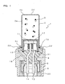
- Fig. 1 is a sectional view of a gas generator
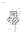
- Fig. 2 is a sectional view of an ignitor.
- a gas generator 1 includes a first cup 2, gas generants 3, an ignitor 4 and a holder 5.
- the first cup 2 includes a cylinder portion 2a, a bottom portion 2b on a tip end side or an upper end side of the cylinder portion 2a and a skirt portion 2c having an expanded diameter on an end side or a lower end side of the cylinder portion 2a, and has a bottomed cylindrical shape as a whole.
- metallic materials such as stainless steel, aluminum, brass and iron can be preferably used, but resins also can be used.
- a plurality of linear notches 2d radially extending from a center thereof is disposed.
- the skirt portion 2c having an expanded diameter of the first cup 2 functions as taper-like flange supported by the ignitor 4 and the holder 5 described later.
- the gas generants 3 are accommodated so as to directly come into contact with an internal periphery of the first cup 2. At the time of combustion of the gas generants 3 that are accommodated in the first cup 2, the notches 2d are broken and thereby gas is directly released to motor vehicle safety devices such as a sheet belt pretensioner, a vehicular occupant restraint from forward movement, a movable headrest and a battery current breaker that are not shown in the drawing.
- motor vehicle safety devices such as a sheet belt pretensioner, a vehicular occupant restraint from forward movement, a movable headrest and a battery current breaker that are not shown in the drawing.
- the ignitor 4 as shown in Fig. 2, includes igniting agents 11; a second cup 12 therein the igniting agents 11 is accommodated; two pins 13, 14 erected so as to energize a current to ignite the igniting agents 11; a cap body 15 thereto the pins 13, 14 are attached; and a plug 16 that covers a lower portion of the second cup 12 and holds it.
- the igniting agents 11 ones that contain, for instance, zirconium, tungsten, potassium perchlorate and a binder can be used.
- the second cup 12 has a bottomed cylindrical shape in which a metallic internal cup 12a and an external cup 12b made of an insulating resin are superposed.
- the igniting agents 11 is accommodated inside of the second cup 12, and the second cup is clogged with a metallic cap body 15.
- the pin 13 is connected to a lower portion of the cap body 15 in an erected manner, and the pin 14 is penetratingly attached through a glass seal 15b that is an insulator to a through hole 15a in a center of the cap body 15.
- an electric bridge wire 17 that is heated owing to the energization is attached.
- a lower end of the metallic internal cup 12a and a lower side periphery of the cap body 15 are connected by laser welding 18 or the like.
- the plug 16 is a resin molded body and, with a lower end side of the second cup 12 and portions projected from the cap body 15 of the pins 13, 14 covered, holds these.
- An external periphery of the plug 16 has a shape that includes a step portion 16a in a boundary portion with the second cup 12; a tapered portion 16b with an expanded diameter; a cylinder solid portion with a large diameter 16c; a tapered portion with a contracted diameter 16d; and a cylinder solid portion with a small diameter 16e.
- resins that can be used in resin molding of the plug 16 ones in which resins such as polybutylene terephthalate, polyethylene terephthalate, nylon 6, nylon 66, nylon 12, polyphenylene sulfide, polyphenylene oxide, polyethylene imide, polyether imide, polyether ether ketone or polyether sulfone contain glass fiber, carbon or the like can be cited.
- an external periphery of the second cup 12 is engaged in an internal periphery of the first cup 2. Both are preferably brought into substantial close contact, a separation between both is preferably 1 mm or less, and more preferably 0.2 mm or less.
- the skirt portion with an expanded diameter 2c of the first cup 2 has a length that runs along the sealing portion with an expanded diameter 16b (Fig. 2) of the plug 16.
- an O-ring 19 is engaged as a sealing member and pressed down with a root of the skirt portion 2c with an expanded diameter of the first cup 2.
- the holder 5 is made of a metallic material such as stainless steel, aluminum, brass or iron or a hard resin material.
- the holder 5 includes a first hole 21 that is used to engage from above, of the external periphery of the plug 16 of the ignitor 4, the cylinder solid portion with a large diameter 16b, the contracted diameter portion 16c and the cylinder solid portion with a small diameter 16d; a second hole 22 that allows engaging a shorting clip 6 from below; and a protruded portion 23 that extends upward from the first hole 21 and can be compressed inward or crimped.
- the holder 5 allows locating the ignitor 4 in a center of the first cup 2, and fixes a position of the first cup 2 and holds the plug 16 of the ignitor 4.
- the shorting clip 6 is attached to keep two pins 13, 14 of the ignitor 4 in a shorted state.
- the shorting clip 6 is used until the gas generator 1 is attached in a normal state to prevent malfunction due to static electricity from occurring.
- the gas generator 1 thus constituted can be manufactured according to the following procedure.
- the first cup 2 therein a predetermined amount of gas generants 3 is accommodated is prepared.
- a set of the first cup 2 and the ignitor 4 is engaged in the first hole 21 of the holder 5, the projection 23 is crimped toward the plug 16 of the ignitor 4, and thereby the first cup 2 and the ignitor 4 are co-fastened and fixed to the holder 5.
- the O-ring 19 intervened between the first cup 2 and the ignitor 4 is pressed down in a crashing manner and hermetically seals between the ignitor 4 of the first cup 2 and the second cup 12 of the ignitor 4.
- the gas generants that can be used in a gas generator according to the invention are one that contain, for instance, a nitrogen-containing organic compound and an inorganic compound, and, as needs arise, additives may be added thereto.
- the nitrogen-containing organic compound mainly plays the role of a fuel component.
- the inorganic compound mainly plays the role of an oxidizing component.
- nitrogen-containing organic compounds at least one kind or more selected from a group of amino-tetrazole, guanidine nitrate, and nitroguanidine can be cited.
- inorganic compounds at least one kind or more selected from a group of strontium nitrate, ammonium nitrate, potassium nitrate, ammonium perchlorate, and potassium perchlorate can be cited.
- molybdenum trioxide that is a self-igniting catalyst
- a binder and so on can be cited.
- the binder at least one kind or more selected from a group of guar gum, methyl cellulose, carboxy methyl cellulose, nitrocellulose, water-soluble cellulose ether, and polyethylene glycol can be cited.
- the preferable gas generants are gas generants that contain as the nitrogen-containing organic compounds, 5-aminotetrazole and guanidine nitrate; as the inorganic compound, strontium nitrate and ammonium perchlorate; as the self-igniting catalyst, molybdenum trioxide; and as the binder, guar gum.
- the more preferable gas generants are one that contain from 10 to 30 % by mass of 5-aminotetrazole and from 15 to 35 % by mass of guanidine nitrate as the nitrogen-containing organic compound; from 10 to 30 % by mass of strontium nitrate and from 15 to 35 % by mass ammonium perchlorate as the inorganic compound; from 1 to 10 % by mass of molybdenum trioxide as the self-igniting catalyst; and from 1 to 10 % by mass of guar gum as the binder.
- a manufacturing method of the gas generants 3 will be explained. Predetermined amounts of the respective components of the gas generants 3 are weighed. After weighing, the respective components are thoroughly blended with a V blender. To the above mixture, from 10 to 30 % by mass of water is added followed by further blending. A wet mixture is kneaded with a kneader and thereby a glutinous mass is obtained. This mass is formed into a desired shape by use of a vacuum extruder. This is dried first at 60 degree centigrade for 15 hr, then at 100 degree centigrade for 5 hr, and thereby desired gas generants 3 are obtained. Furthermore, so far used smokeless powder also can be excellently used as the gas generants 3.
- Fig. 4 specifications of an example of a gas generator involving the invention that is used in the 10 cc bomb test and of an conventional gas generator that is used in a sheet belt pretensioner are shown together.
- a gas generation amount is made the same with that of the gas generator used in the conventional sheet belt pretensioner.
- a pressure measurement bomb made of a robust material such as stainless steel or the like is used.
- the gas generator is attached to a bomb jig disposed to the pressure measurement bomb.
- the bomb jig one that is larger by from 0.2 to 0.4 mm in an external diameter than a cup portion of the gas generator is used.
- the gas generator is connected to a constant current pulse generator with an ignition current cable, an ignition current is energized (0.8 A x 2 ms), and thereby the gas generator is actuated.
- a pressure of a combustion gas from the gas generator is measured through a pressure sensor disposed in a combustion chamber with a measurement instrument such as an oscilloscope and the like.
- an output of the gas generator is thus measured. Results are shown in Fig. 5.
- the gas generator according to the invention in comparison with the conventional gas generator, can be made smaller in size, and can extract a higher pressure (high generated maximum pressure) because with the same amount of the gas generants an internal diameter of the cylinder assumed bomb jig can be made slender.
- the gas generator involving the invention since a fixing structure of the ignitor and the cup to the holder can be shared, the structure can be simplified and the sealing performance can be improved. Furthermore, the gas generator according to the invention, in comparison with the conventional gas generator, at the same amount of the gas generants, can be made slender in an internal diameter of the cylinder of the motor vehicle safety device. Accordingly, a higher output (high generated maximum pressure) can be extracted.
Landscapes
- Engineering & Computer Science (AREA)
- General Engineering & Computer Science (AREA)
- Mechanical Engineering (AREA)
- Air Bags (AREA)
- Feeding, Discharge, Calcimining, Fusing, And Gas-Generation Devices (AREA)
- Automotive Seat Belt Assembly (AREA)
Abstract
In a first cup 2, a second cup 12 of an ignitor 4 is
inserted in an engaged state, a sealing member 19 is disposed
between an end 2c of the first cup 2 and the ignitor 4, and
the end 2c and the ignitor 4 are fixed by co-fastening due
to crimping a holder 5 toward the ignitor 4.
Description
The present invention relates to a small size gas
generator that is used to actuate, in the event of emergency
(at the time of motor vehicle collision), a motor vehicle
safety device having movable parts such as a sheet belt
pretensioner, a vehicular occupant restraint from forward
movement, a movable headrest and a battery current breaker.
The gas generator is attached to, for instance, a
cylinder, actuates a piston owing to a pressure of a generated
gas, and thereby actuates, with a driving force thereof, the
motor vehicle safety device.
A conventional gas generator has a structure in which
an ignitor that is ignited by an actuation current is fixed
through a first sealing member to a first fixing portion
inside of a holder by crimping or the like, a cup that
accommodates gas generants is put so as to cover the ignitor,
and an end of the cup is fixed through a second sealing member
to a second fixing portion outside of the holder by crimping
or the like.
The gas generator, in order to fix the cup that has
accommodated the gas generants against the holder with the
cup shielded from ambient air, separately from the first
fixing portion that fixes the internal ignitor, has the second
fixing portion that fixes an external end of the holder.
Furthermore, the holder is separately provided with the first
sealing member between the ignitor and the holder and the
second sealing member between the cup and the holder.
The conventional gas generator has two fixing portions
and two sealing portions, and two portions each have to be
unfailingly fixed and sealed. Furthermore, since two fixing
portions are separately located, an external diameter is
forced to be larger, resulting in difficulty in coping with
a smaller size of a device and in obtaining higher output
power.
The present invention was performed in view of such
conventional problems and intends to provide a gas generator
in which fixing structures of an ignitor to a holder and that
of a cup to the holder can be shared and the sealing also can
be securely performed.
Furthermore, by providing a gas generator having a
slender external diameter, in the above safety device, a
slender cylinder can be used; as a result, at the same use
amount of the gas generants, an output higher than ever is
intended to be extracted.
A gas generator according to the invention includes a
bottomed cylindrical first cup that accommodates gas
generants that generate a gas owing to combustion; an ignitor
disposed partially inserted into the first cup; and a holder
that covers the ignitor and holds an end side of the first
cup: wherein the end of the first cup and the ignitor are fixed
by co-fastening the holder to the ignitor.
The end of the first cup and the ignitor are fixed by
co-fastening the holder toward the ignitor, accordingly the
ignitor and the end of the first cup are fixed against the
holder at one place. Accordingly, manufacture can be
conveniently performed and a structure can be simplified,
resulting in realizing a smaller size gas generator.
Furthermore, the gas generator according to the
invention is provided with a sealing member between the end
of the first cup and the ignitor.
When the sealing member between the end of the first cup
and the ignitor operates, gas generants in the first cup is
hermetically sealed covered with the ignitor.
Still furthermore, in the gas generator according to the
invention, the ignitor includes a second cup that
accommodates igniting agents; and a plug that holds the second
cup: wherein the exterior of the second cup is inserted inside
of the first cup in an engaged state.
Since the second cup that accommodates the igniting
agents is inserted in an engaged state in the first cup that
accommodates the gas generants, the first cup is guided by
the second cup and fixed to the holder in a state where the
first cup is held by the ignitor. Furthermore, since the
second cup is reinforced with the first cup, an external
periphery of the second cup and an internal periphery of the
first cup are preferably substantially the same.
Furthermore, in the gas generator according to the
invention, the end of the first cup is inserted so as to touch
the plug, and the sealing member is disposed in a boundary
portion between the second cup and the plug.
With the sealing member inserting into the boundary
portion between the second cup and the plug, the end of the
first cup touches the plug; accordingly, a position of the
sealing member such as an O-ring is stabilized.
Still furthermore, in the gas generator according to the
invention, the end of the first cup and the plug thereto the
end touches each are formed in a mutually tapered surface.
A touching state of the end of the first cup and the plug
can be stabilized. In addition, owing to the tapered surface,
the gas generants can be easily accommodated in the first cup.
Furthermore, in the gas generator according to the
invention, the ignitor and the end of the first cup are fixed
by crimping the holder toward the ignitor.
When the touching between the end of the first cup and
the plug is formed on the tapered surface and the holder is
crimped toward the plug, the co-fastening can be solidly
performed.
In the following, an example of an embodiment of the
invention will be explained with reference to the drawings.
Fig. 1 is a sectional view of a gas generator, and Fig. 2 is
a sectional view of an ignitor.
In Fig. 1, a gas generator 1 includes a first cup 2, gas
generants 3, an ignitor 4 and a holder 5.
The first cup 2 includes a cylinder portion 2a, a bottom
portion 2b on a tip end side or an upper end side of the
cylinder portion 2a and a skirt portion 2c having an expanded
diameter on an end side or a lower end side of the cylinder
portion 2a, and has a bottomed cylindrical shape as a whole.
As materials of the first cup 2, metallic materials such as
stainless steel, aluminum, brass and iron can be preferably
used, but resins also can be used. On an external surface
of the bottom portion 2b of the first cup 2, a plurality of
linear notches 2d radially extending from a center thereof
is disposed. The skirt portion 2c having an expanded diameter
of the first cup 2 functions as taper-like flange supported
by the ignitor 4 and the holder 5 described later.
The gas generants 3 are accommodated so as to directly
come into contact with an internal periphery of the first cup
2. At the time of combustion of the gas generants 3 that are
accommodated in the first cup 2, the notches 2d are broken
and thereby gas is directly released to motor vehicle safety
devices such as a sheet belt pretensioner, a vehicular
occupant restraint from forward movement, a movable headrest
and a battery current breaker that are not shown in the
drawing.
The ignitor 4, as shown in Fig. 2, includes igniting
agents 11; a second cup 12 therein the igniting agents 11 is
accommodated; two pins 13, 14 erected so as to energize a
current to ignite the igniting agents 11; a cap body 15 thereto
the pins 13, 14 are attached; and a plug 16 that covers a lower
portion of the second cup 12 and holds it. As the igniting
agents 11, ones that contain, for instance, zirconium,
tungsten, potassium perchlorate and a binder can be used.
The second cup 12 has a bottomed cylindrical shape in
which a metallic internal cup 12a and an external cup 12b made
of an insulating resin are superposed. The igniting agents
11 is accommodated inside of the second cup 12, and the second
cup is clogged with a metallic cap body 15. The pin 13 is
connected to a lower portion of the cap body 15 in an erected
manner, and the pin 14 is penetratingly attached through a
glass seal 15b that is an insulator to a through hole 15a in
a center of the cap body 15. Between an upper end of the pin
14 and a top surface of the cap body 15, an electric bridge
wire 17 that is heated owing to the energization is attached.
A lower end of the metallic internal cup 12a and a lower side
periphery of the cap body 15 are connected by laser welding
18 or the like.
The plug 16 is a resin molded body and, with a lower end
side of the second cup 12 and portions projected from the cap
body 15 of the pins 13, 14 covered, holds these. An external
periphery of the plug 16 has a shape that includes a step
portion 16a in a boundary portion with the second cup 12; a
tapered portion 16b with an expanded diameter; a cylinder
solid portion with a large diameter 16c; a tapered portion
with a contracted diameter 16d; and a cylinder solid portion
with a small diameter 16e.
As resins that can be used in resin molding of the plug
16, ones in which resins such as polybutylene terephthalate,
polyethylene terephthalate, nylon 6, nylon 66, nylon 12,
polyphenylene sulfide, polyphenylene oxide, polyethylene
imide, polyether imide, polyether ether ketone or polyether
sulfone contain glass fiber, carbon or the like can be cited.
In Fig. 1, in an internal periphery of the first cup 2,
an external periphery of the second cup 12 is engaged. Both
are preferably brought into substantial close contact, a
separation between both is preferably 1 mm or less, and more
preferably 0.2 mm or less. The skirt portion with an expanded
diameter 2c of the first cup 2 has a length that runs along
the sealing portion with an expanded diameter 16b (Fig. 2)
of the plug 16. Along the step portion 16a (Fig. 2) in the
boundary portion with the second cup 12 of the plug 16, an
O-ring 19 is engaged as a sealing member and pressed down with
a root of the skirt portion 2c with an expanded diameter of
the first cup 2.
The holder 5 is made of a metallic material such as
stainless steel, aluminum, brass or iron or a hard resin
material. The holder 5 includes a first hole 21 that is used
to engage from above, of the external periphery of the plug
16 of the ignitor 4, the cylinder solid portion with a large
diameter 16b, the contracted diameter portion 16c and the
cylinder solid portion with a small diameter 16d; a second
hole 22 that allows engaging a shorting clip 6 from below;
and a protruded portion 23 that extends upward from the first
hole 21 and can be compressed inward or crimped. The holder
5 allows locating the ignitor 4 in a center of the first cup
2, and fixes a position of the first cup 2 and holds the plug
16 of the ignitor 4.
The shorting clip 6 is attached to keep two pins 13, 14
of the ignitor 4 in a shorted state. The shorting clip 6 is
used until the gas generator 1 is attached in a normal state
to prevent malfunction due to static electricity from
occurring.
The gas generator 1 thus constituted can be manufactured
according to the following procedure. The first cup 2 therein
a predetermined amount of gas generants 3 is accommodated is
prepared. The ignitor 4 in which along the step portion 16a
(Fig. 2) that is a boundary portion between the plug 16 and
the second cup 12 the O-ring 19 is engaged is prepared. Inside
of the first cup 2, the second cup 12 of the ignitor 4 is
engaged. It is confirmed that the skirt portion 2c having
an expanded diameter of the first cup 2 touches the tapered
portion 16b with an expanded diameter (Fig. 2) of the plug
16 and is in a state capable of pressing down the O-ring 19.
A set of the first cup 2 and the ignitor 4 is engaged
in the first hole 21 of the holder 5, the projection 23 is
crimped toward the plug 16 of the ignitor 4, and thereby the
first cup 2 and the ignitor 4 are co-fastened and fixed to
the holder 5. At this time, the O-ring 19 intervened between
the first cup 2 and the ignitor 4 is pressed down in a crashing
manner and hermetically seals between the ignitor 4 of the
first cup 2 and the second cup 12 of the ignitor 4.
In the next place, operations of the gas generator 1 will
be explained. When the gas generator 1 is connected to a
connector in a normal state, the short-circuited state due
to the shorting clip 6 is relieved. When in this state a
collision sensor (not shown in the drawing) senses a collision
of a motor vehicle, the pins 13, 14 erected in the ignitor
4 are energized. The bridge wire 17 in the ignitor 4 is heated
and thereby the igniting agents 11 is ignited. A weak portion
of a bottom of the second cup 12 is broken and through this
portion high temperature and high pressure gas and particles
are at a breath sprayed to the gas generants 3 in the first
cup 2. Thereby, the gas generants 3 are ignited. Subsequently,
a lot of gas generated within the first cup 2 owing to the
combustion of the gas generants 3 rapidly increase an internal
pressure of the first cup 2, finally breaks the notch portion
2d disposed at the bottom portion 2b of the first cup 2, and
is introduced into the motor vehicle safety devices such as
the sheet belt pretensioner, the occupant restraint from
forward movement, the movable headrest, and the battery
current breaker that are not shown in the drawing.
In the next place, a preferable gas generants 3 in the
first cup 2 will be explained. The gas generants that can
be used in a gas generator according to the invention are one
that contain, for instance, a nitrogen-containing organic
compound and an inorganic compound, and, as needs arise,
additives may be added thereto. The nitrogen-containing
organic compound mainly plays the role of a fuel component.
Furthermore, the inorganic compound mainly plays the role of
an oxidizing component.
As the nitrogen-containing organic compounds, at least
one kind or more selected from a group of amino-tetrazole,
guanidine nitrate, and nitroguanidine can be cited. As the
inorganic compounds, at least one kind or more selected from
a group of strontium nitrate, ammonium nitrate, potassium
nitrate, ammonium perchlorate, and potassium perchlorate can
be cited.
As the additive, molybdenum trioxide that is a
self-igniting catalyst can be cited. Furthermore, as other
additives that can be added to the gas generants, a binder
and so on can be cited. As the binder, at least one kind or
more selected from a group of guar gum, methyl cellulose,
carboxy methyl cellulose, nitrocellulose, water-soluble
cellulose ether, and polyethylene glycol can be cited.
The preferable gas generants are gas generants that
contain as the nitrogen-containing organic compounds,
5-aminotetrazole and guanidine nitrate; as the inorganic
compound, strontium nitrate and ammonium perchlorate; as the
self-igniting catalyst, molybdenum trioxide; and as the
binder, guar gum. The more preferable gas generants are one
that contain from 10 to 30 % by mass of 5-aminotetrazole and
from 15 to 35 % by mass of guanidine nitrate as the
nitrogen-containing organic compound; from 10 to 30 % by mass
of strontium nitrate and from 15 to 35 % by mass ammonium
perchlorate as the inorganic compound; from 1 to 10 % by mass
of molybdenum trioxide as the self-igniting catalyst; and
from 1 to 10 % by mass of guar gum as the binder.
A manufacturing method of the gas generants 3 will be
explained. Predetermined amounts of the respective
components of the gas generants 3 are weighed. After weighing,
the respective components are thoroughly blended with a V
blender. To the above mixture, from 10 to 30 % by mass of
water is added followed by further blending. A wet mixture
is kneaded with a kneader and thereby a glutinous mass is
obtained. This mass is formed into a desired shape by use
of a vacuum extruder. This is dried first at 60 degree
centigrade for 15 hr, then at 100 degree centigrade for 5 hr,
and thereby desired gas generants 3 are obtained. Furthermore,
so far used smokeless powder also can be excellently used as
the gas generants 3.
Effects of the gas generator 1 involving the above
embodiment will be explained below.
The embodiment according to the invention is not
restricted to the above one but may be modified as shown for
instance in the following.
In the following, results of a 10 cc bomb test with an
example of a gas generator involving the invention are shown.
In Fig. 4, specifications of an example of a gas
generator involving the invention that is used in the 10 cc
bomb test and of an conventional gas generator that is used
in a sheet belt pretensioner are shown together. In the gas
generator according to the invention, in order to compare with
the conventional gas generator, a gas generation amount is
made the same with that of the gas generator used in the
conventional sheet belt pretensioner.
In the 10 cc bomb test, as shown in Fig. 6, a pressure
measurement bomb made of a robust material such as stainless
steel or the like is used. The gas generator is attached to
a bomb jig disposed to the pressure measurement bomb. As the
bomb jig, one that is larger by from 0.2 to 0.4 mm in an
external diameter than a cup portion of the gas generator is
used. The gas generator is connected to a constant current
pulse generator with an ignition current cable, an ignition
current is energized (0.8 A x 2 ms), and thereby the gas
generator is actuated. A pressure of a combustion gas from
the gas generator is measured through a pressure sensor
disposed in a combustion chamber with a measurement
instrument such as an oscilloscope and the like. In the 10
cc bomb test, an output of the gas generator is thus measured.
Results are shown in Fig. 5.
As shown in Figs. 4 and 5, it is found that the gas
generator according to the invention, in comparison with the
conventional gas generator, can be made smaller in size, and
can extract a higher pressure (high generated maximum
pressure) because with the same amount of the gas generants
an internal diameter of the cylinder assumed bomb jig can be
made slender.
As detailed in the above, according to the gas generator
involving the invention, since a fixing structure of the
ignitor and the cup to the holder can be shared, the structure
can be simplified and the sealing performance can be improved.
Furthermore, the gas generator according to the invention,
in comparison with the conventional gas generator, at the same
amount of the gas generants, can be made slender in an internal
diameter of the cylinder of the motor vehicle safety device.
Accordingly, a higher output (high generated maximum
pressure) can be extracted.
Claims (10)
- A gas generator comprising a bottomed cylindrical first cup that accommodates gas generants that generate a gas owing to combustion; an ignitor disposed partially inserted in the first cup; and a holder that covers the ignitor and holds an end side of the first cup;
wherein the end of the first cup and the ignitor are fixed by co-fastening the holder toward the ignitor. - The gas generator as set forth in claim 1:
wherein a sealing member is disposed between the end of the first cup and the ignitor. - The gas generator as set forth in claim 1:
wherein the ignitor includes a second cup that accommodates igniting agents and a plug that holds the second cup;
wherein the second cup is inserted in the first cup in an engaged state where an exterior of the second cup engages in an interior of the first cup. - The gas generator as set forth in claim 3:
wherein the end of the first cup is inserted so as to touch the plug, and the sealing member is disposed in a boundary portion between the second cup and the plug. - The gas generator as set forth in claim 4:
wherein the end of the first cup and the plug portion touching the end of the first cup are formed into a mutually tapered shape. - The gas generator as set forth in claim 5:
wherein the ignitor and the end of the first cup are fixed by crimping the holder toward the ignitor. - The gas generator as set forth in claim 2:
wherein the ignitor includes a second cup that accommodates igniting agents and a plug that holds the second cup;
wherein the second cup is inserted in the first cup in an engaged state where an exterior of the second cup engages in an interior of the first cup. - The gas generator as set forth in claim 7:
wherein the end of the first cup is inserted so as to touch the plug, and the sealing member is disposed in a boundary portion between the second cup and the plug. - The gas generator as set forth in claim 8:
wherein the end of the first cup and the plug portion touching the end of the first cup are formed into a mutually tapered shape. - The gas generator as set forth in claim 9:
wherein the ignitor and the end of the first cup are fixed by crimping the holder toward the ignitor.
Applications Claiming Priority (3)
| Application Number | Priority Date | Filing Date | Title |
|---|---|---|---|
| JP2001144135 | 2001-05-15 | ||
| JP2001144135 | 2001-05-15 | ||
| PCT/JP2002/004684 WO2002092400A1 (en) | 2001-05-15 | 2002-05-15 | Gas generator |
Publications (2)
| Publication Number | Publication Date |
|---|---|
| EP1396394A1 true EP1396394A1 (en) | 2004-03-10 |
| EP1396394A4 EP1396394A4 (en) | 2004-12-08 |
Family
ID=18990135
Family Applications (1)
| Application Number | Title | Priority Date | Filing Date |
|---|---|---|---|
| EP02769601A Withdrawn EP1396394A4 (en) | 2001-05-15 | 2002-05-15 | Gas generator |
Country Status (6)
| Country | Link |
|---|---|
| US (1) | US20040160046A1 (en) |
| EP (1) | EP1396394A4 (en) |
| JP (1) | JPWO2002092400A1 (en) |
| CN (1) | CN1509240A (en) |
| CZ (1) | CZ20033416A3 (en) |
| WO (1) | WO2002092400A1 (en) |
Cited By (2)
| Publication number | Priority date | Publication date | Assignee | Title |
|---|---|---|---|---|
| DE102007057551A1 (en) * | 2007-11-29 | 2009-06-04 | Diehl Bgt Defence Gmbh & Co. Kg | Miniaturized force element |
| EP2589920A3 (en) * | 2011-11-02 | 2015-05-13 | Indet Safety Systems a.s. | High performance initiator |
Families Citing this family (13)
| Publication number | Priority date | Publication date | Assignee | Title |
|---|---|---|---|---|
| JP3803636B2 (en) | 2002-12-26 | 2006-08-02 | 本田技研工業株式会社 | Ignition device for bus connection |
| EP1849519A4 (en) * | 2005-01-21 | 2011-05-18 | Nippon Kayaku Kk | Gas generator and method of manufacturing the same |
| JP4907931B2 (en) * | 2005-09-15 | 2012-04-04 | 日本化薬株式会社 | Gas generator |
| DE102006002435A1 (en) * | 2006-01-12 | 2007-07-26 | Takata-Petri Ag | Method for producing a gas generator and gas generator produced by the method |
| CN101121396B (en) * | 2006-08-09 | 2010-05-12 | 比亚迪股份有限公司 | Electric ignition tube for gas generator and ignition method thereof |
| JP5381932B2 (en) * | 2010-03-02 | 2014-01-08 | 豊田合成株式会社 | Gas generator |
| JP5450306B2 (en) * | 2010-07-29 | 2014-03-26 | 株式会社ダイセル | Gas generator |
| DE102012010608B4 (en) * | 2012-05-16 | 2025-02-13 | Zf Airbag Germany Gmbh | Igniter and method for producing an igniter for a gas generator |
| JP7266412B2 (en) | 2019-01-18 | 2023-04-28 | 日本化薬株式会社 | gas generator |
| CN110530605B (en) * | 2019-08-23 | 2021-07-13 | 南京理工大学 | An underwater vehicle exhaust experiment device |
| JP7284044B2 (en) * | 2019-08-30 | 2023-05-30 | 株式会社ダイセル | Ignitor holding structure |
| JP7553375B2 (en) | 2021-02-04 | 2024-09-18 | 株式会社ダイセル | Igniter assembly and gas generator |
| CN114407824B (en) * | 2021-12-14 | 2022-12-02 | 均胜汽车安全系统(长兴)有限公司 | Gas generator with ignitions and explosion functions of igniters |
Family Cites Families (16)
| Publication number | Priority date | Publication date | Assignee | Title |
|---|---|---|---|---|
| DE3425836A1 (en) * | 1984-07-13 | 1986-01-23 | Bayern-Chemie Gesellschaft für flugchemische Antriebe mbH, 8261 Aschau | GAS GENERATOR |
| US5140906A (en) * | 1991-11-05 | 1992-08-25 | Ici Americas, Inc. | Airbag igniter having double glass seal |
| DE4435319A1 (en) * | 1994-10-01 | 1996-04-04 | Temic Bayern Chem Airbag Gmbh | Ignition unit for a gas generator of a passive restraint system |
| FR2754050B1 (en) * | 1996-10-01 | 1998-10-30 | Livbag Snc | PYROTECHNIC GAS MICROGENERATOR WITH BLOCKED TWO-WIRE SOCKET |
| US5951042A (en) * | 1997-11-06 | 1999-09-14 | Trw Inc. | Vehicle occupant protection apparatus |
| JP2000273090A (en) * | 1999-01-22 | 2000-10-03 | Nippon Koki Co Ltd | Guanylaminotetrazole, gas generating agent for automotive safety devices based on this guanylaminotetrazole |
| GB2347485A (en) * | 1999-03-05 | 2000-09-06 | Breed Automotive Tech | Pretensioner |
| JP2000292099A (en) * | 1999-04-08 | 2000-10-20 | Nippon Kayaku Co Ltd | Squib and squib device |
| JP2000292098A (en) * | 1999-04-08 | 2000-10-20 | Nippon Kayaku Co Ltd | Squib |
| JP2000329500A (en) * | 1999-05-17 | 2000-11-30 | Nippon Kayaku Co Ltd | Squib |
| JP2001021293A (en) * | 1999-07-02 | 2001-01-26 | Nippon Kayaku Co Ltd | Squib and squib manufacturing method |
| JP2001088653A (en) * | 1999-07-21 | 2001-04-03 | Nippon Koki Co Ltd | Gas generator |
| EP1216898A4 (en) * | 1999-08-23 | 2004-12-08 | Nippon Kayaku Kk | Gas generator for actuating vehicle passenger constrainer |
| JP4426079B2 (en) * | 1999-09-27 | 2010-03-03 | ダイセル化学工業株式会社 | Initiator assembly |
| JP4864234B2 (en) * | 2000-06-22 | 2012-02-01 | 株式会社ダイセル | Gas generator for airbag |
| US6454306B1 (en) * | 2000-08-01 | 2002-09-24 | Trw Inc. | Gas generator for seat belt pretensioner |
-
2002
- 2002-05-15 CN CNA028101235A patent/CN1509240A/en active Pending
- 2002-05-15 EP EP02769601A patent/EP1396394A4/en not_active Withdrawn
- 2002-05-15 JP JP2002589311A patent/JPWO2002092400A1/en active Pending
- 2002-05-15 CZ CZ20033416A patent/CZ20033416A3/en unknown
- 2002-05-15 WO PCT/JP2002/004684 patent/WO2002092400A1/en not_active Ceased
- 2002-05-15 US US10/477,265 patent/US20040160046A1/en not_active Abandoned
Cited By (3)
| Publication number | Priority date | Publication date | Assignee | Title |
|---|---|---|---|---|
| DE102007057551A1 (en) * | 2007-11-29 | 2009-06-04 | Diehl Bgt Defence Gmbh & Co. Kg | Miniaturized force element |
| DE102007057551B4 (en) * | 2007-11-29 | 2011-11-24 | Diehl Bgt Defence Gmbh & Co. Kg | Miniaturized force element |
| EP2589920A3 (en) * | 2011-11-02 | 2015-05-13 | Indet Safety Systems a.s. | High performance initiator |
Also Published As
| Publication number | Publication date |
|---|---|
| EP1396394A4 (en) | 2004-12-08 |
| CZ20033416A3 (en) | 2004-04-14 |
| US20040160046A1 (en) | 2004-08-19 |
| CN1509240A (en) | 2004-06-30 |
| JPWO2002092400A1 (en) | 2004-08-26 |
| WO2002092400A1 (en) | 2002-11-21 |
Similar Documents
| Publication | Publication Date | Title |
|---|---|---|
| US20040160046A1 (en) | Gas generator | |
| EP1441193B1 (en) | Initiator and gas generator | |
| US20020189487A1 (en) | Gas generator | |
| EP1424249B1 (en) | Gas generator | |
| EP1541429B1 (en) | Gas generator | |
| US7530310B2 (en) | Metal holder with electrode pin, method of manufacturing the metal holder, and gas generator | |
| US6009809A (en) | Bridgewire initiator | |
| EP1227294A1 (en) | Electric type initiator and pretensioner | |
| JP4244365B2 (en) | Ignition composition and igniter using the ignition composition | |
| JPWO2007083663A1 (en) | Compact gas generator and pretensioner system for gas actuator | |
| WO2013118405A1 (en) | Gas generator | |
| JP2000292100A (en) | Electric ignition type gas generator | |
| US20200172044A1 (en) | Gas generator | |
| JP4537210B2 (en) | Gas generator | |
| CZ20014541A3 (en) | Percussion cap and process for producing thereof | |
| WO2023171689A1 (en) | Ignition device | |
| CN113661097A (en) | The gas generator | |
| US20060208474A1 (en) | Gas producer | |
| JP2002200420A (en) | Gas generator | |
| JP2002239371A (en) | Gas generator | |
| JP2000329500A (en) | Squib | |
| KR100618554B1 (en) | gas producer | |
| JPH09309397A (en) | Airbag device | |
| JP2004114826A (en) | Gas generator | |
| CN120112440A (en) | Gas generator |
Legal Events
| Date | Code | Title | Description |
|---|---|---|---|
| PUAI | Public reference made under article 153(3) epc to a published international application that has entered the european phase |
Free format text: ORIGINAL CODE: 0009012 |
|
| 17P | Request for examination filed |
Effective date: 20031212 |
|
| AK | Designated contracting states |
Kind code of ref document: A1 Designated state(s): AT BE CH CY DE DK ES FI FR GB GR IE IT LI LU MC NL PT SE TR |
|
| AX | Request for extension of the european patent |
Extension state: AL LT LV MK RO SI |
|
| A4 | Supplementary search report drawn up and despatched |
Effective date: 20041025 |
|
| STAA | Information on the status of an ep patent application or granted ep patent |
Free format text: STATUS: THE APPLICATION HAS BEEN WITHDRAWN |
|
| 18W | Application withdrawn |
Effective date: 20041210 |