EP1396314A1 - Cable arrangement of a robot with means for electrically shielding the cables - Google Patents
Cable arrangement of a robot with means for electrically shielding the cables Download PDFInfo
- Publication number
- EP1396314A1 EP1396314A1 EP03255488A EP03255488A EP1396314A1 EP 1396314 A1 EP1396314 A1 EP 1396314A1 EP 03255488 A EP03255488 A EP 03255488A EP 03255488 A EP03255488 A EP 03255488A EP 1396314 A1 EP1396314 A1 EP 1396314A1
- Authority
- EP
- European Patent Office
- Prior art keywords
- forearm
- cables
- camera
- cable
- robot
- Prior art date
- Legal status (The legal status is an assumption and is not a legal conclusion. Google has not performed a legal analysis and makes no representation as to the accuracy of the status listed.)
- Granted
Links
- 210000000245 forearm Anatomy 0.000 claims abstract description 97
- 210000000707 wrist Anatomy 0.000 claims description 20
- 238000001514 detection method Methods 0.000 claims description 6
- 239000004020 conductor Substances 0.000 abstract description 3
- 239000012636 effector Substances 0.000 description 8
- 230000000007 visual effect Effects 0.000 description 8
- 238000005452 bending Methods 0.000 description 3
- 230000002093 peripheral effect Effects 0.000 description 3
- 230000005540 biological transmission Effects 0.000 description 2
- 230000008054 signal transmission Effects 0.000 description 2
- 206010016275 Fear Diseases 0.000 description 1
- 238000011144 upstream manufacturing Methods 0.000 description 1
Images



Classifications
-
- H—ELECTRICITY
- H05—ELECTRIC TECHNIQUES NOT OTHERWISE PROVIDED FOR
- H05K—PRINTED CIRCUITS; CASINGS OR CONSTRUCTIONAL DETAILS OF ELECTRIC APPARATUS; MANUFACTURE OF ASSEMBLAGES OF ELECTRICAL COMPONENTS
- H05K9/00—Screening of apparatus or components against electric or magnetic fields
- H05K9/0073—Shielding materials
- H05K9/0098—Shielding materials for shielding electrical cables
-
- B—PERFORMING OPERATIONS; TRANSPORTING
- B25—HAND TOOLS; PORTABLE POWER-DRIVEN TOOLS; MANIPULATORS
- B25J—MANIPULATORS; CHAMBERS PROVIDED WITH MANIPULATION DEVICES
- B25J13/00—Controls for manipulators
- B25J13/08—Controls for manipulators by means of sensing devices, e.g. viewing or touching devices
- B25J13/085—Force or torque sensors
-
- B—PERFORMING OPERATIONS; TRANSPORTING
- B25—HAND TOOLS; PORTABLE POWER-DRIVEN TOOLS; MANIPULATORS
- B25J—MANIPULATORS; CHAMBERS PROVIDED WITH MANIPULATION DEVICES
- B25J19/00—Accessories fitted to manipulators, e.g. for monitoring, for viewing; Safety devices combined with or specially adapted for use in connection with manipulators
- B25J19/0025—Means for supplying energy to the end effector
- B25J19/0029—Means for supplying energy to the end effector arranged within the different robot elements
-
- B—PERFORMING OPERATIONS; TRANSPORTING
- B25—HAND TOOLS; PORTABLE POWER-DRIVEN TOOLS; MANIPULATORS
- B25J—MANIPULATORS; CHAMBERS PROVIDED WITH MANIPULATION DEVICES
- B25J19/00—Accessories fitted to manipulators, e.g. for monitoring, for viewing; Safety devices combined with or specially adapted for use in connection with manipulators
- B25J19/0075—Means for protecting the manipulator from its environment or vice versa
-
- B—PERFORMING OPERATIONS; TRANSPORTING
- B25—HAND TOOLS; PORTABLE POWER-DRIVEN TOOLS; MANIPULATORS
- B25J—MANIPULATORS; CHAMBERS PROVIDED WITH MANIPULATION DEVICES
- B25J19/00—Accessories fitted to manipulators, e.g. for monitoring, for viewing; Safety devices combined with or specially adapted for use in connection with manipulators
- B25J19/02—Sensing devices
- B25J19/021—Optical sensing devices
- B25J19/023—Optical sensing devices including video camera means
-
- Y—GENERAL TAGGING OF NEW TECHNOLOGICAL DEVELOPMENTS; GENERAL TAGGING OF CROSS-SECTIONAL TECHNOLOGIES SPANNING OVER SEVERAL SECTIONS OF THE IPC; TECHNICAL SUBJECTS COVERED BY FORMER USPC CROSS-REFERENCE ART COLLECTIONS [XRACs] AND DIGESTS
- Y10—TECHNICAL SUBJECTS COVERED BY FORMER USPC
- Y10T—TECHNICAL SUBJECTS COVERED BY FORMER US CLASSIFICATION
- Y10T74/00—Machine element or mechanism
- Y10T74/20—Control lever and linkage systems
- Y10T74/20207—Multiple controlling elements for single controlled element
- Y10T74/20305—Robotic arm
- Y10T74/20311—Robotic arm including power cable or connector
Definitions
- the present invention relates to a cable laying structure for an industrial robot and in particular to a cable laying structure for connection with an analogue camera, a digital camera or a force sensor, which is attached to a wrist of an industrial robot of a horizontal or vertical articulated type.
- JP 2001-145634A discloses a cable laying structure for an endoscope (camera) attached to a robot.
- a camera utilized for a visual sensor is generally an analogue or digital camera.
- Analogue camera cables include a coaxial cable for transmitting a signal and a camera power cable
- digital camera cables include a signal cable for transmitting a digital picture signal and a camera power cable.
- utilized for the force-sensor cables are a signal cable for transmitting a detection signal of a strain gauge in a force sensor and a force-sensor power cable.
- a cable structure usually employed is the one in which the whole cables are covered with a shield member and a sheath so that the picture signal of the camera and the detection signal of strain gauge of the force sensor are not affected by noise from without and so that noise does not leak outside. Therefore, the sheath and shield of the camera and force-sensor cables are indispensable. Consequently, as for a robot with a forearm portion having a wrist shaft movable in a wide range, the cables are managed while being supported by an external supporting member in consideration of the life of the cables as in the mode in which the cables are hung outside the forearm by a hanger.
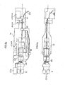
- FIGS. 1a and 1b illustrate the above arrangement.
- an analogue camera, or digital camera, or force sensor C/S alongside of the hand 5.
- the cables CB connected to the camera or force sensor C/S are introduced into the inside of robot mechanism from the connection panel 3 with a connector, that is fixed to a base 2 of a robot 1, and drawn out of the robot mechanism in the immediate vicinity of the forearm 4.
- the cables CB that have been drawn out of the robot main body are hung by the hanger 9 mounted closely to the forearm 4 and pass the outside of the forearm 4 to reach the camera or force sensor C/S.
- the camera cables that control the visual sensor (analogue or digital camera) mounted closely to the tip end of the robot wrist or the force-sensor cables that control the force sensor are embedded in the robot arm up to the immediate vicinity of the forearm. From the forearm portion to the tip end of the wrist, however, the cables are hung by the hanger or the like, that is attached on the outside of the robot arm, to be managed as far as the tip end of the robot wrist.
- the present invention provides a cable laying structure for a robot capable of preventing an interference with external devices in a periphery of a forearm of a robot.
- cables for an analogue or digital camera or a force sensor attached to a wrist of a horizontal or vertical articulated robot are arranged inside a body and an upper arm to a proximal portion of a forearm, and further the cables are led into the forearm from the proximal portion.
- the forearm is grounded to have the same electric potential as a base member of the robot to thereby electrically shielding the cables.
- the cables in the forearm are allowed to have a section where a shield and a sheath are removed to have a required degree of freedom of deformation. Accordingly, the cables passing through the forearm does not impede the motion of the forearm, and the motion of the forearm does not damage the cables.
- the sh ield and the sheath of the cables are removed to increase the degree of freedom of deformation, thereby preventing lives of the cables from being shortened by bending or twisting deformation of the cables through rotary motion of the forearm.
- the forearm has the same potential as the base member can be easily realized without employing a complicated structure since the forearm and the base member are both generally formed of a conductive material.
- the forearm is connected to the base member through a plurality of joints and links, so that the forearm can be made to have the same potential as the base member simply by electrically connecting the links by earth cables.
- the forearm and the base member may be directly connected to each other by earth cables or the like.
- the forearm can serve as a substitute for the shield member of the cable by grounding the robot forearm on the base member of the robot to make countermeasures against noise.
- FIG. 2 is a view showing the whole structure of a robot system including a robot in which camera cables (or force-sensor cables) are embedded in a forearm according to the present invention.
- a visual sensor camera (or force sensor) C/S and a hand 5 are attached at a tip end of the robot wrist.
- the camera (or force sensor) C/S and the hand 5 are connected to an end effector controller 30 by cables CB.
- an image processor for constructing the visual sensor with the camera is included in the end effector controller 30.
- the end effector controller 30 includes a device for converting an output of a strain gauge into, for example, six axial forces, and the like.
- a cable for drive control is illustrated together as cables CB in the lump.
- the end effector controller 30 is incorporated into the robot controller 20.
- FIGS. 3a through 5b a cable arrangement structure according to the embodiment will be explained.
- FIGS. 3a and 3b are an elevation view and a right side view showing a skeletal form of cable routing that is employed in the embodiment, respectively.
- FIGS. 4a and 4b are enlarged views showing cable management in the forearm portion in respect of the cable routing shown in FIGS. 3a and 3b, respectively.
- FIGS. 5a and 5b are a top view and a side view rather specifically showing the cable routing shown in FIGS. 3a and 3b, respectively.
- camera analogue or digital camera
- hand control cables and servo motor control cables are drawn into the robot mechanism 10 from the controller (the robot controller 20 or the end effector controller 30 illustrated in FIG. 2) through a connection panel 3 with a connector in the rear of a base 2 of a robot main body.
- force-sensor and hand control cables are drawn into the robot mechanism 10 from the controller (robot controller 20 or the end effector controller 30 illustrated in FIG. 2) through the connection panel 3 with a connector, that is situated in the rear of the base 2 of the robot main body.
- FIG. 3 shows these control cables with a reference character CB (in a dashed and a solid line) in the lump.
- the "control cables” include a transmission wire of input/output signals, a power supply wire, an air supply pipe, and the like, that are required for the camera (or force sensor), hand, and motor, respectively.
- the control cables CB drawn into the robot mechanism 10 are introduced into a hollow portion situated at the center of a revolving trunk 11. Cables that diverge from the servo motor control cables are connected to a first and a second axis driving motor (details not shown).
- the rest of the control cables are embedded in the robot arm along an upper arm portion 12 and guided to a forearm. 13.
- FIGS. 4a and 4b showing cable management
- FIGS. 5a and 5b showing a little more details.
- the cables that have diverged from the servo motor control cables are connected to a third axis driving motor (J3 motor) and a fourth axis driving motor (J4 motor) with respective gears.
- J3 motor third axis driving motor
- J4 motor fourth axis driving motor
- the rest of the cables are introduced into the inside of the forearm.
- a reference numeral 41 represents a clamp member disposed in the vicinity of the forearm portion, and the control cables for the J3 and J4 motors diverge therefrom.
- the camera cables (or force-sensor cables) that have been introduced into the inside of the forearm are subjected to bending and twisting near a rotation axis of the forearm when the forearm rotates (generally ⁇ 180° or more). Accordingly, in order to secure the life of the cables, the cables are introduced in the forearm 13 with a shield member and a sheath removed and fixed in front and rear portions of the forearm 13 by clamp members 42, 43 or the like.
- FIG. 5a shows one of the clamp members with reference numeral 42.
- FIGS. 6a and 6b are sectional views showing for contrast a state where the camera cables as an example are in the shield and the sheath and a state where the wiring is arranged in the forearm 13 with the shield and the sheath removed, respectively.
- the camera cables herein are those for an analogue camera and include coaxial cables 61, 62 and 63 and a signal cable 64 that are covered with a sheath 60 and a shield member 70.
- the coaxial cables 61, 62 and 63 and the signal cable 64 each accommodate a power cable 71, signal cables (control signal transmission cable 72 and analogue picture signal transmission cable 73) and the like in an allotted manner.
- a signal cable for transmitting a digital picture signal is used to transmit the digital picture signal.
- the force sensor is utilized, force-sensor cables are used, the force-sensor cables including a signal cable for transmitting a detection signal of a strain gauge in the force sensor and a force-sensor power cable.
- the cable laying takes place with the shield member and the sheath surrounding these cables removed at least in a certain cable-passing section in the forearm 13.
- the forearm 13 when not only the sheath but the shield is removed, signals are liable to be affected by noise from without, and noise is prone to leak outside.
- the base 2 of the robot main body and a proper. position of the forearm 13 formed of a conductive material are grounded at the same potential to utilize the forearm 13 in replacement of the shield member.
- the base 2 of the robot main body ought to be provided with a ground from the beginning. Under favour of this ground, the forearm 13 serves as a grounded shield if a proper position of the forearm 13 is connected to the base 2 of the robot main body.
- the forearm 13 Since the forearm 13 is connected to the base 2 of the robot main body with the joints therebetween, the forearm 13 can be grounded, for example, by electrically connecting the links constructing the connecting link structure between the base 2 of the robot main body and the forearm 13 by means of the earth cable, not shown.
- the earth cable whose end is grounded on the base 2 of the main body may be introduced into the inside of the forearm 13 together with the control cables and connected to the conductive member constructing the forearm 13 in the forearm 13.
- the forearm 13 and the base 2 of the robot main body may be directly connected to each other by means of an earth cable 50 to be grounded at the same potential.
- the camera control cables have upstream and downstream sections from the forearm 13 that are each covered with the shield member and the sheath, and it is possible to ground the shield member on the robot arm to reinforce the shield in an end portion.
- fixing loosen cables directly by a clamp member may cause the cables to be bent. Therefore, the camera cables are occasionally fixed after being bundled with the other control cables.
- the control cables CB that have been led to the inside of the forearm 13 are guided to the end effector-mounting face 44 in a state where the servo motor control cables are connected to a fifth axis driving motor (J5 motor) and a sixth axis driving motor (J6 motor) with respective gears, and the camera (or force sensor) control cables and hand control cables are drawn outside the forearm from one side face of a front portion of the forearm and wired along the side face of the forearm so as to have an extra length.
- J5 motor fifth axis driving motor
- J6 motor sixth axis driving motor
- the cables need to have a sufficient extra length around the wrist. It is often the case, however, that the robot equipped with a camera operates in the downward direction below a horizontal level, and an operating range of the wrist swing can be limited to approximately 130°. Accordingly, the sheath and the shield are not necessarily required to be removed from this part of the camera cables, and the camera cables can be managed along the forearm with the sheath and the shield attached.
- control cables that have been guided to the end effector-mounting face are housed in a circled state under favour of sufficiently wide space prepared for mounting the camera (or force sensor) C/S and the hand 5 offset, and eventually connected to the end effector including the camera (or force sensor).
- the robot equipped with a camera is generally required to do detection in an upper portion of work from various angles, thereby demanding an operating range of ⁇ 180° or more.
- the space for mounting the visual sensor and the hand on the end effector-mounting face offset is effectively used, it is possible to compactly organize the periphery of the end effector without preparing space exclusive for the cable arrangement.
- the above-mentioned structure makes it possible to complete the management of the camera cables and to pack the whole cables in the robot arm without making a projection over the periphery, thereby eliminating the problem of interference with peripheral devices in the subject area.
- the force sensor cables could be embedded in the forearm 13 in the same manner as the above-described structure.
- the present invention it is possible to improve the cable laying structure for connection with a camera or a sensor attached to a wrist of a robot, so that camera or force-sensor cables are arranged inside a forearm of the robot, thereby preventing an interference with peripheral devices in the periphery of the forearm.
- the robot forearm With a shielding function, picture signals and sensor signals in transmission through the cables are prevented from being affected by noises from outside, and also leakage of noises from the cables are prevented.
Landscapes
- Engineering & Computer Science (AREA)
- Robotics (AREA)
- Mechanical Engineering (AREA)
- Microelectronics & Electronic Packaging (AREA)
- Human Computer Interaction (AREA)
- Multimedia (AREA)
- Manipulator (AREA)
Abstract
Description
- The present invention relates to a cable laying structure for an industrial robot and in particular to a cable laying structure for connection with an analogue camera, a digital camera or a force sensor, which is attached to a wrist of an industrial robot of a horizontal or vertical articulated type.
- In recent years, it has been more and more common to equip a robot with a visual or force sensor in order to make the robot intelligent. In case that the robot is equipped with a visual or force sensor, it is required to attach camera cables for controlling a visual sensor or force-sensor cables for controlling a force sensor to the robot. For instance, JP 2001-145634A discloses a cable laying structure for an endoscope (camera) attached to a robot.
- A camera utilized for a visual sensor is generally an analogue or digital camera. Analogue camera cables include a coaxial cable for transmitting a signal and a camera power cable, whereas digital camera cables include a signal cable for transmitting a digital picture signal and a camera power cable. On the other hand, utilized for the force-sensor cables are a signal cable for transmitting a detection signal of a strain gauge in a force sensor and a force-sensor power cable.
- A cable structure usually employed is the one in which the whole cables are covered with a shield member and a sheath so that the picture signal of the camera and the detection signal of strain gauge of the force sensor are not affected by noise from without and so that noise does not leak outside. Therefore, the sheath and shield of the camera and force-sensor cables are indispensable. Consequently, as for a robot with a forearm portion having a wrist shaft movable in a wide range, the cables are managed while being supported by an external supporting member in consideration of the life of the cables as in the mode in which the cables are hung outside the forearm by a hanger.
- FIGS. 1a and 1b illustrate the above arrangement. In the vicinity of the wrist of the robot 1, there is mounted an analogue camera, or digital camera, or force sensor C/S alongside of the
hand 5. The cables CB connected to the camera or force sensor C/S are introduced into the inside of robot mechanism from the connection panel 3 with a connector, that is fixed to abase 2 of a robot 1, and drawn out of the robot mechanism in the immediate vicinity of the forearm 4. The cables CB that have been drawn out of the robot main body are hung by thehanger 9 mounted closely to the forearm 4 and pass the outside of the forearm 4 to reach the camera or force sensor C/S. - In a conventional cable laying structure, as described above, the camera cables that control the visual sensor (analogue or digital camera) mounted closely to the tip end of the robot wrist or the force-sensor cables that control the force sensor are embedded in the robot arm up to the immediate vicinity of the forearm. From the forearm portion to the tip end of the wrist, however, the cables are hung by the hanger or the like, that is attached on the outside of the robot arm, to be managed as far as the tip end of the robot wrist.
- For this reason, when the robot system is actually utilized, the cables are liable to interfere with peripheral devices, which often becomes a problem in the Held.
- The present invention provides a cable laying structure for a robot capable of preventing an interference with external devices in a periphery of a forearm of a robot.
- According to the present invention, cables for an analogue or digital camera or a force sensor attached to a wrist of a horizontal or vertical articulated robot are arranged inside a body and an upper arm to a proximal portion of a forearm, and further the cables are led into the forearm from the proximal portion. The forearm is grounded to have the same electric potential as a base member of the robot to thereby electrically shielding the cables. Thus, the cables in the forearm are allowed to have a section where a shield and a sheath are removed to have a required degree of freedom of deformation. Accordingly, the cables passing through the forearm does not impede the motion of the forearm, and the motion of the forearm does not damage the cables.
- In other words, in a section of the camera or force-sensor cables arranged in the forearm, the sh ield and the sheath of the cables are removed to increase the degree of freedom of deformation, thereby preventing lives of the cables from being shortened by bending or twisting deformation of the cables through rotary motion of the forearm.
- It may be considered that picture signals or detection signals being transmitted are prone to be affected by noises from outside and noises are liable to leak outside if the shield member covering the camera or force-sensor cables is removed. These fears can be eliminated by grounding the robot forearm by making the forearm have the same electric potential as the base member of the robot.
- Making the forearm have the same potential as the base member can be easily realized without employing a complicated structure since the forearm and the base member are both generally formed of a conductive material. The forearm is connected to the base member through a plurality of joints and links, so that the forearm can be made to have the same potential as the base member simply by electrically connecting the links by earth cables. Alternatively, the forearm and the base member may be directly connected to each other by earth cables or the like.
- Thus, the forearm can serve as a substitute for the shield member of the cable by grounding the robot forearm on the base member of the robot to make countermeasures against noise.
-
- FIGS. 1a and 1b are an elevation view and a side view, respectively, showing a laying structure of camera or force-sensor cables in prior art;
- FIG. 2 is a view showing the whole structure of a robot system including a robot in which the camera cables (or force-sensor cables) are embedded in a forearm according to the present invention;
- FIGS. 3a and 3b are an elevation view and a right side view, respectively, showing a skeletal form of cable routing that is employed in an embodiment of the present invention;
- FIGS. 4a and 4b are an enlarged elevation view and an enlarged right side view, respectively, showing cable management in the forearm portion in respect of the cable routing shown in FIGS. 3a and 3b;
- FIGS. 5a and 5b are a top view and a side view showing the cable routing shown in FIGS. 3a and 3b, respectively; and
- FIG. 6a is a sectional view showing a state where a shield of the camera cables used in the present invention is in a sheath, whereas FIG. 6b is a sectional view showing a state where the shield and the sheath are removed in the forearm portion of the robot.
-
- An embodiment will be described below with a focus on a case in which a camera (analogue or digital camera) is fixed in the vicinity of a robot wrist, and cables utilized are camera cables. It is possible, however, to replace the camera with a force sensor, and the camera cables with force-sensor cables. Accordingly, there will be additional notes in parentheses as to a case in which a force sensor is fixed near the robot wrist, and the cables utilized are force-sensor cables.
- FIG. 2 is a view showing the whole structure of a robot system including a robot in which camera cables (or force-sensor cables) are embedded in a forearm according to the present invention. As shown in FIG. 2, a visual sensor camera (or force sensor) C/S and a
hand 5 are attached at a tip end of the robot wrist. The camera (or force sensor) C/S and thehand 5 are connected to anend effector controller 30 by cables CB. - In case that the camera is utilized, an image processor for constructing the visual sensor with the camera is included in the
end effector controller 30. On the other hand, if a force sensor is utilized, theend effector controller 30 includes a device for converting an output of a strain gauge into, for example, six axial forces, and the like. - Drive control of a motor of each axis in a robot mechanism 10 takes place in a
robot controller 20. In FIG. 2, a cable for drive control is illustrated together as cables CB in the lump. In some cases, theend effector controller 30 is incorporated into therobot controller 20. As for an industrial robot, it would be desirable to construct the cables integrally with a robot arm in order to avoid interference with devices on the periphery of the robot. - With reference to FIGS. 3a through 5b, a cable arrangement structure according to the embodiment will be explained. FIGS. 3a and 3b are an elevation view and a right side view showing a skeletal form of cable routing that is employed in the embodiment, respectively. FIGS. 4a and 4b are enlarged views showing cable management in the forearm portion in respect of the cable routing shown in FIGS. 3a and 3b, respectively. FIGS. 5a and 5b are a top view and a side view rather specifically showing the cable routing shown in FIGS. 3a and 3b, respectively.
- With reference to these drawings, camera (analogue or digital camera) and hand control cables and servo motor control cables are drawn into the robot mechanism 10 from the controller (the
robot controller 20 or theend effector controller 30 illustrated in FIG. 2) through a connection panel 3 with a connector in the rear of abase 2 of a robot main body. - In cases where a force sensor is mounted on the robot in replacement of the camera, force-sensor and hand control cables are drawn into the robot mechanism 10 from the controller (
robot controller 20 or theend effector controller 30 illustrated in FIG. 2) through the connection panel 3 with a connector, that is situated in the rear of thebase 2 of the robot main body. FIG. 3 shows these control cables with a reference character CB (in a dashed and a solid line) in the lump. Moreover, the "control cables" include a transmission wire of input/output signals, a power supply wire, an air supply pipe, and the like, that are required for the camera (or force sensor), hand, and motor, respectively. - The control cables CB drawn into the robot mechanism 10 are introduced into a hollow portion situated at the center of a revolving
trunk 11. Cables that diverge from the servo motor control cables are connected to a first and a second axis driving motor (details not shown). - The rest of the control cables are embedded in the robot arm along an
upper arm portion 12 and guided to a forearm. 13. - The cables that have been guided to the
forearm 13 are illustrated in enlarged views, namely FIGS. 4a and 4b showing cable management and FIGS. 5a and 5b showing a little more details. As for the control cables CB that have been guided to theforearm 13, the cables that have diverged from the servo motor control cables are connected to a third axis driving motor (J3 motor) and a fourth axis driving motor (J4 motor) with respective gears. The rest of the cables are introduced into the inside of the forearm. Areference numeral 41 represents a clamp member disposed in the vicinity of the forearm portion, and the control cables for the J3 and J4 motors diverge therefrom. - The camera cables (or force-sensor cables) that have been introduced into the inside of the forearm are subjected to bending and twisting near a rotation axis of the forearm when the forearm rotates (generally ± 180° or more). Accordingly, in order to secure the life of the cables, the cables are introduced in the
forearm 13 with a shield member and a sheath removed and fixed in front and rear portions of theforearm 13 byclamp members reference numeral 42. - FIGS. 6a and 6b are sectional views showing for contrast a state where the camera cables as an example are in the shield and the sheath and a state where the wiring is arranged in the
forearm 13 with the shield and the sheath removed, respectively. As illustrated in FIGS. 6a and 6b, the camera cables herein are those for an analogue camera and includecoaxial cables signal cable 64 that are covered with asheath 60 and ashield member 70. Thecoaxial cables signal cable 64 each accommodate apower cable 71, signal cables (controlsignal transmission cable 72 and analogue picture signal transmission cable 73) and the like in an allotted manner. - In case that the camera utilized is a digital camera, a signal cable for transmitting a digital picture signal is used to transmit the digital picture signal. If the force sensor is utilized, force-sensor cables are used, the force-sensor cables including a signal cable for transmitting a detection signal of a strain gauge in the force sensor and a force-sensor power cable. In either case, as contrastively shown in FIGS. 6a and 6b, the cable laying takes place with the shield member and the sheath surrounding these cables removed at least in a certain cable-passing section in the
forearm 13. - As illustrated in FIG. 6b, in the
forearm 13, when not only the sheath but the shield is removed, signals are liable to be affected by noise from without, and noise is prone to leak outside. However, countermeasures against noise are realized since thebase 2 of the robot main body and a proper. position of theforearm 13 formed of a conductive material are grounded at the same potential to utilize theforearm 13 in replacement of the shield member. Furthermore, thebase 2 of the robot main body ought to be provided with a ground from the beginning. Under favour of this ground, theforearm 13 serves as a grounded shield if a proper position of theforearm 13 is connected to thebase 2 of the robot main body. - Since the
forearm 13 is connected to thebase 2 of the robot main body with the joints therebetween, theforearm 13 can be grounded, for example, by electrically connecting the links constructing the connecting link structure between thebase 2 of the robot main body and theforearm 13 by means of the earth cable, not shown. - Moreover, the earth cable whose end is grounded on the
base 2 of the main body may be introduced into the inside of theforearm 13 together with the control cables and connected to the conductive member constructing theforearm 13 in theforearm 13. In addition, theforearm 13 and thebase 2 of the robot main body may be directly connected to each other by means of anearth cable 50 to be grounded at the same potential. - Herein, the camera control cables have upstream and downstream sections from the
forearm 13 that are each covered with the shield member and the sheath, and it is possible to ground the shield member on the robot arm to reinforce the shield in an end portion. In this case, fixing loosen cables directly by a clamp member may cause the cables to be bent. Therefore, the camera cables are occasionally fixed after being bundled with the other control cables. - The control cables CB that have been led to the inside of the
forearm 13 are guided to the end effector-mountingface 44 in a state where the servo motor control cables are connected to a fifth axis driving motor (J5 motor) and a sixth axis driving motor (J6 motor) with respective gears, and the camera (or force sensor) control cables and hand control cables are drawn outside the forearm from one side face of a front portion of the forearm and wired along the side face of the forearm so as to have an extra length. - As described above, since the control cables CB are subjected to bending when the wrist swings, the cables need to have a sufficient extra length around the wrist. It is often the case, however, that the robot equipped with a camera operates in the downward direction below a horizontal level, and an operating range of the wrist swing can be limited to approximately 130°. Accordingly, the sheath and the shield are not necessarily required to be removed from this part of the camera cables, and the camera cables can be managed along the forearm with the sheath and the shield attached.
- The control cables that have been guided to the end effector-mounting face are housed in a circled state under favour of sufficiently wide space prepared for mounting the camera (or force sensor) C/S and the
hand 5 offset, and eventually connected to the end effector including the camera (or force sensor). - The robot equipped with a camera is generally required to do detection in an upper portion of work from various angles, thereby demanding an operating range of ±180° or more. On the contrary, if the space for mounting the visual sensor and the hand on the end effector-mounting face offset is effectively used, it is possible to compactly organize the periphery of the end effector without preparing space exclusive for the cable arrangement.
- The above-mentioned structure makes it possible to complete the management of the camera cables and to pack the whole cables in the robot arm without making a projection over the periphery, thereby eliminating the problem of interference with peripheral devices in the subject area. Similarly, the force sensor cables could be embedded in the
forearm 13 in the same manner as the above-described structure. - According to the present invention, it is possible to improve the cable laying structure for connection with a camera or a sensor attached to a wrist of a robot, so that camera or force-sensor cables are arranged inside a forearm of the robot, thereby preventing an interference with peripheral devices in the periphery of the forearm. By providing the robot forearm with a shielding function, picture signals and sensor signals in transmission through the cables are prevented from being affected by noises from outside, and also leakage of noises from the cables are prevented.
Claims (9)
- A cable laying structure for connection with an analogue camera attached to a wrist of an articulated robot having a base member, a forearm and the wrist, said cable laying structure comprising:camera cables including a coaxial cable for transmitting analogue picture signals from the analogue camera and a camera power cable, a part of said camera cables being arranged inside the forearm; andgrounding means for making the forearm have the same electric potential as the base member so that the forearm is grounded, thereby electrically shielding said camera cables by the forearm.
- A cable laying structure according to claim 1, wherein said grounding means comprises earth cables electrically connecting links of the articulated robot from the base member to the forearm.
- A cable laying structure according to claim 1, wherein said camera cables are led into the forearm in the vicinity of a rotational axis of the forearm at a proximal portion thereof and led outside from a side face of the forearm at a distal portion thereof
- A cable laying structure for connection with a digital camera attached to a wrist of an articulated robot having a base member, a forearm and the wrist, said cable laying structure comprising:camera cables include a signal cable for transmitting digital picture signals from the digital camera and a camera power cable, a part of said camera cables being arranged inside the forearm; andgrounding means for making the forearm have the same electric potential as the base member so that the forearm is grounded, thereby electrically shielding said camera cables by the forearm.
- A cable laying structure according to claim 4, wherein said grounding means comprises earth cables electrically connecting links of the articulated robot from the base member to the forearm.
- A cable laying structure according to claim 4, wherein said camera cables are led into the forearm in the vicinity of a rotational axis of the forearm at a proximal portion thereof and led outside from a side face of the forearm at a distal portion thereof.
- A cable laying structure for connection with a force sensor attached to a wrist of an articulated robot having a base member, a forearm and the wrist, said cable laying structure comprising:force-sensor cables include a signal cable for transmitting detection signals of a strain gauge in the force sensor and a force-sensor power cable, a part of said force-sensor cable being arranged inside the forearm; andgrounding means for making the forearm have the same electric potential as the base member so that the forearm is grounded, thereby electrically shielding said force-sensor cables by the forearm.
- A cable laying structure according to claim 7, wherein said grounding means comprises earth cables electrically connecting links of the articulated robot from the base member to the forearm.
- A cable laying structure according to claim 7, wherein said force-sensor cables are led into the forearm in the vicinity of a rotational axis of the forearm at a proximal portion thereof and led outside from a side face of the forearm at a distal portion thereof.
Applications Claiming Priority (2)
| Application Number | Priority Date | Filing Date | Title |
|---|---|---|---|
| JP2002259201 | 2002-09-04 | ||
| JP2002259201A JP3883939B2 (en) | 2002-09-04 | 2002-09-04 | Wiring processing structure of camera cable and force sensor cable in robot system |
Publications (2)
| Publication Number | Publication Date |
|---|---|
| EP1396314A1 true EP1396314A1 (en) | 2004-03-10 |
| EP1396314B1 EP1396314B1 (en) | 2014-06-04 |
Family
ID=31712311
Family Applications (1)
| Application Number | Title | Priority Date | Filing Date |
|---|---|---|---|
| EP03255488.3A Expired - Lifetime EP1396314B1 (en) | 2002-09-04 | 2003-09-03 | Robot having a cable arrangement and means for electrically shielding the cables |
Country Status (3)
| Country | Link |
|---|---|
| US (1) | US7703349B2 (en) |
| EP (1) | EP1396314B1 (en) |
| JP (1) | JP3883939B2 (en) |
Cited By (13)
| Publication number | Priority date | Publication date | Assignee | Title |
|---|---|---|---|---|
| EP1752265A4 (en) * | 2005-05-12 | 2007-11-14 | Matsushita Electric Industrial Co Ltd | MANIPULATOR ROBOT |
| EP1864765A4 (en) * | 2005-03-29 | 2008-08-06 | Nabtesco Corp | OSCILLATING PART STRUCTURE OF AN INDUSTRIAL ROBOT |
| CN100581758C (en) * | 2005-03-29 | 2010-01-20 | 纳博特斯克株式会社 | Swing part structure of industrial robot |
| CN101166607B (en) * | 2005-04-25 | 2011-03-09 | 纳博特斯克株式会社 | Structure of the swinging part of an industrial robot |
| CN106466850A (en) * | 2015-08-21 | 2017-03-01 | 台达电子工业股份有限公司 | mechanical arm wrist device and wiring structure thereof |
| EP2712716A3 (en) * | 2012-08-08 | 2018-04-04 | Canon Kabushiki Kaisha | Robot device |
| CN108527361A (en) * | 2017-03-03 | 2018-09-14 | 发那科株式会社 | Robot system |
| US10603798B2 (en) | 2017-11-28 | 2020-03-31 | Fanuc Corporation | Robot |
| CN111174961A (en) * | 2020-01-17 | 2020-05-19 | 东南大学 | Modal analysis-based cable force optical measurement method and measurement system thereof |
| CN112423948A (en) * | 2018-07-13 | 2021-02-26 | Fogale 纳米技术公司 | Device for electric wires provided with capacitive detection and capacitive detection zones |
| US11179857B2 (en) | 2019-08-23 | 2021-11-23 | Fanuc Corporation | Interface mechanism and horizontal articulated robot |
| US11548164B2 (en) * | 2016-04-01 | 2023-01-10 | Dürr Systems Ag | Coating robot |
| CN121476368A (en) * | 2026-01-07 | 2026-02-06 | 浙江省特种设备科学研究院 | A portable magnetic particle inspection system for spherical tanks |
Families Citing this family (33)
| Publication number | Priority date | Publication date | Assignee | Title |
|---|---|---|---|---|
| JP2006007256A (en) * | 2004-06-24 | 2006-01-12 | Matsushita Electric Ind Co Ltd | Arc welding robot |
| JP3987845B2 (en) * | 2004-08-13 | 2007-10-10 | ファナック株式会社 | Striated structure of industrial robot |
| CN101987456B (en) * | 2009-08-03 | 2012-10-10 | 坤霖精密有限公司 | Clamp arm sensing device for automatic feeder |
| IT1404528B1 (en) * | 2011-02-24 | 2013-11-22 | Comau Spa | ARTICULATED ROBOT WRIST. |
| IT1404527B1 (en) * | 2011-02-24 | 2013-11-22 | Comau Spa | ARTICULATED ROBOT WRIST. |
| WO2012157169A1 (en) * | 2011-05-13 | 2012-11-22 | 川崎重工業株式会社 | Multijoint industrial robot |
| CN102218721A (en) * | 2011-05-19 | 2011-10-19 | 上海发那科机器人有限公司 | Robot stator punching sheet transporting claw device |
| CN103056877B (en) * | 2011-10-21 | 2015-07-29 | 鸿富锦精密工业(深圳)有限公司 | Manipulator |
| JP2014004638A (en) * | 2012-06-21 | 2014-01-16 | Toshiba Mach Co Ltd | Articulated robot |
| JP6184161B2 (en) | 2012-07-12 | 2017-08-23 | キヤノン株式会社 | robot |
| JP6332900B2 (en) * | 2012-08-31 | 2018-05-30 | セイコーエプソン株式会社 | Robot system and robot controller |
| JP5949693B2 (en) * | 2013-07-30 | 2016-07-13 | 株式会社安川電機 | robot |
| JP5902664B2 (en) * | 2013-12-25 | 2016-04-13 | ファナック株式会社 | Human cooperative industrial robot with protective member |
| JP6036679B2 (en) * | 2013-12-27 | 2016-11-30 | トヨタ自動車株式会社 | Robot wiring method |
| WO2015141196A1 (en) * | 2014-03-17 | 2015-09-24 | パナソニックIpマネジメント株式会社 | Laser machining robot |
| CN104002301B (en) * | 2014-05-22 | 2017-09-26 | 清华大学深圳研究生院 | The experimental system on land of the in-orbit accurate operation of robot for space |
| US10046421B2 (en) * | 2014-06-11 | 2018-08-14 | Andersen Industries, Inc. | Welding apparatus |
| JP6598495B2 (en) * | 2015-04-22 | 2019-10-30 | キヤノン株式会社 | ROBOT DEVICE, CONTROL PROGRAM, RECORDING MEDIUM, ROBOT DEVICE CONTROL METHOD, AND ARTICLE MANUFACTURING METHOD |
| JP6177842B2 (en) | 2015-07-31 | 2017-08-09 | ファナック株式会社 | Machine learning method and machine learning device for learning connection point of ground wire or shield wire, motor control device and motor device provided with machine learning device |
| JP6433420B2 (en) * | 2015-12-25 | 2018-12-05 | 本田技研工業株式会社 | Torque sensor terminal block structure |
| JP6457560B2 (en) * | 2017-01-06 | 2019-01-23 | ファナック株式会社 | Rotating shaft joint structure |
| CN110023046B (en) | 2017-02-22 | 2023-03-21 | Abb瑞士股份有限公司 | Industrial robot system with monitoring sensor |
| JP6572270B2 (en) | 2017-09-08 | 2019-09-04 | ファナック株式会社 | Robot with hollow wrist element |
| DE102017128295A1 (en) * | 2017-11-29 | 2019-05-29 | Rittal Gmbh & Co. Kg | Method for electrical wiring of electronic components in switchgear construction and a corresponding arrangement |
| JP6462946B1 (en) * | 2018-10-03 | 2019-01-30 | 株式会社トライフォース・マネジメント | Force sensor |
| JP6836564B2 (en) * | 2018-10-05 | 2021-03-03 | ファナック株式会社 | Sensor bracket and robot system |
| JP6488057B1 (en) * | 2018-12-18 | 2019-03-20 | 株式会社トライフォース・マネジメント | Force sensor |
| JP6918368B2 (en) * | 2018-12-18 | 2021-08-11 | 株式会社トライフォース・マネジメント | Force sensor |
| JP6941402B1 (en) * | 2019-02-13 | 2021-09-29 | 株式会社トライフォース・マネジメント | Force sensor |
| JP7048538B2 (en) * | 2019-04-25 | 2022-04-05 | ファナック株式会社 | Industrial robots and how to extend their reach |
| CN113905852B (en) * | 2019-07-17 | 2023-08-25 | Abb瑞士股份有限公司 | Robot arm linkage and robot |
| US12128552B2 (en) | 2020-06-16 | 2024-10-29 | Raytheon Company | Collaborative robot line management system |
| CN111941445B (en) * | 2020-08-13 | 2022-09-16 | 燕山大学 | A multi-branch deformable robot protection device |
Citations (4)
| Publication number | Priority date | Publication date | Assignee | Title |
|---|---|---|---|---|
| US4621332A (en) * | 1983-06-20 | 1986-11-04 | Hitachi, Ltd. | Method and apparatus for controlling a robot utilizing force, position, velocity, spring constant, mass coefficient, and viscosity coefficient |
| EP0323515A1 (en) * | 1987-06-24 | 1989-07-12 | Fanuc Ltd. | Industrial robot |
| JPH0592378A (en) * | 1991-09-30 | 1993-04-16 | Toshiba Corp | Industrial robot |
| JPH0596484A (en) | 1991-10-01 | 1993-04-20 | Hitachi Ltd | Robot hand |
Family Cites Families (15)
| Publication number | Priority date | Publication date | Assignee | Title |
|---|---|---|---|---|
| US4460826A (en) * | 1980-10-24 | 1984-07-17 | Diffracto Ltd. | Fiber optic based robot controls |
| ZA838150B (en) * | 1982-11-01 | 1984-06-27 | Nat Res Dev | Automatic welding |
| JPS63270024A (en) * | 1987-04-27 | 1988-11-08 | Olympus Optical Co Ltd | Electronic endoscopic apparatus |
| JPH02139083A (en) | 1988-11-18 | 1990-05-29 | Daicel Chem Ind Ltd | Process for deodorizing water |
| DE3939836A1 (en) * | 1988-12-02 | 1990-06-07 | Tokico Ltd | INDUSTRIAL ROBOT |
| JP2774681B2 (en) | 1990-08-27 | 1998-07-09 | 株式会社日立製作所 | Articulated robot for clean room |
| JP2919172B2 (en) * | 1992-04-28 | 1999-07-12 | ファナック株式会社 | Industrial robot cable processing equipment |
| US5868664A (en) * | 1996-02-23 | 1999-02-09 | Envision Medical Corporation | Electrically isolated sterilizable endoscopic video camera head |
| JPH106273A (en) * | 1996-06-20 | 1998-01-13 | Matsushita Electric Ind Co Ltd | Industrial robot |
| JPH1026119A (en) | 1996-07-11 | 1998-01-27 | Noritsu Koki Co Ltd | Electrical connection structure between screw parts and metal parts using the same |
| US6132368A (en) * | 1996-12-12 | 2000-10-17 | Intuitive Surgical, Inc. | Multi-component telepresence system and method |
| JPH11118090A (en) | 1997-10-15 | 1999-04-30 | Hitachi Ltd | Thermal insulation device |
| US6398721B1 (en) * | 1999-02-19 | 2002-06-04 | Olympus Optical Co., Ltd. | Surgical microscope apparatus |
| US6569084B1 (en) * | 1999-03-31 | 2003-05-27 | Olympus Optical Co., Ltd. | Endoscope holder and endoscope device |
| JP2001145634A (en) | 1999-11-19 | 2001-05-29 | Olympus Optical Co Ltd | Endoscope holder |
-
2002
- 2002-09-04 JP JP2002259201A patent/JP3883939B2/en not_active Expired - Fee Related
-
2003
- 2003-09-03 EP EP03255488.3A patent/EP1396314B1/en not_active Expired - Lifetime
- 2003-09-04 US US10/653,969 patent/US7703349B2/en active Active
Patent Citations (4)
| Publication number | Priority date | Publication date | Assignee | Title |
|---|---|---|---|---|
| US4621332A (en) * | 1983-06-20 | 1986-11-04 | Hitachi, Ltd. | Method and apparatus for controlling a robot utilizing force, position, velocity, spring constant, mass coefficient, and viscosity coefficient |
| EP0323515A1 (en) * | 1987-06-24 | 1989-07-12 | Fanuc Ltd. | Industrial robot |
| JPH0592378A (en) * | 1991-09-30 | 1993-04-16 | Toshiba Corp | Industrial robot |
| JPH0596484A (en) | 1991-10-01 | 1993-04-20 | Hitachi Ltd | Robot hand |
Non-Patent Citations (2)
| Title |
|---|
| PATENT ABSTRACTS OF JAPAN vol. 017, no. 427 (M - 1459) 9 August 1993 (1993-08-09) * |
| PATENT ABSTRACTS OF JAPAN vol. 017, no. 433 (M - 1461) 11 August 1993 (1993-08-11) * |
Cited By (20)
| Publication number | Priority date | Publication date | Assignee | Title |
|---|---|---|---|---|
| EP1864765A4 (en) * | 2005-03-29 | 2008-08-06 | Nabtesco Corp | OSCILLATING PART STRUCTURE OF AN INDUSTRIAL ROBOT |
| CN100581758C (en) * | 2005-03-29 | 2010-01-20 | 纳博特斯克株式会社 | Swing part structure of industrial robot |
| US7909722B2 (en) | 2005-03-29 | 2011-03-22 | Nabtesco Corporation | Structure of swing part of industrial robot |
| CN101166607B (en) * | 2005-04-25 | 2011-03-09 | 纳博特斯克株式会社 | Structure of the swinging part of an industrial robot |
| US7540214B2 (en) | 2005-05-12 | 2009-06-02 | Panasonic Corporation | Manipulator-type robot |
| CN1942290B (en) * | 2005-05-12 | 2010-05-19 | 松下电器产业株式会社 | manipulator type robot |
| EP1752265A4 (en) * | 2005-05-12 | 2007-11-14 | Matsushita Electric Industrial Co Ltd | MANIPULATOR ROBOT |
| EP2712716A3 (en) * | 2012-08-08 | 2018-04-04 | Canon Kabushiki Kaisha | Robot device |
| CN106466850B (en) * | 2015-08-21 | 2019-02-15 | 台达电子工业股份有限公司 | Robotic arm wrist device and its wiring structure |
| CN106466850A (en) * | 2015-08-21 | 2017-03-01 | 台达电子工业股份有限公司 | mechanical arm wrist device and wiring structure thereof |
| US11548164B2 (en) * | 2016-04-01 | 2023-01-10 | Dürr Systems Ag | Coating robot |
| CN108527361A (en) * | 2017-03-03 | 2018-09-14 | 发那科株式会社 | Robot system |
| US10478970B2 (en) | 2017-03-03 | 2019-11-19 | Fanuc Corporation | Robot system |
| US10603798B2 (en) | 2017-11-28 | 2020-03-31 | Fanuc Corporation | Robot |
| CN112423948A (en) * | 2018-07-13 | 2021-02-26 | Fogale 纳米技术公司 | Device for electric wires provided with capacitive detection and capacitive detection zones |
| CN112423948B (en) * | 2018-07-13 | 2024-06-11 | 法格尔传感器公司 | Equipment with electrical wires having capacitance detection and capacitance detection area |
| US11179857B2 (en) | 2019-08-23 | 2021-11-23 | Fanuc Corporation | Interface mechanism and horizontal articulated robot |
| CN111174961A (en) * | 2020-01-17 | 2020-05-19 | 东南大学 | Modal analysis-based cable force optical measurement method and measurement system thereof |
| CN111174961B (en) * | 2020-01-17 | 2022-06-28 | 东南大学 | A cable force optical measurement method and measurement system based on modal analysis |
| CN121476368A (en) * | 2026-01-07 | 2026-02-06 | 浙江省特种设备科学研究院 | A portable magnetic particle inspection system for spherical tanks |
Also Published As
| Publication number | Publication date |
|---|---|
| US7703349B2 (en) | 2010-04-27 |
| US20040052630A1 (en) | 2004-03-18 |
| JP3883939B2 (en) | 2007-02-21 |
| EP1396314B1 (en) | 2014-06-04 |
| JP2004098174A (en) | 2004-04-02 |
Similar Documents
| Publication | Publication Date | Title |
|---|---|---|
| EP1396314B1 (en) | Robot having a cable arrangement and means for electrically shielding the cables | |
| EP1531029A1 (en) | Cable distribution and support equipment for sensor in robot system | |
| JPH10175188A (en) | Robot structure | |
| CN102648839B (en) | Endoscope with signal cable | |
| JP3929383B2 (en) | Industrial robot camera and force sensor cable processing structure | |
| CN105636494A (en) | Curve part of endoscope | |
| US7464623B2 (en) | Distribution equipment for robot | |
| US20070031232A1 (en) | Industrial robot | |
| WO2019074296A1 (en) | Robot hand | |
| JP4349320B2 (en) | Manipulator type robot | |
| JPH09243861A (en) | Connection structure for photoconductor coupling and structure | |
| JP2019181585A (en) | Hand mechanism and picking robot | |
| JP7303070B2 (en) | Composite cable repeater | |
| JP3572975B2 (en) | Endoscope with objective lens moving mechanism | |
| JPH05309066A (en) | Endoscope device | |
| CN114469357B (en) | Module mounting structure and method for swinging wiring of main hand driving shaft | |
| JP2635466B2 (en) | Electrical wiring for articulated robot arms | |
| WO2022191224A1 (en) | Robot system and assembly method for robot system | |
| JP3627912B2 (en) | Joint module | |
| JPH07328982A (en) | Wiring and piping structure of articulated robot | |
| US20250153369A1 (en) | Wrist device and joint device | |
| JPS6115546A (en) | Drive device | |
| WO2020105754A1 (en) | Actuator having wiring accommodation space and articulated mechanism having same | |
| US11969153B2 (en) | Endoscope | |
| CN223604406U (en) | Robot |
Legal Events
| Date | Code | Title | Description |
|---|---|---|---|
| PUAI | Public reference made under article 153(3) epc to a published international application that has entered the european phase |
Free format text: ORIGINAL CODE: 0009012 |
|
| AK | Designated contracting states |
Kind code of ref document: A1 Designated state(s): AT BE BG CH CY CZ DE DK EE ES FI FR GB GR HU IE IT LI LU MC NL PT RO SE SI SK TR |
|
| AX | Request for extension of the european patent |
Extension state: AL LT LV MK |
|
| 17P | Request for examination filed |
Effective date: 20040906 |
|
| AKX | Designation fees paid |
Designated state(s): DE |
|
| 17Q | First examination report despatched |
Effective date: 20081111 |
|
| RAP1 | Party data changed (applicant data changed or rights of an application transferred) |
Owner name: FANUC CORPORATION |
|
| GRAP | Despatch of communication of intention to grant a patent |
Free format text: ORIGINAL CODE: EPIDOSNIGR1 |
|
| INTG | Intention to grant announced |
Effective date: 20140107 |
|
| GRAS | Grant fee paid |
Free format text: ORIGINAL CODE: EPIDOSNIGR3 |
|
| GRAA | (expected) grant |
Free format text: ORIGINAL CODE: 0009210 |
|
| AK | Designated contracting states |
Kind code of ref document: B1 Designated state(s): DE |
|
| REG | Reference to a national code |
Ref country code: DE Ref legal event code: R096 Ref document number: 60346275 Country of ref document: DE Effective date: 20140717 |
|
| REG | Reference to a national code |
Ref country code: DE Ref legal event code: R082 Ref document number: 60346275 Country of ref document: DE Representative=s name: HASELTINE LAKE LLP, DE |
|
| REG | Reference to a national code |
Ref country code: DE Ref legal event code: R097 Ref document number: 60346275 Country of ref document: DE |
|
| PLBE | No opposition filed within time limit |
Free format text: ORIGINAL CODE: 0009261 |
|
| STAA | Information on the status of an ep patent application or granted ep patent |
Free format text: STATUS: NO OPPOSITION FILED WITHIN TIME LIMIT |
|
| 26N | No opposition filed |
Effective date: 20150305 |
|
| REG | Reference to a national code |
Ref country code: DE Ref legal event code: R097 Ref document number: 60346275 Country of ref document: DE Effective date: 20150305 |
|
| PGFP | Annual fee paid to national office [announced via postgrant information from national office to epo] |
Ref country code: DE Payment date: 20180821 Year of fee payment: 16 |
|
| REG | Reference to a national code |
Ref country code: DE Ref legal event code: R119 Ref document number: 60346275 Country of ref document: DE |
|
| PG25 | Lapsed in a contracting state [announced via postgrant information from national office to epo] |
Ref country code: DE Free format text: LAPSE BECAUSE OF NON-PAYMENT OF DUE FEES Effective date: 20200401 |