EP1395086A2 - Rack for microwave ovens, and microwave oven set equipped with the same - Google Patents
Rack for microwave ovens, and microwave oven set equipped with the same Download PDFInfo
- Publication number
- EP1395086A2 EP1395086A2 EP02258974A EP02258974A EP1395086A2 EP 1395086 A2 EP1395086 A2 EP 1395086A2 EP 02258974 A EP02258974 A EP 02258974A EP 02258974 A EP02258974 A EP 02258974A EP 1395086 A2 EP1395086 A2 EP 1395086A2
- Authority
- EP
- European Patent Office
- Prior art keywords
- rack
- support
- liquid
- section
- microwave oven
- Prior art date
- Legal status (The legal status is an assumption and is not a legal conclusion. Google has not performed a legal analysis and makes no representation as to the accuracy of the status listed.)
- Withdrawn
Links
Images



Classifications
-
- F—MECHANICAL ENGINEERING; LIGHTING; HEATING; WEAPONS; BLASTING
- F24—HEATING; RANGES; VENTILATING
- F24C—DOMESTIC STOVES OR RANGES ; DETAILS OF DOMESTIC STOVES OR RANGES, OF GENERAL APPLICATION
- F24C15/00—Details
- F24C15/16—Shelves, racks or trays inside ovens; Supports therefor
-
- H—ELECTRICITY
- H05—ELECTRIC TECHNIQUES NOT OTHERWISE PROVIDED FOR
- H05B—ELECTRIC HEATING; ELECTRIC LIGHT SOURCES NOT OTHERWISE PROVIDED FOR; CIRCUIT ARRANGEMENTS FOR ELECTRIC LIGHT SOURCES, IN GENERAL
- H05B6/00—Heating by electric, magnetic or electromagnetic fields
- H05B6/64—Heating using microwaves
- H05B6/6408—Supports or covers specially adapted for use in microwave heating apparatus
Definitions
- the present invention relates to a rack for microwave ovens, and a microwave oven set equipped with the rack.
- a traditional microwave oven is an appliance to cook food using microwaves. That is, water molecules contained in food are vibrated while rotating in the microwave oven when they are subject to microwaves irradiated into a cooking chamber where the food is placed. Frictional heat is generated among the water molecules to thereby cook the food.
- microwave ovens of a new concept have been used and provide a new cooking function in addition to the traditional cooking function carried out by microwaves.
- a grill-type microwave oven including a heater adapted to provide a food baking function
- a convection-type microwave oven including a fan adapted to convect hot air have been used.
- FIG. 1 illustrates a microwave oven 100 having a function to radiate heat onto food to cook the food, and a rack 103 to support the food thereon.
- the microwave oven 100 also includes a door 104, a cooking chamber 101 selectively openable by the door 104, and a heater 102 rotatably installed in the cooking chamber 101.
- the rack 103 includes a plurality of spaced rack bars 103a adapted to support food thereon, and a plurality of legs 103b adapted to space the rack bars 103A apart from a bottom of the cooking chamber 101 by a desired distance.
- the rack bars 103a are made of iron and plated with a nickel or chromium film.
- the heater 102 is first rotated in a direction indicated by an arrow, as shown in Figure 1. Thereafter, the rack 103 is disposed in the cooking chamber 101. The food to be cooked is then placed on the rack bars 103a of the rack 103. The microwave oven 100 is thereby operated to cook the food.
- the rack bars 103a of the rack 103 receive the heat generated to be radiated onto the food in accordance with an operation of the heater 102.
- the rack bars 103a is made of an iron bar plated with a nickel or chromium film, thereby causing the food to be burnt at portions which contact the rack bars 103a.
- Such a phenomenon may occur particularly where the food to be cooked is fish.
- a rack for a microwave oven including a rack section to support food thereon.
- the rack includes support sections to support the rack section, and is disposed in a cooking chamber defined in the microwave oven.
- the food supported by the rack section is to be cooked in accordance with an operation of a heater equipped in the microwave oven.
- the rack section includes a plurality of hollow tubes able to contain a liquid.
- the rack section includes a hollow net tube able to contain a liquid.
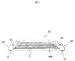
- FIG 2 is a perspective view illustrating a rack 200, according to an embodiment of the present invention.
- the rack 200 includes a rack section 201 to support food thereon.
- the rack 200 also includes support sections 202 to support the rack section 201 such that the rack section 201 is spaced apart from a bottom of a cooking chamber of a microwave oven by a desired distance when the rack 200 is disposed in the cooking chamber.
- the rack section 201 includes a plurality of hollow tubes 21 arranged in parallel while being uniformly spaced apart from one another.
- Each of the hollow tubes 21 is made of stainless steel and supported by the support sections 202 at opposite ends thereof, respectively.
- the support sections 202 are described with respect to Figures 2 and 3.
- FIG 3 is a perspective view illustrating an interior of a rack support section 202.
- the support section 202 is defined therein with a liquid reservoir 20 to contain a liquid.
- the liquid reservoir 20 communicates with all of the hollow tubes 21 so as to allow the liquid to flow through the hollow tubes 21.
- a liquid inlet 22a is formed at a top portion of each of the support sections 202 in order to put the liquid into the liquid reservoir 20 of the support section 202.
- a plug 22b is also provided to open and close the liquid inlet 22a.
- Support legs 23 are fixedly mounted to a bottom portion of each of the support sections 202 such that they extend downwardly from the support section 202.
- the configuration including the liquid reservoir 20 to contain the liquid, the liquid inlet 22a to put the liquid into the liquid reservoir 20, and the plug 22b to open and close the liquid inlet 22a is provided at each of the support sections 202, respectively, to support opposite ends of each of the hollow tubes 21.
- the configuration including the liquid reservoir 20, the liquid inlet 22a, and the plug 22b may be provided at only one support section 202 as shown in Figure 3, so that the present invention is still accomplished.
- the support sections 202 may be configured only to serve as a supporting unit to simply support the rack section 201.
- each of the hollow tubes 21 of the rack section 201 is configured in a form of a tube closed at opposite ends thereof while containing a liquid therein. Accordingly, the present invention may still be accomplished.
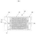
- FIG 4 is a perspective view of a rack for microwave ovens, according to another embodiment of the present invention.
- the rack section 201 includes a hollow net tube 205.
- the hollow net tube 205 is connected at opposite lateral ends thereof to respective support sections 202 by connecting tubes 24, so that the liquid received in the liquid reservoir of each of the support sections 202 flows through the hollow net tube 205.
- the plug 22b is separated from the liquid inlet 22a formed at the top portion of one of the support sections 202 to put a liquid into the liquid reservoir 20 of the support section 202 through the liquid inlet 22a.
- the liquid may be put into the liquid reservoir 20 in a sufficient amount without any liquid overflow.
- the liquid inlet 22a is closed by the plug 22b.
- Subsequent use of the rack 200 of the present invention may be carried out in the same manner as that of the conventional rack.
- a liquid other than water may be used, taking into consideration the burning point of the food being cooked. Sugar or salt-dissolved water may also be used.
- a selection of an appropriate liquid is made based on a temperature at which the rack section 201 becomes overheated.
- a preferable liquid is a liquid which allows the rack section 201 to be heated to a temperature at which the food is well heated without being burnt.
- Putting the liquid into the liquid reservoir 20 may be carried out by a user. Alternatively, liquid may be put into the liquid reservoir 20 at a manufacturing stage of the product. The liquid put in the liquid reservoir 20 may be replaced by another liquid in accordance with the user's desire.
- the rack section of the rack is made of iron, and plated with nickel or chromium, it may corrode at its portion contacting the water. As a result, life of the rack may be shortened.
- the rack section 201 of the rack 200 according to the present invention is made of stainless steel having no possibility of corrosion. The present invention may be accomplished even when a material other than stainless steel, for example, a material having a low possibility of corrosion, such as aluminum, or a material exhibiting no corrosion while having a high heat resistance, is used.
- FIG. 5 is a perspective view illustrating a microwave oven set 400, according to an embodiment of the present invention.
- the microwave oven set 400 comprises a cooking chamber 401, a rotatable heater 402 installed in the cooking chamber 401 and the rack 200 described in Figure 2.
- the heater 402 is disposed in a back side portion of the cooking chamber 401 when the heater 402 is not used, and is disposed at a lower portion of the cooking chamber 402 when the heater 402 is used.
- the rack 200 includes a rack section 201 to support food thereon and to be provided an upper portion of the heater 402 when the heater 402 is used.
- the rack 200 also includes support sections 202 to support the rack section 201 such that the rack section 201 is spaced apart from a bottom of the cooking chamber 401 of the microwave oven by a desired distance when the rack 200 is disposed in the cooking chamber 401.
Landscapes
- Physics & Mathematics (AREA)
- Electromagnetism (AREA)
- Engineering & Computer Science (AREA)
- Chemical & Material Sciences (AREA)
- Combustion & Propulsion (AREA)
- Mechanical Engineering (AREA)
- General Engineering & Computer Science (AREA)
- Electric Ovens (AREA)
- Cookers (AREA)
- Constitution Of High-Frequency Heating (AREA)
Abstract
Description
Claims (31)
- A rack (200) for a microwave oven including a rack section (201) to support food thereon, and support sections (202) to support the rack section, the rack being disposed in a cooking chamber defined in the microwave oven, the rack comprising:a plurality of hollow tubes (21) provided in the rack section, to contain a liquid therein.
- The rack according to claim 1, wherein, the plurality of hollow tubes (21) are arranged in parallel, and the support sections (202) support opposite ends of each of the hollow tubes, respectively, and at least one of the support sections is defined therein with a liquid reservoir (20) to contain the liquid which flows through the hollow tubes.
- A rack for a microwave oven including a rack section (201) to support food thereon, and support sections (202) to support the rack section, the rack being disposed in a cooking chamber defined in the microwave oven, the rack comprising:a hollow net tube (201) provided in the rack section, to contain a liquid therein.
- The rack according to claim 3, wherein the support sections (202) support opposite lateral ends of the hollow net tube, respectively, and at least one of the support sections is defined therein with a liquid reservoir (20) to contain the liquid which flows through the hollow net tube.
- The rack according to any preceding claim, wherein the hollow tubes or hollow net tube are made of a material free of corrosion.
- The rack according to claim 5, wherein the material free of corrosion is stainless steel.
- The rack according to any preceding claim, wherein at least one support section (202) includes a liquid inlet (22b) to put the liquid into a liquid reservoir (20), and a plug (22a) to open and close the liquid inlet.
- A microwave oven set equipped with the rack according to any preceding claim.
- A rack disposed in a cooking chamber of a microwave oven equipped with a heater, comprising:a rack section (201) to support food;support sections (202) to support the rack section so that the rack section is spaced apart from a bottom of the cooking chamber; anda plurality of hollow tubes (21) provided in the rack section, to contain a liquid therein.
- The rack according to claim 9, wherein the plurality of hollow tubes (21) are arranged in parallel, and receive the liquid from the support sections (202).
- The rack according to claim 9 or 10, wherein the support sections (202) support opposite ends of each of the hollow tubes, and are defined therein with a liquid reservoir (20) to contain the liquid which is received in and flows through the hollow tubes.
- The rack according to any of claims 9 to 11, wherein the support sections (202) comprise:a liquid inlet (22b) provided at a top portion thereof to put the liquid into the liquid reservoir of the support section;a plug (22a) to open and close the liquid inlet; andsupport legs (203) extended downward and fixedly mounted to a bottom portion thereof to support the support section.
- The rack according to any of claims 9 to 12, wherein at least one of the support sections (202) is defined therein with a liquid reservoir (20) to contain the liquid which flows through the hollow tubes.
- The rack according to any of claims 9 to 13, wherein the support sections (202) are provided at opposite ends of the hollow tubes (21) to support the rack section (201), and the hollow tubes are closed at the opposite ends to contain the liquid therein.
- The rack according to any of claims 9 to 14, wherein the hollow tubes (21) are made of stainless steel or aluminum.
- A rack disposable in a cooking chamber of a microwave oven equipped with a heater, comprising:a rack section (201) to support food;support sections (202) to support the rack section so that the rack section is spaced apart from a bottom of the cooking chamber; anda hollow net tube (201) provided in the rack section, to contain a liquid therein.
- The rack according to claim 16, wherein the support sections (202) support opposite ends of the hollow net tube, and are defined therein with a liquid reservoir to contain the liquid which is received in and flows through the hollow net tube.
- The rack according to claim 17, wherein the support sections (202) comprise:a liquid inlet (22b) provided at a top portion thereof to put the liquid in to the liquid reservoir of the support section;a plug (22a) to open and close the liquid inlet; andsupport legs (203) extended downward and fixedly mounted to a bottom portion thereof to support the support section.
- The rack according to any of claims 16 to 18, wherein at least one of the support sections (202) is defined therein with a liquid reservoir to contain the liquid which flows through the hollow net tube.
- The rack according to any of claims 16 to 19, wherein the support sections (202) are provided at opposite ends of the hollow net tube to support the rack section, and the hollow net tube is closed at the opposite ends to contain the liquid therein.
- The rack according to any of claims 16 to 20, wherein the hollow net tube is made of stainless steel or aluminum.
- A rack disposed in a cooking chamber of a microwave oven equipped with a heater, comprising:a rack section (201) to support food;support sections (202) to support the rack section so that the rack section is spaced apart from a bottom of the cooking chamber; anda hollow tubular portion (21) provided in the rack section, to contain a liquid therein.
- A microwave oven set, comprising:a cooking chamber;a heater installed in the cooking chamber;a rack (200) removably mounted in the cooking chamber, including a rack section (201) to support food over the heater, a support section (202) to support the rack section so that the rack section is spaced from a bottom of the cooking chamber, and a hollow tube (21) provided in the rack section, to contain a liquid therein.
- The microwave oven set according to claim 23, wherein the heater is disposed in a back side portion of the cooking chamber when the heater is not operated, and is disposed at a lower portion of the cooking chamber when it is operated.
- The microwave oven set according to claim 23 or 24, comprising a plurality of the hollow tubes (21).
- The microwave oven set according to claim 25, wherein the plurality of hollow tubes (21) are arranged in parallel, and receive the liquid from the support sections.
- The microwave oven set according to claim 25 or 26, wherein the support sections (202) support opposite ends of each of the hollow tubes, and are defined therein with a liquid reservoir (20) to contain the liquid which is received in and flows through the hollow tubes.
- The microwave oven set according to claim 27, wherein the support sections comprise:a liquid inlet (22b) provided at a top portion thereof to put the liquid into the liquid reservoir of the support section;a plug (22a) to open and close the liquid inlet, and support legs (203) which extended downward and are fixedly mounted to a bottom portion thereof to support the support section.
- The microwave oven set according to any of claims 23 to 28, wherein at least one of the support sections (202) is defined therein with a liquid reservoir (20) to contain the liquid which flows through the liquid which flows through the hollow tubes.
- The microwave oven set according to any of claims 23 to 29, wherein the support sections (202) are provided at opposite ends of the hollow tubes to support the rack section, and the hollow tubes are closed at the opposite ends to contain the liquid therein.
- The microwave oven set according to any of claims 23 to 30, wherein the hollow tube or tubes are made of stainless steel or aluminum.
Applications Claiming Priority (2)
| Application Number | Priority Date | Filing Date | Title |
|---|---|---|---|
| KR2002051317 | 2002-08-29 | ||
| KR1020020051317A KR20040021719A (en) | 2002-08-29 | 2002-08-29 | Rack for Microwave oven and Microwave oven |
Publications (2)
| Publication Number | Publication Date |
|---|---|
| EP1395086A2 true EP1395086A2 (en) | 2004-03-03 |
| EP1395086A3 EP1395086A3 (en) | 2005-04-06 |
Family
ID=31492907
Family Applications (1)
| Application Number | Title | Priority Date | Filing Date |
|---|---|---|---|
| EP02258974A Withdrawn EP1395086A3 (en) | 2002-08-29 | 2002-12-24 | Rack for microwave ovens, and microwave oven set equipped with the same |
Country Status (5)
| Country | Link |
|---|---|
| US (1) | US7009160B2 (en) |
| EP (1) | EP1395086A3 (en) |
| JP (1) | JP2004093104A (en) |
| KR (1) | KR20040021719A (en) |
| CN (1) | CN1231704C (en) |
Families Citing this family (4)
| Publication number | Priority date | Publication date | Assignee | Title |
|---|---|---|---|---|
| KR101544551B1 (en) * | 2009-05-04 | 2015-08-13 | 엘지전자 주식회사 | Cooking equipment |
| CN101907311A (en) * | 2009-06-05 | 2010-12-08 | 乐金电子(天津)电器有限公司 | Cavity bottom structure of cooking cavity of microwave oven |
| US20130119053A1 (en) * | 2011-11-16 | 2013-05-16 | Illinois Tool Works Inc. | Two tier elevated baking rack |
| US10085584B2 (en) | 2014-06-09 | 2018-10-02 | Whirlpool Corporation | Method of regulating temperature for sous vide cooking and apparatus therefor |
Family Cites Families (16)
| Publication number | Priority date | Publication date | Assignee | Title |
|---|---|---|---|---|
| JPH0237216A (en) * | 1988-07-26 | 1990-02-07 | Toshiba Corp | High frequency heating device |
| KR920003945Y1 (en) * | 1989-10-25 | 1992-06-13 | 권혁배 | Anti-glare device for headlights in automobiles |
| DE69111597T2 (en) * | 1991-06-05 | 1996-08-08 | Hidec Co Ltd | Re-frequency induction heater. |
| DE69309645T2 (en) * | 1992-12-21 | 1997-10-02 | Matsushita Electric Ind Co Ltd | Method and apparatus for heating with microwaves |
| KR960013288U (en) * | 1994-10-01 | 1996-05-17 | 서흥식 | Water-cooled grill |
| US5726428A (en) * | 1995-03-13 | 1998-03-10 | Christensen; Michael D. | Microwave oven shelf having multiple food supporting surface |
| KR960033461U (en) * | 1995-04-12 | 1996-11-19 | 권용익 | Grilled Water Circulation Grill |
| KR200144028Y1 (en) * | 1996-11-15 | 1999-06-15 | 전우기 | Charcoal Grill |
| US5842287A (en) * | 1997-04-08 | 1998-12-01 | Murphy; Willard J. | Towel warmer |
| JP2982759B2 (en) | 1997-08-12 | 1999-11-29 | 日本電気株式会社 | Method for manufacturing semiconductor device |
| US5938968A (en) * | 1997-08-28 | 1999-08-17 | Ogg; Starla | Retractable shelf assembly for a microwave oven |
| KR200204881Y1 (en) * | 1998-03-10 | 2001-01-15 | 이근진 | Oven Range Rack Cooling System |
| JP2001116263A (en) | 1999-10-19 | 2001-04-27 | Sanyo Electric Co Ltd | Microwave oven having heater |
| US6448542B2 (en) * | 1999-12-22 | 2002-09-10 | Nancy J. Wong | Microwave cooking rack |
| US6403937B1 (en) * | 2000-07-08 | 2002-06-11 | The Garland Group | Combination convection/microwave oven controller |
| US6617554B2 (en) * | 2001-09-28 | 2003-09-09 | Hearthware Home Products, Inc. | Counter-top electric cooker having a safety shut-off switch |
-
2002
- 2002-08-29 KR KR1020020051317A patent/KR20040021719A/en not_active Ceased
- 2002-12-24 EP EP02258974A patent/EP1395086A3/en not_active Withdrawn
- 2002-12-27 CN CNB021583617A patent/CN1231704C/en not_active Expired - Fee Related
-
2003
- 2003-01-28 US US10/351,996 patent/US7009160B2/en not_active Expired - Fee Related
- 2003-04-11 JP JP2003108242A patent/JP2004093104A/en active Pending
Also Published As
| Publication number | Publication date |
|---|---|
| KR20040021719A (en) | 2004-03-11 |
| JP2004093104A (en) | 2004-03-25 |
| EP1395086A3 (en) | 2005-04-06 |
| US20040040957A1 (en) | 2004-03-04 |
| US7009160B2 (en) | 2006-03-07 |
| CN1231704C (en) | 2005-12-14 |
| CN1479047A (en) | 2004-03-03 |
Similar Documents
| Publication | Publication Date | Title |
|---|---|---|
| US4384513A (en) | Apparatus for preparing pizza in a baking oven | |
| EP1674796A2 (en) | Electric oven | |
| EP2433529A2 (en) | Improved two-way heating cooker | |
| US11175048B2 (en) | Cooking appliance | |
| US6899019B2 (en) | Grilling apparatus | |
| KR20120005488U (en) | Frying pan assembly for roaster | |
| JP2004294050A (en) | Induction heating cooker | |
| EP1553805A2 (en) | Microwaveable cooking container and microwave oven | |
| CN115429127B (en) | Cooking equipment | |
| EP1395086A2 (en) | Rack for microwave ovens, and microwave oven set equipped with the same | |
| JP4512524B2 (en) | Cooker | |
| EP1444937A1 (en) | Grill unit and cooking apparatus with the same | |
| US4464406A (en) | Method for preparing pizza in a baking oven | |
| US6959704B2 (en) | Grill unit and cooking apparatus with the same | |
| JP4179252B2 (en) | Built-in induction heating cooker | |
| KR200179474Y1 (en) | Meat roast plate | |
| CN217365460U (en) | Cooking device and electric table top cooking device | |
| EP1444934A1 (en) | Grill unit and cooking apparatus with the same | |
| CN222487116U (en) | Cooking utensil | |
| KR200271938Y1 (en) | A brazier for cooking meat | |
| KR200464310Y1 (en) | Container for cooking | |
| KR200405803Y1 (en) | Eco-friendly multifunctional charcoal grill | |
| KR200291034Y1 (en) | Multiple heater in-equipped heating apparatus | |
| JP3069225U (en) | Food frying equipment | |
| JP2006329589A (en) | Cooker |
Legal Events
| Date | Code | Title | Description |
|---|---|---|---|
| PUAI | Public reference made under article 153(3) epc to a published international application that has entered the european phase |
Free format text: ORIGINAL CODE: 0009012 |
|
| 17P | Request for examination filed |
Effective date: 20030113 |
|
| AK | Designated contracting states |
Kind code of ref document: A2 Designated state(s): AT BE BG CH CY CZ DE DK EE ES FI FR GB GR IE IT LI LU MC NL PT SE SI SK TR |
|
| AX | Request for extension of the european patent |
Extension state: AL LT LV MK RO |
|
| PUAL | Search report despatched |
Free format text: ORIGINAL CODE: 0009013 |
|
| AK | Designated contracting states |
Kind code of ref document: A3 Designated state(s): AT BE BG CH CY CZ DE DK EE ES FI FR GB GR IE IT LI LU MC NL PT SE SI SK TR |
|
| AX | Request for extension of the european patent |
Extension state: AL LT LV MK RO |
|
| AKX | Designation fees paid |
Designated state(s): DE FR GB |
|
| STAA | Information on the status of an ep patent application or granted ep patent |
Free format text: STATUS: THE APPLICATION HAS BEEN WITHDRAWN |
|
| 18W | Application withdrawn |
Effective date: 20071128 |