EP1394995A1 - Redundate Netzwerkanordnung - Google Patents
Redundate Netzwerkanordnung Download PDFInfo
- Publication number
- EP1394995A1 EP1394995A1 EP02026538A EP02026538A EP1394995A1 EP 1394995 A1 EP1394995 A1 EP 1394995A1 EP 02026538 A EP02026538 A EP 02026538A EP 02026538 A EP02026538 A EP 02026538A EP 1394995 A1 EP1394995 A1 EP 1394995A1
- Authority
- EP
- European Patent Office
- Prior art keywords
- connection
- network
- host
- connections
- sub
- Prior art date
- Legal status (The legal status is an assumption and is not a legal conclusion. Google has not performed a legal analysis and makes no representation as to the accuracy of the status listed.)
- Granted
Links
- 238000004891 communication Methods 0.000 claims description 24
- 230000005540 biological transmission Effects 0.000 claims description 4
- RGNPBRKPHBKNKX-UHFFFAOYSA-N hexaflumuron Chemical compound C1=C(Cl)C(OC(F)(F)C(F)F)=C(Cl)C=C1NC(=O)NC(=O)C1=C(F)C=CC=C1F RGNPBRKPHBKNKX-UHFFFAOYSA-N 0.000 claims description 4
- 230000007704 transition Effects 0.000 claims description 3
- 238000012360 testing method Methods 0.000 description 20
- 238000000034 method Methods 0.000 description 8
- 238000012913 prioritisation Methods 0.000 description 8
- 238000010998 test method Methods 0.000 description 5
- 230000008901 benefit Effects 0.000 description 3
- 230000002457 bidirectional effect Effects 0.000 description 3
- 238000001514 detection method Methods 0.000 description 2
- 230000007257 malfunction Effects 0.000 description 2
- 230000003247 decreasing effect Effects 0.000 description 1
- 230000001419 dependent effect Effects 0.000 description 1
- 230000000694 effects Effects 0.000 description 1
- 238000005516 engineering process Methods 0.000 description 1
- 230000006870 function Effects 0.000 description 1
- 238000002955 isolation Methods 0.000 description 1
- 238000012986 modification Methods 0.000 description 1
- 230000004048 modification Effects 0.000 description 1
- 230000008569 process Effects 0.000 description 1
- 238000012545 processing Methods 0.000 description 1
- 230000002123 temporal effect Effects 0.000 description 1
Images

Classifications
-
- H—ELECTRICITY
- H04—ELECTRIC COMMUNICATION TECHNIQUE
- H04L—TRANSMISSION OF DIGITAL INFORMATION, e.g. TELEGRAPHIC COMMUNICATION
- H04L45/00—Routing or path finding of packets in data switching networks
-
- H—ELECTRICITY
- H04—ELECTRIC COMMUNICATION TECHNIQUE
- H04L—TRANSMISSION OF DIGITAL INFORMATION, e.g. TELEGRAPHIC COMMUNICATION
- H04L45/00—Routing or path finding of packets in data switching networks
- H04L45/22—Alternate routing
Definitions
- Disruptions to be considered include total failures and / or partial failures in individual elements of the communication system, e.g. Service platform, switches, routers, and Failure of the connections between the individual elements.
- LAN Local Area Network
- IP Internet Protocol
- a redundant network arrangement for connecting several Hosts with gateways appear in the European patent application 02019298 entitled “Redundant Network Arrangement” from described by the same applicant.
- a test procedure for network arrangements, especially for redundant network arrangements according to 02019298, is in the European patent application 02019297 entitled “Message Path Test Method in communication networks as well as network element "of the same Applicant described.
- Preferred embodiments are the subject of the dependent Expectations.
- An essential advantage of the invention is that when several devices host are connected to the second device G0 by the network arrangement N according to the invention, each device host has two redundant message paths to the second device G0 via two interfaces IF0, IF1. One of the message paths runs over the cross-connection Q 1 between the two redundant subnets, the other runs within a subnet.
- a second gateway G1 can advantageously be used. So it is avoided that the default gateway G0 fails to a Isolation of the entire network N leads.
- this advantageously results multiple message paths that facilitate communication between hosts and at least one of the gateways G0, G1 too in the event of disturbances to individual message paths due to disturbed Enable connections or disturbed mediating elements.
- Another advantage is that by means of the cross-connection (s) Q 1 between the sub-networks N 0 and N 1, several hosts can communicate with one another independently of the gateways, even when different interfaces of the hosts are active. For example, a first host with a first active interface, connected to the first subnet N 0 , with a second host with a second active interface, connected to the second subnet N 1 , can exchange messages via the cross-connection (s). This would not be possible without the cross connection according to the invention.
- the network arrangement according to the invention the administration of the entire network is made considerably easier, since many hosts from the centrally located gateway devices G0, G1 from only a single IP subnet can be reached. That minimizes the likelihood of incorrect administration and increases reliability.
- An advantageous test method for message paths in communication networks can be used for checking the message paths without modifications, since the wide area sections of the communication network include the frames or packets of the networks N 0 , N 1 or N 01 , N 02 , N 11 , N 12 to be transported Forward transparently and thus the end-to-end test of the paths between host and gateway (s) G0, G1 is not affected.
- Figure 1A shows the connection of a host device to a Gateway setup schematically over a redundant network represents.
- Figure 1B shows possible message paths in a redundant Network according to Figure 1A.
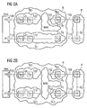
- Figure 2A shows schematically the redundant connection of a Host facility to a local gateway facility and by means of a long-distance connection to a remote gateway facility.
- Figure 2B shows schematically the redundant connection of a Host facility to remote gateway facilities using Wide area connection.
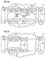
- Figure 3A shows schematically the redundant connection of a Host facility to a local gateway facility and via Ethernet over SONET connection to a remote one Gateway device.
- Figure 3B shows schematically the redundant connection of a Host facility to remote gateway facilities using Resilient packet ring.
- FIG. 1 shows a first host device.
- this first device can be, for example of the host facilities or service platforms mentioned at the beginning act.
- the first facility can be one any communication device with Layer 3 communication capabilities his.
- the Label host used for the first setup.
- the host is connected to a second one via a communication network N.
- Device G0 connected.
- This second facility can it is, for example, one of the gateways mentioned at the beginning act. However, the second facility can also any communication device with L3 communication capabilities his. In the following, the Label gateway used for the second facility.
- the communication network N is preferred Embodiment around a network, which with respect to layers 2 e.g. works according to the ethernet standard.
- Other networks and / or protocols are for transparent message transport usable between host and gateway.
- the network N is divided into two independent subnetworks N 0 , N 1 .
- this structure is implemented at the logical level, but is advantageously also carried out spatially in order to provide the greatest possible reliability.
- the subnet N 0 consists of a number of switching components or switches S 00 , S 01 , S 02 . Three switching components are shown, but this number is only an example and, from the point of view of this invention, is arbitrary, just as the structure of the subnetwork N 0 is arbitrary, which is only shown as a linear example.
- the switches S 00 , S 01 are connected to a connection L 01 , this connection being representative of a logical, bidirectional connection between the switches and can be physically formed by several connections, for example.
- the switches S 01 , S 02 are connected in the same way with a connection L 02 .
- the subnet N 1 consists of a number of switching components or switches S 10 , S 11 , S 12 . Three switching components are shown, but this number is only an example and, from the point of view of this invention, is arbitrary, just as the structure of the subnetwork N 0 is arbitrary, which is only shown as a linear example.
- the switches S 10 , S 11 are connected to a connection L 11 , this connection being representative of a logical, bidirectional connection between the switches and can be formed physically, for example, by a plurality of connections. In the same way, the switches S 11 , S 12 are connected with a connection L 12 .
- the subnet N 0 is connected to the host via a connection L 00 .
- the subnet N 1 is connected to the host via a connection L 10 .
- the host has two separate interfaces IF0, IF1, a first interface IF0 serving for the connection with N 0 and a second interface IF1 for the connection with N 1 .
- a connection L 03 serves to connect the subnet N 0 to the gateway G0.
- the subnet N 1 likewise has a connection to gateway G0 - not shown - and / or at least one cross-connection Q 1 to N 0 .
- This cross-connection advantageously takes place as close as possible to the transition from N 0 to gateway G0, ie, as shown in FIG. 1, for example between S 02 and S 12 .
- suitable protocols can be used to avoid L2 loops in connection with the present invention. It is understood that the cross-connection Q 1 can physically consist of several connections.
- a replacement gateway G1 is provided in addition to the gateway G0, for example in the event of the failure of the gateway G0 - shown in dashed lines.
- the gateways G0, G1 can also be connected by means of a cross connection Q 2 .
- a connection L 13 connects the subnet N 1 and gateway G1.
- the subnet N 0 also has a connection to gateway G1 - not shown.
- the gateways G0, G1 can be prioritized. by administering the gateways accordingly.
- connection from gateway G0 to subnet N 0 can be set up as a lower-cost route and the connection from gateway G1 to subnet N 1 as a higher-cost route.
- Prioritization is one way of ensuring, in the event of a fault in the cross-connection Q 1 , that both all hosts and the IP network IP always use the subnetwork (here: N 0 ) connected to the default gateway G0 for communication. This also secures all internal communication channels host to host.
- each host the (Default) gateway G0 can reach at least two ways and that a first host with an active interface IF0 and Standby interface IF1 with another host with standby interface IF0 and active interface IF1 - not shown - can communicate via message paths. Even if both gateways G0 and G1 malfunction, the hosts can exchange messages with one another via the cross connection.
- prioritization is not necessary in all cases, for example if the cross-connection Q 1 physically consists of several connections - not shown. In this case, prioritization is not necessary, since at least one additional connection is available if one of these connections fails.
- connections L 01 , L 02 and L 11 , L 12 shown in FIG. 1 between the mediating elements S 00 , S 01 , S 02 and S 10 , S 11 , S 12 and the cross connection Q 1 are conventionally implemented as local connections, whereby the networks N 0 and N 1 are pure local area networks LANs.
- Spatially spaced arrangements between the host device and gateway device (s) can, however, be realized by designing all or selected of the connections mentioned, for example with regard to layer 1, as long-distance connections.
- FIGS. 2A and 2B This is shown schematically in FIGS. 2A and 2B.
- a remote gateway device G0 is provided, which by means of a local area network N 01 consisting of switches S 00 and S 01 as well as connection L 01 , a schematically represented wide area network WAN and a second local area network N 02 consisting of the switch S 02 is connected to a host component. Furthermore, the cross-connection between the sub-networks N 02 and N 1 is also routed through the wide area network WAN. Based on the basic illustration from FIG. 1, the connections L 02 and Q 1 are implemented as long-distance connections in FIG. 2A; the optional second, local gateway G1 is connected by means of the local network N 1 .
- the host device is connected to two remote gateway devices G0, G1.
- the redundant connection is achieved on the one hand by a local network N 01 consisting of switches S 00 and S 01 as well as the connection L 01 and a local network N 02 consisting of switch S 02 , the local area networks N 01 and N 02 using a wide area network WAN are connected, and on the other hand by a local area network N 11 consisting of switches S 10 and S 11 and the connection L 11 and a local area network N 12 consisting of switch S 12 , the local area networks N 11 and N 12 by means of the wide area network WAN connected.
- the connections L 02 , L 12 and Q 1 are implemented as long-distance connections in FIG. 2A.
- FIG. 2 The exemplary embodiments shown in principle in FIG. 2 the connection of a host device to a gateway device (s) are now explained in more detail with reference to FIGS. 3A and 3B.
- FIG. 3A shows the case of a host device which is connected to a local gateway G1 and a remote gateway G0, based on the illustration from FIG. 2A.
- the host device is connected to the local gateway G1 by means of a local network (for example LAN) N 1 .
- a local network for example LAN
- N 1 a local network
- the connection L 02 and the cross connection Q 1 are formed in FIG. 3A by a wide area network (WAN).
- WAN wide area network
- the WAN is designed as an Ethernet-over-SONET ring.
- the SONET ring is preferably configured so that point-to-point connections are realized.
- FIG. 3B shows the case of a host device based on the illustration from FIG. 2B, which is connected to two remote gateways G0, G1, the gateway G1 being optional.
- the host device is connected to gateway G0 by means of a local network (e.g. LAN) N 0 and a resilient packet ring RPR according to IEEE 802.17 or a comparable WAN ring (e.g. Extreme Networks Ethernet Automatic Protection Switching EAPS or Cisco Resilient Packet Ring Technology ).
- Connection L 02 connects the sub-network N 0 to the RPR, the latter being shown by way of example as consisting of four Ethernet switches (preferably Gigabit Ethernet) E 1 , E 2 , E 3 , E 4 and a ring connection RPR.
- the ring RPR connects E 1 to E 2 , E 2 to E 3 , E 3 to E 4 and E 4 to E 1 each bidirectionally.
- connection between the WAN and the gateways takes place directly in FIG. 3B by means of the connections L 03 and L 13 , but, as shown in FIG. 2B, can also include further elements.
- the cross connection Q 1 is formed by the RPR. Viewed schematically, the RPR in FIG. 3B replaces the switches S 02 and S 12 and the cross connection Q 1 from FIG. 1.
- the host device is connected to the (optional) gateway G1 by means of a local network (eg LAN) N 1 and the RPR.
- Connection L 12 connects the subnet N 1 to the RPR.
- the network arrangement according to the invention can advantageously be used with a method for testing the message paths can be combined, which is briefly described below.
- the message paths are tested by the host sending special test IP datagrams to each gateway G0, G1 at very short time intervals, for example every 100 ms, via each interface or each interface IF0, IF1.
- the IP address of the respective own interface IF0 or IF1 is entered as the source IP address and the destination IP address.
- the gateway then reflects the test packet back to the sending interface IF0, IF1 of the host.
- the following table shows the IP and MAC addresses to be selected for testing the message paths Path1..Path4 path1 path2 path3 path4
- Destination MAC G0 G0 G1 G1 Source MAC IF 0 IF1 IF 0 IF1 Destination IP IF 0 IF1 IF 0 IF1 Source IP IF 0 IF1 IF 0 IF1 0 IF1
- MAC Media Access Control
- IP test messages An important advantage for IP test messages is that that only the "IP forwarding" function, based on the high performance Interface cards of the gateways implemented is for mirroring or returning the test messages to the sending instance is required. An overload situation in the gateway through the test procedure can therefore not occur because the gateway's processor at all is not involved in the processing of the test messages.
- test messages sent can be marked with sequence numbers or sequence numbers. These are included in the payload of the test messages entered. Not losing a configurable number necessarily consecutive test messages also used as a criterion for failure detection become, i.e. the message paths are numbered monitors the test messages.
- the counter for lost test messages can be designed so that a lost Test message incremented the counter by 1 and a configurable Number of test messages received without loss, e.g. 1000 the counter decreased by 1.
- humiliation can occur of the counter after a period of time during which no Test message loss has occurred. Reached the counter has a limit, the message path is considered to be disturbed scored.
- the host sends a "gratuitous ARP", i.e. an ARP Request for your own IP address.
- ARP Request for your own IP address.
- the ARP broadcast makes the ARP caches of everyone connected hosts and gateways with the MAC / IP address relation updated.
- the switchover takes place, for example on the replacement message paths mentioned, which according to their Prioritization can be selected.
- connection-oriented Protocols can be used for example for the host gateway connection be used. Will be interrupted by the protocol of the connection can be switched to a redundant transmission path can be initiated. example for such protocols are Real Time Protocol RTP or Stream Control Transmission Protocol SCTP.
Landscapes
- Engineering & Computer Science (AREA)
- Computer Networks & Wireless Communication (AREA)
- Signal Processing (AREA)
- Data Exchanges In Wide-Area Networks (AREA)
- Small-Scale Networks (AREA)
- Semiconductor Lasers (AREA)
- Microwave Amplifiers (AREA)
- Optical Communication System (AREA)
- Mobile Radio Communication Systems (AREA)
- Alarm Systems (AREA)
Abstract
Description
- bestehend aus einem ersten Teilnetz N0 und zumindest einem zweiten Teilnetz N1,
- wobei das erste Teilnetz (N0) aus ersten vermittelnden Elementen S00, S01, S02 besteht und wobei das zweite Teilnetz N1 aus zweiten vermittelnden Elementen S10, S11, S12 besteht und
- wobei das erste und das zweite Teilnetz unabhängig voneinander aufgebaut sind,
- mit zumindest einer Querverbindung Q1 zwischen den Teilnetzen N0, N1 und
- mit zumindest einer ersten Verbindung L00 zwischen dem ersten Teilnetz und einer ersten Schnittstelle IF0 der ersten Einrichtung Host und zumindest einer zweiten Verbindung L10 zwischen dem zweiten Teilnetz und einer zweiten Schnittstelle IF1 der ersten Einrichtung Host und mit zumindest einer dritten Verbindung L03 zwischen dem ersten Teilnetz und der zweiten Einrichtung G0,
- wobei Verbindungen L01, L02 zwischen den ersten vermittelnden Elementen S00, S01, S02 und/oder Verbindungen L11, L12 zwischen den zweiten vermittelnden Elementen S10, S11, S12 und/oder die Querverbindung(en) Q1 als Weitverkehrsverbindungen WAN ausgebildet sind.
| Pfad1 | Pfad2 | Pfad3 | Pfad4 | |
| Destination-MAC | G0 | G0 | G1 | G1 |
| Source-MAC | IF0 | IF1 | IF0 | IF1 |
| Destination-IP | IF0 | IF1 | IF0 | IF1 |
| Source-IP | IF0 | IF1 | IF0 | IF1 |
Claims (7)
- Netzwerkanordnung für ein Kommunikationsnetz (N), welches eine erste Einrichtung (Host) und eine zweite Einrichtung (G0) verbindet,bestehend aus einem ersten Teilnetz (N0) und zumindest einem zweiten Teilnetz (N1),wobei das erste Teilnetz (N0) aus ersten vermittelnden Elementen (S00, S01, S02) besteht und wobei das zweite Teilnetz (N1) aus zweiten vermittelnden Elementen (S10, S11, S12) besteht undwobei das erste und das zweite Teilnetz unabhängig voneinander aufgebaut sind,mit zumindest einer Querverbindung (Q1) zwischen den Teilnetzen (N0, N1) undmit zumindest einer ersten Verbindung (L00) zwischen dem ersten Teilnetz und einer ersten Schnittstelle (IF0) der ersten Einrichtung (Host) und zumindest einer zweiten Verbindung (L10) zwischen dem zweiten Teilnetz und einer zweiten Schnittstelle (IF1) der ersten Einrichtung (Host) und mit zumindest einer dritten Verbindung (L03) zwischen dem ersten Teilnetz und der zweiten Einrichtung (G0),wobei Verbindungen (L01, L02) zwischen den ersten vermittelnden Elementen (S00, S01, S02) und/oder Verbindungen (L11, L12) zwischen den zweiten vermittelnden Elementen (S10, S11, S12) und/oder die Querverbindung(en) (Q1) als Weitverkehrsverbindungen (WAN) ausgebildet sind.
- Netzwerkanordnung nach Anspruch 1,
dadurch gekennzeichnet, daß zumindest eine der Querverbindungen (Q1) unmittelbar am Übergang des Kommunikationsnetzes (N) zur zweiten Einrichtung (G0) angeordnet ist. - Netzwerkanordnung nach einem der Ansprüche 1 oder 2, mit zumindest einer vierten Verbindung (L13) zwischen dem ersten Teilnetz und einer der zweiten Einrichtung (G0) gleichartigen dritten Einrichtung (G1).
- Netzwerkanordnung nach einem der Ansprüche 1 bis 3,
dadurch gekennzeichnet, daß die Kommunikation zwischen der ersten und der zweiten und/oder dritten Einrichtung mittels Nachrichten einer ersten Protokollschicht erfolgt, deren Übertragung im Kommunikationsnetz (N) mittels einer der ersten Protokollschicht untergeordneten zweiten Protokollschicht erfolgt. - Netzwerkanordnung nach Anspruch 4,
dadurch gekennzeichnet, daß die erste Protokollschicht durch das Internet Protocol IP gebildet wird und die zweite Protokollschicht durch ein Protokoll eines Local Area Network LAN gebildet wird. - Netzwerkanordnung nach Anspruch 5,
dadurch gekennzeichnet, daß Weitverkehrsverbindung(en) (WAN) als Ethernet over SONET Verbindungen ausgeführt sind. - Netzwerkanordnung nach Anspruch 5,
dadurch gekennzeichnet, daß Weitverkehrsverbindung(en) (WAN) als Resilient Packet Ring RPR ausgeführt sind.
Priority Applications (1)
| Application Number | Priority Date | Filing Date | Title |
|---|---|---|---|
| EP02026538A EP1394995B1 (de) | 2002-08-28 | 2002-11-27 | Redundate Netzwerkanordnung |
Applications Claiming Priority (5)
| Application Number | Priority Date | Filing Date | Title |
|---|---|---|---|
| EP02019298 | 2002-08-28 | ||
| EP02019297A EP1394985A1 (de) | 2002-08-28 | 2002-08-28 | Testverfahren für Nachrichtenpfade in Kommunikationsnetzen sowie Netzelement |
| EP02019297 | 2002-08-28 | ||
| EP02019298A EP1394987A1 (de) | 2002-08-28 | 2002-08-28 | Redundante Netzwerkanordnung |
| EP02026538A EP1394995B1 (de) | 2002-08-28 | 2002-11-27 | Redundate Netzwerkanordnung |
Publications (2)
| Publication Number | Publication Date |
|---|---|
| EP1394995A1 true EP1394995A1 (de) | 2004-03-03 |
| EP1394995B1 EP1394995B1 (de) | 2009-02-11 |
Family
ID=40365560
Family Applications (1)
| Application Number | Title | Priority Date | Filing Date |
|---|---|---|---|
| EP02026538A Expired - Lifetime EP1394995B1 (de) | 2002-08-28 | 2002-11-27 | Redundate Netzwerkanordnung |
Country Status (4)
| Country | Link |
|---|---|
| EP (1) | EP1394995B1 (de) |
| AT (1) | ATE422767T1 (de) |
| DE (1) | DE50213270D1 (de) |
| ES (1) | ES2322241T3 (de) |
Families Citing this family (1)
| Publication number | Priority date | Publication date | Assignee | Title |
|---|---|---|---|---|
| DE102013110784B4 (de) * | 2012-10-05 | 2021-03-18 | Zte (Usa) Inc. | Dienstsensibles flexibles ipowdm-netz und betriebsverfahren |
Citations (3)
| Publication number | Priority date | Publication date | Assignee | Title |
|---|---|---|---|---|
| US5406549A (en) * | 1993-10-22 | 1995-04-11 | At&T Corp. | Ring interworking between path-switched ring transmission systems |
| EP0924901A2 (de) * | 1997-12-22 | 1999-06-23 | Nortel Networks Corporation | Gigabit-Ethernet Schnittstelle für ein synchrones Netz (SONET) |
| EP1168714A2 (de) * | 2000-06-27 | 2002-01-02 | Rockwell Electronic Commerce Corporation, Corporation of the State of Delaware | Packetnetzwerk mit redundanten Kanälen |
-
2002
- 2002-11-27 AT AT02026538T patent/ATE422767T1/de not_active IP Right Cessation
- 2002-11-27 ES ES02026538T patent/ES2322241T3/es not_active Expired - Lifetime
- 2002-11-27 DE DE50213270T patent/DE50213270D1/de not_active Expired - Lifetime
- 2002-11-27 EP EP02026538A patent/EP1394995B1/de not_active Expired - Lifetime
Patent Citations (3)
| Publication number | Priority date | Publication date | Assignee | Title |
|---|---|---|---|---|
| US5406549A (en) * | 1993-10-22 | 1995-04-11 | At&T Corp. | Ring interworking between path-switched ring transmission systems |
| EP0924901A2 (de) * | 1997-12-22 | 1999-06-23 | Nortel Networks Corporation | Gigabit-Ethernet Schnittstelle für ein synchrones Netz (SONET) |
| EP1168714A2 (de) * | 2000-06-27 | 2002-01-02 | Rockwell Electronic Commerce Corporation, Corporation of the State of Delaware | Packetnetzwerk mit redundanten Kanälen |
Non-Patent Citations (1)
| Title |
|---|
| JUNGLOON LEE ET AL: "Point to point label switching protocol for optical access networks", TENCON 2001. PROCEEDINGS OF IEEE REGION 10 INTERNATIONAL CONFERENCE ONELCTRICAL AND ELECTRONIC TECHNOLOGY. SINGAPORE, AUG. 19 - 22, 2001, IEEE REGION 10 ANNUAL CONFERENCE, NEW YORK, NY: IEEE, US, vol. 1 OF 2, 19 August 2001 (2001-08-19), pages 257 - 260, XP010556244, ISBN: 0-7803-7101-1 * |
Also Published As
| Publication number | Publication date |
|---|---|
| DE50213270D1 (de) | 2009-03-26 |
| ES2322241T3 (es) | 2009-06-18 |
| ATE422767T1 (de) | 2009-02-15 |
| EP1394995B1 (de) | 2009-02-11 |
Similar Documents
| Publication | Publication Date | Title |
|---|---|---|
| EP1532771B1 (de) | Testverfahren f r nachrichtenpfade in kommunikationsnetzen s owie netzelement | |
| EP2688249B1 (de) | Verfahren zur Nachrichtenübermittlung in einem redundant betreibbaren industriellen Kommunikationsnetz und Kommunikationsgerät für ein redundant betreibbares industrielles Kommunikationsnetz | |
| EP2070256B1 (de) | Verfahren zum rekonfigurieren eines kommunikationsnetzwerks | |
| EP2676409B1 (de) | Schleifen von mpls pfaden auf weiterleitungsebene für verbindungslose mpls netze | |
| EP1062787B1 (de) | Lokales netzwerk, insbesondere ethernet-netzwerk, mit redundanzeigenschaften sowie redundanzmanager | |
| DE60109177T2 (de) | Weiterleitung von IP Paketen für Leitweglenkung-Protokolen | |
| DE102007015539B4 (de) | Verfahren zum Rekonfigurieren eines Kommunikationsnetzwerks | |
| EP1100230B1 (de) | Datenübertragungssystem für Luftfahrzeuge | |
| DE112008002665T5 (de) | Bereitstellen einer Abstraktionsschicht in einem Clusterswitch, der mehrere Switches hat | |
| EP2693700A1 (de) | Verfahren zur Nachrichtenübermittlung in einem redundant betreibbaren industriellen Kommunikationsnetz und Kommunikationsgerät für ein redundant betreibbares industrielles Kommunikationsnetz | |
| EP2680503B1 (de) | Kommunikationsgerät für ein redundant betreibbares industrielles kommunikationsnetz und verfahren zum betrieb eines kommunikationsgeräts | |
| DE102022206121A1 (de) | Deadlock-freies lokales umleiten zur behandlung mehrerer lokaler verbindungsausfälle in hierarchischen netztopologien | |
| EP2130331B1 (de) | Verfahren zum rekonfigurieren eines kommunikationsnetzwerks | |
| EP2704370B1 (de) | Verfahren zur Nachrichtenübermittlung in einem redundant betreibbaren industriellen Kommunikationsnetz und Kommunikationsgerät für ein redundant betreibbares industrielles Kommunikationsnetz | |
| EP2043306A1 (de) | Verfahren zur Organisation von Netzknoten in einem paketorientierten Netzwerk | |
| EP1566039A1 (de) | Verfahren zur umleitung von datenpaketen bei lokal erkannten linkausfällen | |
| WO2020109015A1 (de) | Datenübertragungsverfahren und automatisierungskommunikationsnetzwerk | |
| EP2670078A1 (de) | Kommunikationsgerät für ein redundant betreibbares industrielles Kommunikationsnetz und Verfahren zum Betrieb eines Kommunikationsgeräts | |
| EP1514435B1 (de) | Ausfallsichere Anbindung eines Netzelementes an ein Kommunikationsnetz	 | |
| EP1394995B1 (de) | Redundate Netzwerkanordnung | |
| DE60200692T2 (de) | Wegeleitsystem zur Sicherstellung der Kontinuität der Interfacedienste zu den assoziierten Nachbarnetzen | |
| WO2006077173A1 (de) | Verfahren zur bestimmung der weiterleitungsrichtung von ethernet-frames | |
| EP1803261B1 (de) | Verfahren zur fehlererkennung in einem paketbasierten nachrichtenverteilsystem | |
| EP1394987A1 (de) | Redundante Netzwerkanordnung | |
| EP2750310A1 (de) | Verfahren zur Synchronisierung lokaler Uhren in einem Kommunikationsnetz eines industriellen Automatisierungssystems und Netzinfrastrukturgerät |
Legal Events
| Date | Code | Title | Description |
|---|---|---|---|
| PUAI | Public reference made under article 153(3) epc to a published international application that has entered the european phase |
Free format text: ORIGINAL CODE: 0009012 |
|
| AK | Designated contracting states |
Kind code of ref document: A1 Designated state(s): AT BE BG CH CY CZ DE DK EE ES FI FR GB GR IE IT LI LU MC NL PT SE SK TR |
|
| AX | Request for extension of the european patent |
Extension state: AL LT LV MK RO SI |
|
| 17P | Request for examination filed |
Effective date: 20040322 |
|
| AKX | Designation fees paid |
Designated state(s): AT DE ES FR |
|
| 17Q | First examination report despatched |
Effective date: 20070523 |
|
| RAP1 | Party data changed (applicant data changed or rights of an application transferred) |
Owner name: NOKIA SIEMENS NETWORKS GMBH & CO. KG |
|
| RAP3 | Party data changed (applicant data changed or rights of an application transferred) |
Owner name: NOKIA SIEMENS NETWORKS S.P.A. |
|
| RAP3 | Party data changed (applicant data changed or rights of an application transferred) |
Owner name: NOKIA SIEMENS NETWORKS GMBH & CO. KG |
|
| GRAP | Despatch of communication of intention to grant a patent |
Free format text: ORIGINAL CODE: EPIDOSNIGR1 |
|
| GRAS | Grant fee paid |
Free format text: ORIGINAL CODE: EPIDOSNIGR3 |
|
| GRAA | (expected) grant |
Free format text: ORIGINAL CODE: 0009210 |
|
| AK | Designated contracting states |
Kind code of ref document: B1 Designated state(s): AT DE ES FR |
|
| REF | Corresponds to: |
Ref document number: 50213270 Country of ref document: DE Date of ref document: 20090326 Kind code of ref document: P |
|
| REG | Reference to a national code |
Ref country code: ES Ref legal event code: FG2A Ref document number: 2322241 Country of ref document: ES Kind code of ref document: T3 |
|
| PLBE | No opposition filed within time limit |
Free format text: ORIGINAL CODE: 0009261 |
|
| STAA | Information on the status of an ep patent application or granted ep patent |
Free format text: STATUS: NO OPPOSITION FILED WITHIN TIME LIMIT |
|
| 26N | No opposition filed |
Effective date: 20091112 |
|
| PG25 | Lapsed in a contracting state [announced via postgrant information from national office to epo] |
Ref country code: AT Free format text: LAPSE BECAUSE OF NON-PAYMENT OF DUE FEES Effective date: 20091127 |
|
| PGFP | Annual fee paid to national office [announced via postgrant information from national office to epo] |
Ref country code: FR Payment date: 20131120 Year of fee payment: 12 |
|
| PGFP | Annual fee paid to national office [announced via postgrant information from national office to epo] |
Ref country code: ES Payment date: 20131128 Year of fee payment: 12 |
|
| REG | Reference to a national code |
Ref country code: DE Ref legal event code: R081 Ref document number: 50213270 Country of ref document: DE Owner name: NOKIA SOLUTIONS AND NETWORKS GMBH & CO. KG, DE Free format text: FORMER OWNER: NOKIA SIEMENS NETWORKS GMBH & CO. KG, 81541 MUENCHEN, DE Effective date: 20140731 |
|
| REG | Reference to a national code |
Ref country code: ES Ref legal event code: PC2A Owner name: NOKIA SOLUTIONS AND NETWORKS GMBH & CO.KG Effective date: 20141121 |
|
| REG | Reference to a national code |
Ref country code: FR Ref legal event code: CD Owner name: NOKIA SOLUTIONS AND NETWORKS GMBH & CO.KG, DE Effective date: 20150211 |
|
| REG | Reference to a national code |
Ref country code: FR Ref legal event code: ST Effective date: 20150731 |
|
| PG25 | Lapsed in a contracting state [announced via postgrant information from national office to epo] |
Ref country code: FR Free format text: LAPSE BECAUSE OF NON-PAYMENT OF DUE FEES Effective date: 20141201 |
|
| REG | Reference to a national code |
Ref country code: ES Ref legal event code: FD2A Effective date: 20151229 |
|
| PG25 | Lapsed in a contracting state [announced via postgrant information from national office to epo] |
Ref country code: ES Free format text: LAPSE BECAUSE OF NON-PAYMENT OF DUE FEES Effective date: 20141128 |
|
| PGFP | Annual fee paid to national office [announced via postgrant information from national office to epo] |
Ref country code: DE Payment date: 20181120 Year of fee payment: 17 |
|
| REG | Reference to a national code |
Ref country code: DE Ref legal event code: R119 Ref document number: 50213270 Country of ref document: DE |
|
| PG25 | Lapsed in a contracting state [announced via postgrant information from national office to epo] |
Ref country code: DE Free format text: LAPSE BECAUSE OF NON-PAYMENT OF DUE FEES Effective date: 20200603 |