The present application claims priority to prior Japanese patent
application JP 2002-252351, the disclosure of which is incorporated herein by
reference.
Background of the Invention:
The present invention relates to a magnetic loss material that is
excellent in magnetic loss characteristic at high frequencies, and further relates
to a method of producing the magnetic loss material.
In recent years, the spread of highly integrated semiconductor devices
operated at high speeds has been remarkable. As examples thereof, there
have been logic circuit elements or active elements, such as random access
memories (RAMs), read only memories (ROMs), microprocessor units (MPUs),
central processing units (CPUs), and image processor arithmetic logic units
(IPALUs). In these active elements, the calculation speeds or the signal
processing speeds have been rapidly increased. In this case, electrical signals
propagating in electronic circuits cause large fluctuation in voltage and current,
and therefore, inductive high-frequency radiated noise is liable to occur as
unwanted radiation.
On the other hand, reduction in weight, thickness and size of electronic
components and devices has also been rapidly advanced. Following it, the
degrees of integration of semiconductor devices and the mounting densities of
electronic components onto printed wiring boards have also been extremely
enhanced. Therefore, excessively integrated or mounted electronic elements
or signal lines are located very close to each other. ln combination with the
above-mentioned increase in signal processing speeds, the high-frequency
radiated noise become more liable to be induced.
In recent years, in such electronic integrated elements or wiring boards,
a countermeasure has been taken, for example, by inserting a lumped constant
component such as a decoupling capacitor in the transmissicn fine. However,
in the higher-speed electronic integrated elements or wiring toards, the
generated noise includes harmonic components so that a signal path tends to
behave as a distributed-constant circuit. As a consequence the conventional
noise countermeasure assuming a lumped constant circuit does not work
effectively.
Recently, the inventors have enabled to use a magnetic loss material
which exhibits a large magnetic loss in a high-frequency region. By disposing
the magnetic loss material in the neighborhood of an unwanted radiation source,
it is possible to effectively suppress unwanted radiation generated from a
semiconductor device, an electronic circuit, or the like, through suppressing a
conducted noise between noise source and radiation source. With respect to a
mechanism of unwanted radiation attenuation utilizing such a magnetic loss,
recent studies have shown that an equivalent resistance component is given to
the electronic circuit as the unwanted radiation source. Here, a magnitude of
the equivalent resistance component depends on a magnitude of an imaginary
part magnetic permeability µ", and a frequency region where a noise
suppression effect takes place depends on a frequency dispersion of the
imaginary part magnetic permeability µ". Therefore, in order to achieve greater
attenuation of unwanted radiation, a large value of the imaginary part magnetic
permeability µ" and the frequency dispersion of µ" matching v/ith the frequency
distribution of the unwanted radiation are required.
In most cases, however, the frequency distribution of unwanted radiation
actually generated in various electronic circuits spreads over a wide range and,
therefore, can not sufficiently be covered by a steep frequency dispersion of µ"
owing to magnetic resonance as observed in a typical magnetic material.
Further, the gentle magnetic permeability dispersion owing to an eddy current
loss can not provide a sufficient magnitude of µ" and, therefore, a large noise
suppression effect can not be expected.
Summary of the Invention:
It is therefore an object of the present invention to provide a magnetic
loss material that is effective against unwanted radiation from an active element,
an electronic circuit or the like that is operated at high speed.
It is another object of the present invention to provide a magnetic loss
material that can easily and effectively suppress unwanted radiation spreading
over a wide frequency band.
It is another object of the present invention to provide a magnetic loss
material that can effectively suppress a noise component without affecting a
signal component.
It is still another object of the present invention to provide a method of
producing the above-mentioned magnetic loss material.
The present inventors have made extensive and quantitative studies to
analyze a phenomenon that a resistance component is added to a transmission
line when a magnetic material with a magnetic loss is placed close to the
transmission line. As a result, it has been found out that a magnitude of a
suppression effect against conducted noise is substantially proportional to an
imaginary part permeance (µ"·δ), which is the product of an imaginary part
magnetic permeability µ" and a magnetization depth δ, and a frequency f.
Accordingly, the present inventors have conceived that, if a magnetic material
has a frequency dispersion profile of µ" that steeply rises and then gradually
decreases or that steeply rises and exhibits a large dispersion over a wide
frequency band, it is then possible to realize a lossy low-pass filter characteristic
and a band-eliminated filter characteristic that cause a sharp change in
equivalent resistance at a specific cut-off frequency. Thus, the present
invention has been made.
In order to evaluate the conducted noise suppression effect, it will be
helpful to consider the loss characteristic Ploss, as will later be described in detail.
The higher the frequency is, the loss characteristic decreases slowly in response
to reduction of the imaginary part magnetic permeability µ". In order to attain
the object of the present invention, the frequency dispersion of the imaginary
part magnetic permeability µ" must steeply rise. If the frequency dispersion of
the imaginary part magnetic permeability µ" decreases gently after the steep rise,
the loss can be maintained at a high level because of the above-mentioned loss
characteristic so that the excellent low-pass filter can be constituted. Moreover,
in case of the profile which steeply rises and rapidly decreases thereafter, the
excellent low-pass filter and the excellent band-eliminated filter can be obtained
by designing the profile exhibiting a large dispersion over a wide frequency
band.
In order to achieve the profile in which the dispersion of the imaginary
part magnetic permeability µ" rises steeply and decreases gently thereafter, the
spread of the dispersion must be asymmetrical. Specifically, the dispersion
must be narrow at a low frequency side and must be wide at a high-frequency
side. However, it is very difficult to realize such asymmetrical dispersion by a
single mechanism of permeability relaxation.
As an example of the dispersion asymmetrical on a frequency axis,
consideration will be made about a single sheet of magnetic thin film. In this
case, the gentle dispersion owing to eddy current circulation appears first (i.e., at
a low frequency side) and the steep dispersion owing to magnetic resonance
appears thereafter (i.e., at a high-frequency side). As a result, the profile in
which µ" gently rises and steeply decreases is obtained.
Thus, the profile typically observed is related to both of the eddy current
and the magnetic resonance and includes the dispersion owing to the eddy
current circulation at the low frequency side and the dispersion owing to the
magnetic resonance at the high-frequency side. Such typical profile is different
in required performance from the profile as a goal of the present invention, i.e.,
the profile which rises steeply and decreases gently thereafter. Therefore, the
typical profile is not desirable in noise protection which aims at effectively
suppressing a noise component without affecting a signal component in case
where the signal component and the noise component are close to each other.
In view of the foregoing, according to this invention, a magnetic loss
material is given two magnetic losses appearing in different frequency regions so
that a magnetic loss material exhibiting a dispersion profile of an imaginary part
magnetic permeability µ" that steeply rises and thereafter gently decreases or
that steeply rises and exhibits a large dispersion over a wide frequency band.
According to an aspect of the present invention, there is provided a
magnetic loss material comprising a soft magnetic powder and a binder binding
the particles of the powder to one another, the magnetic loss material having a
frequency dispersion profile of an imaginary part magnetic permeability (µ"),
wherein the frequency dispersion profile comprises at least two different
dispersion portions including a first dispersion portion (D1) at a relatively high-frequency
side and a second dispersion portion (D2) at a relatively low
frequency side, the imaginary part magnetic permeability (µ") having a first
maximum value (µ"max(D1)) that is the maximum within the first dispersion
portion (D1) and a second maximum value (µ"max (D2)) that is the maximum
within the second dispersion portion (D2), the second maximum value (µ"max
(D2)) being equal to or greater than the first maximum value (µ"max (D1)).
According to another aspect of the present invention, there is provided a
method of producing a magnetic loss material in which a frequency dispersion
profile of an imaginary part magnetic permeability (µ") has first and second
dispersion portions (D1 and D2) having mutually different dispersion frequency
regions, the second dispersion portion (D2) at a low-frequency side being a
dispersion owing to magnetic resonance, the method comprising preparing soft
magnetic powder of an indefinite shape having a thickness or a diameter which
is greater than a skin depth, grinding the soft magnetic powder to obtain hybrid
soft magnetic powder comprising a first particle group and a second particle
group each of which contains powder particles of an irregular shape or a flat
shape, the powder particles in the first particle group having a thickness or a
diameter which is greater than the skin depth, the powder particles in the second
particle group having a thickness or a diameter which is smaller than the skin
depth, mixing a binder including a high molecular compound into the hybrid soft
magnetic powder to obtain a mixture thereof, and molding the mixture.
Brief Description of the Drawings:
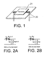
Fig. 1 is a diagram showing an example wherein a magnetic loss
material is disposed close to a transmission line through which unwanted high-frequency
current flows;
Figs. 2A and 2B are diagrams showing equivalent circuits of the
distributed constant line before and after the magnetic loss material is disposed,
respectively;
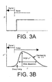
Fig. 3A is a diagram showing an ideal frequency characteristic of an
equivalent resistance component R necessary for noise separation;
Fig. 3B is a diagram showing an ideal frequency characteristic profile of
an imaginary part magnetic permeability µ" of the magnetic loss material;
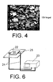
Fig. 4 is a scanning electron microscope photograph of a powder
sample;
Fig. 5 is a diagram showing a thickness distribution of the powder
sample and a skin depth δs of the powder sample;
Fig. 6 is a diagram showing an evaluation system for inspecting a
conducted noise suppression effect;
Fig. 7 is a µ-f characteristic diagram of a sample of embodiment 1 of the
present invention;
Fig. 8 is a µ-f characteristic diagram of a sample of embodiment 2 of the
present invention;
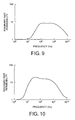
Fig. 9 is a µ-f characteristic diagram of a sample of embodiment 3 of the
present invention;
Fig. 10 is a µ-f characteristic diagram of a sample of embodiment 4 of
the present invention;
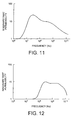
Fig. 11 is a µ-f characteristic diagram of a sample of embodiment 5 of
the present invention;
Fig. 12 is a µ-f characteristic diagram of a sample of embodiment 6 of
the present invention;
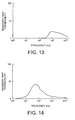
Fig. 13 is a µ-f characteristic diagram of a sample of embodiment 7 of
the present invention;
Fig. 14 is a µ-f characteristic diagram of a sample of comparative
example 1;
Fig. 15 is a µ-f characteristic diagram of a sample of comparative
example 2;
Fig. 16 is a µ-f characteristic diagram of a sample of comparative
example 3;
Fig. 17 is a diagram showing a frequency-dependent characteristic of
Ploss of the sample of embodiment 1;
Fig. 18 is a diagram showing a frequency-dependent characteristic of
Ploss of the sample of embodiment 2;
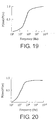
Fig. 19 is a diagram showing a frequency-dependent characteristic of
Ploss of the sample of embodiment 3;
Fig. 20 is a diagram showing a frequency-dependent characteristic of
Ploss of the sample of embodiment 4;
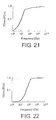
Fig. 21 is a diagram showing a frequency-dependent characteristic of
Ploss of the sample of embodiment 5;
Fig. 22 is a diagram showing a frequency-dependent characteristic of
Ploss of the sample of embodiment 6;
Fig. 23 is a diagram showing a frequency-dependent characteristic of
Ploss of the sample of embodiment 7;
Fig. 24 is a diagram showing a frequency-dependent characteristic of
Ploss of the sample of comparative example 1;
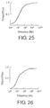
Fig. 25 is a diagram showing a frequency-dependent characteristic of
Ploss of the sample of comparative example 2; and
Fig. 26 is a diagram showing a frequency-dependent characteristic of
Ploss of the sample of comparative example 3.
Description of the Preferred Embodiments:
With reference to the drawing, description will be given about a magnetic
loss material and a method of producing the same according to a preferred
embodiment of the present invention.
Referring to Fig. 1, a magnetic loss material 21 as a test sheet is
disposed close to a transmission line 20 where electromagnetic noise conducts,
i.e. unwanted high-frequency current flows. In this event, the transmission line
20 and the magnetic loss material 21 are inductively coupled. As a result, the
transmission line 20 is given an equivalent resistance having frequency
selectivity so that an equivalent circuit of the transmission line shown in Fig. 2A
is changed to that shown in Fig. 2B. Here, the magnitude of the equivalent
resistance given to the transmission line 20 by the magnetic loss material 21
depends on the product (=µ"·f) of an imaginary part magnetic permeability µ'' of
the magnetic loss material 21 and a frequency f.
As shown in Fig. 3A, it is preferable that a resistance R given to the
transmission line is approximately equal to zero in a signal frequency region
(Signal) while the resistance R given to the transmission line is large in a noise
frequency region (Noise).
ln order to achieve the object of the present invention, the frequency
dispersion of the imaginary part magnetic permeability µ" must steeply rise.
Since, the higher the frequency is, the loss characteristic Ploss decreases slowly
in response to reduction of the imaginary part magnetic permeability µ", if the
frequency dispersion of the imaginary part magnetic permeability µ" decreases
gently after the steep rise, the loss can be maintained at a high level so that the
excellent low-pass filter can be constituted. Moreover, in case of the profile
which steeply rises and rapidly decreases thereafter, the excellent low-pass filter
and the excellent band-eliminated filter can be obtained by designing a profile
exhibiting the large dispersion over a wide frequency band.
Thus, as shown in Fig. 3B, an ideal dispersion profile of the imaginary
part magnetic permeability µ" rises steeply in response to the rise of frequency
and decreases gently thereafter. Moreover, although not illustrated in the
figure, large dispersion over a wide frequency band provides excellent
characteristics in case of the profile rising steeply and decreasing rapidly
thereafter.
In view of the foregoing, the frequency characteristic of the magnetic
loss material is given two different dispersion portions, i.e., first and second
dispersion portions D1 and D2 having mutually different frequency regions to
thereby achieve the dispersion profile of the imaginary part magnetic
permeability that steeply rises and thereafter gently decreases.
In order to obtain the two dispersion portions in the frequency
characteristic of the imaginary part magnetic permeability of the magnetic loss
material, several approaches are available as described hereinbelow. The
principles of those methods are disclosed in, for example, JP-A-H09-35927 and
J P-A-2001-21510.
As one approach, two magnetic powder groups different in frequency
dispersion region are mixed. As another approach, two magnetic powder
groups different in frequency dispersion region from each other are prepared
from one starting material by mechanical processing or the like. As a still
another approach, two frequency dispersion portions are achieved by a single
kind of powder.
Description will be made about a first method which is developed from
the above-mentioned approaches and which is intended to realize an ideal
dispersion profile having two dispersion portions in the frequency characteristic
of the imaginary part magnetic permeability. Those mechanisms which cause a
magnetic material to exhibit a magnetic loss include a mechanism based on
eddy current circulation and another mechanism based on magnetic resonance
(also called ferromagnetic resonance or natural resonance). The eddy current
produced in the magnetic material depends upon the thickness, the electric
resistance, the magnetic permeability, and the frequency. On the other hand,
the magnetic resonance greatly depends upon an anisotropic magnetic field Hk
of the magnetic material. Generally, the dispersion of the imaginary part
magnetic permeability owing to the magnetic resonance gives a steep change in
imaginary part magnetic permeability as compared with the dispersion owing to
the eddy current.
Therefore, dispersion of the imaginary part magnetic permeability which
rises steeply in response to the increase in frequency and thereafter decreases
gently can be realized if a magnetic material (magnetic powder) which exhibits
magnetic resonance at a relatively low frequency and another magnetic material
(magnetic powder) which causes permeability relaxation owing to the eddy
current at a relatively high frequency are mixed together at an appropriate ratio.
Furthermore, in order to obtain a dispersion profile of the imaginary part
magnetic permeability which rises steeply and exhibits a large dispersion over a
wide frequency band, magnetic materials (magnetic powder) whose dispersions
owing to the magnetic resonance are separated from each other by a desired
frequency bandwidth are mixed together at an appropriate ratio.
Now, a second method will be described. In order to cause the
magnetic resonance mentioned above, it is premised that no substantial eddy
current flows in a frequency range lower than a frequency at which the magnetic
resonance appears. Consideration will be made of powder with a single
common composition and a wide particle size distribution. If a skin depth (δs)
giving a criterion of eddy current circulation falls within a range of the particle
size distribution in a frequency region lower than the frequency at which the
magnetic resonance is expected, the powder group in which the particle size is
greater than the skin depth exhibits permeability relaxation owing to the eddy
current at a frequency lower than the frequency at which the magnetic
resonance is caused.
By utilizing the above-mentioned relationship between the size of the
magnetic powder and the skin depth, the dispersion of the imaginary part
magnetic permeability that steeply rises and thereafter gently decreases can be
obtained by the use of the powder having a single common composition.
Particularly, in case where starting material powder is magnetic metal powder
that is relatively brittle and when the powder is supplied to an agitated media mill
such as a ball mill, relatively large powder is partly broken off to become fine
powder. The fine powder is flattened under shearing stress of the media. As a
result, the fine powder is further reduced in thickness. Thus, a thickness
distribution of the powder is widened and may be separated into two thickness
groups.
In case where generation of the eddy current circulating inside the
powder is observed within a wide and dual distribution of the powder thickness,
the large powder contributes to gentle magnetic permeability dispersion owing to
the eddy current while the thin flat powder contributes to steep magnetic
permeability dispersion owing to the magnetic resonance. Therefore, one kind
of starting material powder with the single common composition provides the
imaginary part magnetic permeability having a dispersion profile comprising a
first dispersion portion D1 at the high-frequency side owing to the eddy current
and a second dispersion portion D2 at the low-frequency side owing to the
magnetic resonance.
Now, a third method will be described. Even if the powder has a
substantially uniform composition and a monotonous particle size distribution,
two magnetic resonances may possibly take place. Presumably, this
phenomenon is caused by surface magnetic anisotropy which will be observed
in the magnetic powder having a non-zero magnetostrictive constant when the
surface area of the powder reaches a certain extent. For example, the
magnetic powder having a non-zero magnetostrictive constant may be Fe3O4
(magnetite) or fine flat metal powder changed in composition under the shear
stress by a ball mill and, as a result, given a non-zero magnetostrictive constant.
Such phenomenon is described in detail by the present inventors in JP-A-2001-210510
and in S. Yoshida et al article, J. Appl. Phys., 85, 8, 4636 (1999).
With respect to the occurrence of the two magnetic resonances
presumably caused by the surface magnetic anisotropy, the surface area per
powder unit weight is a predominant factor. However, since the surface area
that causes the two resonances is also dependent upon other factors that bring
about the surface magnetic anisotropy, for example, the magnitude of a
magnetoelastic effect, i.e. the magnitude of a magnetostrictive constant, and a
magnitude of residual stress of.the powder, it is difficult to specify the value of the
surface area in question.
There is a tendency in which two resonances are generated in the soft
magnetic powder having a specific surface area of 0.3m2/g or more. However,
the above-mentioned powder provides no more than a dispersion profile
showing a gentle dispersion at a low frequency side and a steep dispersion at a
high-frequency side. By the recent studies, however, It has been found out that
the dispersion profile steeply rises at a low frequency side is obtained by a very
narrow range of the specific surface area and heat treatment of the powder.
The object of this invention can be achieved thereby.
In the foregoing, description has been given about the three methods for
obtaining such a dispersion profile in which the imaginary part magnetic
permeability steeply rises with the increase in frequency and thereafter gently
decreases or a dispersion profile in which the imaginary part magnetic
permeability steeply rises and exhibits a large dispersion over a wide frequency
band. Depending upon physical properties of magnetic powder to be used as a
raw material and a targeted dispersion frequency region of the imaginary part
magnetic permeability, the optimum method may be selected.
In each of the first to the third methods, it is necessary that the imaginary
part magnetic permeability µ" has a first maximum values µ"max (D1) that is the
maximum within the first dispersion portion D1 and a second maximum value
µ"max (D2) that is the maximum within the second dispersion portion D2 and the
second maximum value µ"max (D2) is equal to or greater than the first maximum
value µ"max (D1). Preferably, either of the relationships of Δfr" ≤D150 or Δfr" ≤D250
is established where Δfr" represents a difference between frequencies fr"max (D1)
and fr"max (D2). Wherein fr"max (D1) represents the frequency where the imaginary
part magnetic permeability µ" has a first maximum value µ"max (D1) and fr"max
(D2) represents the frequency where the imaginary part magnetic permeability
µ" has a second maximum value µ"max (D2), D150 represents a full width half
maximum of the first dispersion portion D1, and D250 represents a full width half
maximum of the second dispersion portion D2.
Now, description will be made in detail as regards several embodiments
of the present invention. In each of the embodiments, use is made of a soft
magnetic powder which includes first through (n+1)-th powders, where n is an
integer not smaller than one. The first and the (n+1 )-th powders are different
from each other in any one of the composition, the particle size, or the particle
shape and are mixed together into the soft magnetic powder.
At first, the first method will be described in conjunction with the case
where n = 1. Specifically, two kinds of soft magnetic powder are used.
Although the embodiment of n = 1 is described herein, the value of n may be 2
(embodiment using three kinds of soft magnetic powder), 3 (embodiment using
four kinds of soft magnetic powder), and so on as far as a desired characteristic
and a desired profile can be obtained.
(Embodiment 1)
First, the following soft magnetic powders a and b were prepared.
After annealing these two powders in an Ar gas atmosphere at 650°C for
three hours, a soft magnetic paste was prepared with a composition shown in
Table 1 and formed into a film by a doctor blade method. The film was then
subjected to hot press and thereafter cured at 85°C for 24 hours. Thus, a
magnetic loss material was obtained as a sample of the embodiment 1.
| component | mixing ratio |
| flat iron-aluminum-silicon alloy powder a | 60wt. parts |
| flat iron-aluminum-silicon alloy powder b | 40wt. parts |
| chlorinated polyethylene resin | 10wt. parts |
| solvent (toluene) | 50wt. parts |
| total | 160wt. parts |
At this time, the dispersion resulting from the powder a is D2. The
value of fr"maX (D2) is 26MHz and the full width half maximum D250 is 35MHz.
On the other hand, the dispersion resulting from the powder b is D1. The value
of fr"max (D1) is 161 MHz and the full width half maximum D150 is 320MHz.
These two powders satisfy the relationship given by fr"max(D1 ) > fr"max(D2) and
the relationship µ"max 1 < µ"max2, as seen from Fig. 7. Furthermore, since the
difference Δfr" = fr"max(D1) - fr"max(D2) is 135MHz, it will be understood that the
relationship Δfr" ≦ D150 is satisfied. In this embodiment, the relationship
shows Δfr" > D250. It is argued here on the supposition that the relationship Δ
fr" ≦ D150 is also not satisfied, i.e., the relationship shows Δ fr" > D150 and Δfr" >
D250. In this event, the µ-f characteristic has a valley between D1 and D2 and
the Ploss characteristic indicates that the noise is allowed to pass. In this
embodiment, the above-mentioned relationship Δfr" ≦ D150 is satisfied so that
the valley will not be produced. Therefore, a desired attenuation characteristic
is achieved.
(Embodiment 2)
Soft magnetic powders c and d were prepared.
These two powders were mixed to prepare a paste which was formed
into a film by a doctor blade method. The film was then subjected to hot
pressing and thereafter cured at 85°C for 24 hours. Thus, a magnetic loss
material was obtained as a sample of the embodiment 2.
| component | mixing ratio |
| teardrop-shaped nickel-iron alloy powder c | 20wt. parts |
| flat iron-aluminum-silicon alloy powder d | 80wt. parts |
| chlorinated polyethylene resin | 10wt. parts |
| solvent (toluene) | 50wt. parts |
| total | 160wt. parts |
The second method will be described.
(Embodiment 3)
Iron-aluminum-silicon alloy ingot (10wt% Si 6wt% Al - the balance Fe)
was prepared as starting material powder and subjected to stamp-mill grinding to
thereby obtain coarse powder of an irregular shape having an average particle
size of 40µm. The iron-aluminum-silicon coarse powder having an irregular
shape was supplied to a sand grinding mill together with n-hexane. The coarse
powder was ground for 15 hours to obtain a powder sample e. A scanning
electron microscope photograph of the powder sample e is shown in Fig. 4. By
the use of the powder e and with the ratio shown in Table 3, the magnetic loss
material was obtained as a sample of the third embodiment.
| component | mixing ratio |
| flat iron-aluminum-silicon alloy powder e | 100wt. parts |
| chlorinated polyethylene resin | 10wt. parts |
| solvent (toluene) | 50wt. parts |
| total | 160wt. parts |
Fig. 5 shows a distribution of a thickness of the above-mentioned
powder and the skin depth δs thereof after grinding for 15 hours. For the
thickness, the powder was sampled by random sampling and the thickness was
measured by an electron microscope photograph at several points to examine
the distribution. The skin depth δs is obtained by the following formula.
δs= ρπfµ [µm]
µ = µ0·µip = 4π×10-7×12 µeff
Herein, ρ represents an electric resistance [Ωm], f, a frequency [Hz], µeff,
magnetic permeability. At the frequency f = 100MHz, the powder e had the
magnetic permeability µeff = 17 and the electric resistance ρ = 9.0 x 10⁻⁷ Ω·m.
At this time, δs = 8.2 µm.
From Fig. 4 and 5, it is understood that the powder e has powder
thickness distribution comprising two groups including the powder group similar
in shape to the starting material coarse powder and the powder group of flat
powder particles and the skin depth δs exists within the range of the powder
thickness distribution.
The third method will be described.
(Embodiment 4)
Iron-aluminum-silicon alloy ingot (9.4wt% Si - 5.3wt% Al - the balance
Fe) containing a greater ratio of iron as compared with the Sendust composition
(9.6wt% Si - 5.4wt% Al - the balance Fe) and having a positive magnetostrictive
constant was prepared as starting material powder. The starting material
powder was subjected to stamp-mill grinding to thereby obtain coarse powder of
an irregular shape having an average particle size of 40µm. The resultant iron-aluminum-silicon
alloy coarse powder of an irregular shape was put into a sand
grinding mill together with n-hexane. The coarse powder was ground for 40
hours to obtain flat powder f having a B.E.T. specific surface area of 8.6m2/g.
After annealing the powder f in an Ar gas atmosphere at 650°C for three
hours, a soft magnetic paste was prepared with a composition shown in Table 4
and was formed into a film by a doctor blade method. The film was then
subjected to hot pressing and thereafter cured at 85°C for 24 hours. Thus, a
magnetic loss material was obtained as a sample of the embodiment 4.
| component | mixing ratio |
| flat iron-aluminum-silicon alloy powder f | 100wt. parts |
| chlorinated polyethylene resin | 10wt. parts |
| solvent (toluene) | 50wt. parts |
| total | 160wt. parts |
Similar stating material was put into a sand grinding mill together with n-hexane
and ground for 60 hours to obtain fine flat powder g having a B.E.T.
specific surface area of 1.53m2/g.
After annealing the powder g in an Ar gas atmosphere at 650°C for three
hours, a soft magnetic paste was prepared with a composition shown in Table 5
and formed into a film by a doctor blade method. The film was then subjected
to hot pressing and thereafter cured at 85°C for 24 hours. Thus, a magnetic
loss material was obtained as a sample of the embodiment 5.
| component | mixing ratio |
| flat iron-aluminum-silicon alloy powder g | 100wt. parts |
| chlorinated polyethylene resin | 10wt. parts |
| solvent (toluene) | 50wt. parts |
| total | 160wt. parts |
Nickel-iron alloy ingot (77wt% Ni - 23wt% Fe) containing a greater ratio
of iron than a Permalloy composition (80wt% Ni - 20wt% Fe) and having a
positive magnetostrictive constant was prepared as starting material powder and
subjected to stamp-mill grinding to thereby obtain coarse powder of an irregular
shape having an average particle size of 25µm. The nickel-iron alloy coarse
powder of an irregular shape was put into a sand grinding mill together with n-hexane
and ground for 8 hours to obtain fine flat powder h having a B.E.T.
specific surface area of 0.39m2/g.
By the use of the powder h, a soft magnetic paste was prepared with a
composition shown in Table 6 and formed into a film by a doctor blade method.
The film was then subjected to hot pressing and thereafter cured at 85°C for 24
hours. Thus, a magnetic loss material was obtained as a sample of the
embodiment 6.
| component | mixing ratio |
| flat nickel-iron alloy powder h | 100wt. parts |
| chlorinated polyethylene resin | 10wt. parts |
| solvent (toluene) | 50wt. parts |
| total | 160wt. parts |
By the use of Fe
3O
4 (Magnetite) powder i having a B.E.T. specific surface
area of 1.97m
2/g, a soft magnetic paste was prepared with a composition shown
in Table 7 and formed into a film by a doctor blade method. The film was then
subjected to hot pressing. Thus, a magnetic loss material was obtained as a
sample of the embodiment 7.
| component | mixing ratio |
| magnetite powder i | 100wt. parts |
| chlorinated polyethylene resin | 10wt. parts |
| solvent (toluene) | 50wt. parts |
| total | 160wt. parts |
Hereinbelow, three comparative examples will be described.
(Comparative Example 1)
Using flat iron-silicon-aluminum alloy powder j having a Sendust
composition (9.6wt% Si - 5.4wt% Al - the balance Fe) and a B.E.T. specific
surface area of 0.17m
2/g which is relatively large, a soft magnetic paste was
prepared with a composition shown in Table 8. In the manner similar to the
sample of the embodiment 1, a magnetic loss material was obtained as a sample
of comparative example 1.
| component | mixing ratio |
| flat iron-aluminum-silicon alloy powder j | 100wt. parts |
| chlorinated polyethylene resin | 10wt. parts |
| solvent (toluene) | 50wt. parts |
| total | 160wt. parts |
By the use of only one of the two soft magnetic powders used in the
sample of the embodiment 2, i.e., by the use of the teardrop-shaped powder a, a
soft magnetic paste was prepared with a composition shown in Table 9. In the
manner similar to the sample of the embodiment 1, a magnetic loss material was
obtained as a sample of comparative example 2.
| component | mixing ratio |
| teardrop-shaped nickel-iron alloy powder c | 100wt. parts |
| chlorinated polyethylene resin | 10wt. parts |
| solvent (mixture of cyclohexanone and toluene) | 50wt. parts |
| total | 160wt. parts |
Flat iron-aluminum-silicon alloy powder k having a Sendust composition
(9.6wt% Si - 5.4wt% Al - the balance Fe) and a B.E.T. specific surface area of
0.8m
2/g was obtained. The powder k was not subjected to annealing. Using
the powder k, a soft magnetic paste was prepared with a composition shown in
Table 10. In the manner similar to the sample of the embodiment 1, a magnetic
loss material was obtained as a sample of comparative example 3.
| component | mixing ratio |
| flat iron-aluminum-silicon alloy powder k | 100wt. parts |
| chlorinated polyethylene resin | 10wt. parts |
| solvent (toluene) | 50wt. parts |
| total | 160wt. parts |
As a result of comparison between the embodiment 4 and the comparative
example 3, it has been observed that these samples are similar in specific
surface areas to each other but are different in dispersion profile from each other.
That is, the dispersion profile of the sample subjected to annealing is different
from that of the sample without annealing (see Figs. 10 and 16). Presumably,
this is because if iron-silicon-aluminum alloy is annealed at a temperature higher
than 500°C, crystal growth of the DO3 structure is observed. In order to
sufficiently grow the DO3 structure, it is preferable that annealing is carried out at
650°C for about two hours. However, since high-temperature heat treatment is
accompanied with a problem of excessive oxidization or combustion, annealing
is preferably carried out in an inert gas atmosphere.
In order to evaluate the performance as a magnetic loss material with
respect to the samples of the foregoing embodiments, a frequency-dependent
characteristic of a magnetic permeability (µ-f characteristic) and a conducted
noise suppression effect were examined. For measurement of the µ-f
characteristic, toroidal-shaped samples of the magnetic loss material were used.
By measuring the impedance to insert each sample into a test fixture forming a
one-turn coil, an imaginary part magnetic permeability µ" was obtained over the
frequency range from 1 MHz to 10GHz.
On the other hand, evaluation of the conducted noise suppression effect
was performed using an evaluation system comprising a microstrip line 22 and a
network analyzer 23 as shown in Fig. 6. In the figure, the reference numeral 24
denotes a coaxial cable. A magnetic loss material 25 having a thickness of
2mm and a size of 20mm x 20mm was used as a test sheet and placed at the
center of the microstrip line 22 in close contact therewith. From transmission
characteristics S11 and S21 in the above-mentioned condition, a loss
characteristic Ploss was obtained using the following equation.
Ploss = 1- [(┌)2 + (T)2]
Herein, S11 = 20log|┌| and S21 = 20log|T|. rand T represent a voltage reflection
coefficient and a voltage transmission coefficient, respectively.
First, the µ"-f characteristics of the samples of the embodiments 1 to 7
are shown in Figs. 7 to 13. The µ''-f characteristics of the samples of the
comparative examples 1 to 3 are shown in Figs. 14 to 16. In the µ"-f
characteristics of the samples of the embodiments, each sample exhibited a
dispersion profile of an imaginary part magnetic permeability that steeply rises
and thereafter gently decreases due to manifestation of two imaginary part
magnetic permeability dispersions in frequency regions different from each other
or a frequency dispersion profile of an imaginary part magnetic permeability that
steeply rises and maintains a large value of the imaginary part permeability µ"
over a wide frequency band.
On the other hand, consideration will be made of the three samples of
the comparative examples. In the sample of the comparative example 1, steep
rising is achieved owing to the magnetic resonance but the imaginary part
magnetic permeability rapidly decreases after reaching its maximum value. In
the sample of the comparative example 2, relaxation dispersion is observed
presumably owing to eddy current circulation within the particles. Since rising
of the imaginary part magnetic permeability is gentle, this sample is not suitable
for suppression of electromagnetic noise that utilizes separation of frequency
regions. In the sample of the comparative example 3, two dispersion portions
are observed. However, rising is gentle presumably owing to eddy current
circulation. Therefore, this sample is inappropriate for separation of frequency
regions.
Using the samples of the embodiments and the comparative examples
having the imaginary part magnetic permeability dispersions described above, a
frequency-dependent characteristic (1 MHz to 10GHz) of a conducted noise
suppression effect Ploss was actually examined. Figs. 17 to 23 show frequency-dependent
characteristics of Ploss of the samples of the embodiments 1 to 7,
while Figs. 24 to 26 show frequency-dependent characteristics of Ploss of the
samples of the comparative examples 1 to 3.
From these figures, the effect of the present invention will clearly be
seen. Specifically, each of the samples of the embodiments exhibits a
frequency characteristic in which Ploss representing the degree of conducted
noise suppression steeply rises and is less attenuated thereafter, although a
frequency region where Ploss has large values is different among the samples.
On the other hand, in the sample of the comparative example 1, Ploss
steeply rises but greatly decreases after reaching its maximum value. In the
sample of the comparative example 2, the variation of Ploss is moderate.
Therefore, this sample is not suitable for separating signal and noise by
frequency region. In the sample of the comparative example 3, Ploss rises less
steeply and, in a certain frequency range higher than about 30MHz, exhibits a
gentle curve, as compared with the sample of the embodiment 4 which had a
similar B.E.T. specific surface area and which was subjected to heat treatment.
Thus, the embodiment 4 is superior.
Typically, a magnetic material that can be used for producing the soft
magnetic powder may be a soft magnetic metal material having a large value of
the high-frequency permeability, such as silicon steel, an iron-aluminum-silicon
alloy (Sendust), an iron-nickel alloy (Permalloy), or an amorphous alloy. The
soft magnetic powder may be obtained from the above-mentioned soft magnetic
material by grinding, drawing, tearing, atomization-granulation, or the like. As
desired, the obtained powder may be further processed into a flat shape by the
use of an agitated media mill such as a ball mill. Furthermore, the obtained
powder and the flattened powder may be annealed.
Various other soft magnetic materials are also available. For example,
it is possible to obtain a desired magnetic loss material by the use of an oxide
soft magnetic material, such as spinel ferrite, planar ferrite, hematite, magnetite,
or maghematite.
As a binder to be used as a secondary material for obtaining the
magnetic loss material, it is advantageous to use chlorinated polyethylene that
can achieve excellent flexibility and fire resistance, taking into account the use
thereof in the neighborhood of an electronic circuit. Without being limited
thereto, however, it is possible to use various organic binders, for example,
thermoplastic resin such as polyester resin, polyethylene resin, polyvinyl chloride
resin, polyvinyl butyral resin, polyurethane resin, cellulose resin, ABS resin,
nitrile-butadiene rubber, styrene-butadiene rubber, or silicone rubber, copolymer
thereof, and thermosetting resin such as epoxy resin, phenol resin, amide resin,
or imide resin.
No specific limitation is imposed upon a method of mixing and dispersing
the magnetic powder and the binder to obtain the magnetic loss material. With
reference to the physical properties of the binder to be used and ease of the
process, a suitable method may be selected.
The foregoing magnetic loss material has a frequency dispersion profile
of the imaginary part magnetic permeability µ" that steeply rises and thereafter
gradually decreases or a frequency dispersion of the imaginary part magnetic
permeability µ" that steeply rises and maintains a large imaginary part magnetic
permeability µ" over a wide frequency band. Therefore, Ploss as an index of a
conducted noise suppression effect has a frequency characteristic which steeply
rises and is less attenuated thereafter. Accordingly, by the use of the above-mentioned
magnetic loss material, it is possible to effectively attenuate a noise
component without adversely affecting a signal component. Therefore, the
above-mentioned magnetic loss material has an excellent effect of suppressing
the radiation of unwanted electromagnetic waves and is highly effective in
preventing noise in an electronic component, particularly, a high-speed active
element, a high-density printed wiring board, or the like.