EP1394731A2 - Memory Card Connector - Google Patents
Memory Card Connector Download PDFInfo
- Publication number
- EP1394731A2 EP1394731A2 EP03019859A EP03019859A EP1394731A2 EP 1394731 A2 EP1394731 A2 EP 1394731A2 EP 03019859 A EP03019859 A EP 03019859A EP 03019859 A EP03019859 A EP 03019859A EP 1394731 A2 EP1394731 A2 EP 1394731A2
- Authority
- EP
- European Patent Office
- Prior art keywords
- memory card
- catching portion
- slider
- card connector
- catch spring
- Prior art date
- Legal status (The legal status is an assumption and is not a legal conclusion. Google has not performed a legal analysis and makes no representation as to the accuracy of the status listed.)
- Granted
Links
Images




Classifications
-
- H—ELECTRICITY
- H01—ELECTRIC ELEMENTS
- H01R—ELECTRICALLY-CONDUCTIVE CONNECTIONS; STRUCTURAL ASSOCIATIONS OF A PLURALITY OF MUTUALLY-INSULATED ELECTRICAL CONNECTING ELEMENTS; COUPLING DEVICES; CURRENT COLLECTORS
- H01R13/00—Details of coupling devices of the kinds covered by groups H01R12/70 or H01R24/00 - H01R33/00
- H01R13/62—Means for facilitating engagement or disengagement of coupling parts or for holding them in engagement
- H01R13/629—Additional means for facilitating engagement or disengagement of coupling parts, e.g. aligning or guiding means, levers, gas pressure electrical locking indicators, manufacturing tolerances
-
- G—PHYSICS
- G06—COMPUTING OR CALCULATING; COUNTING
- G06K—GRAPHICAL DATA READING; PRESENTATION OF DATA; RECORD CARRIERS; HANDLING RECORD CARRIERS
- G06K13/00—Conveying record carriers from one station to another, e.g. from stack to punching mechanism
- G06K13/02—Conveying record carriers from one station to another, e.g. from stack to punching mechanism the record carrier having longitudinal dimension comparable with transverse dimension, e.g. punched card
- G06K13/06—Guiding cards; Checking correct operation of card-conveying mechanisms
- G06K13/067—Checking presence, absence, correct position, or moving status of cards
-
- G—PHYSICS
- G06—COMPUTING OR CALCULATING; COUNTING
- G06K—GRAPHICAL DATA READING; PRESENTATION OF DATA; RECORD CARRIERS; HANDLING RECORD CARRIERS
- G06K13/00—Conveying record carriers from one station to another, e.g. from stack to punching mechanism
- G06K13/02—Conveying record carriers from one station to another, e.g. from stack to punching mechanism the record carrier having longitudinal dimension comparable with transverse dimension, e.g. punched card
- G06K13/08—Feeding or discharging cards
-
- G—PHYSICS
- G06—COMPUTING OR CALCULATING; COUNTING
- G06K—GRAPHICAL DATA READING; PRESENTATION OF DATA; RECORD CARRIERS; HANDLING RECORD CARRIERS
- G06K13/00—Conveying record carriers from one station to another, e.g. from stack to punching mechanism
- G06K13/02—Conveying record carriers from one station to another, e.g. from stack to punching mechanism the record carrier having longitudinal dimension comparable with transverse dimension, e.g. punched card
- G06K13/08—Feeding or discharging cards
- G06K13/0806—Feeding or discharging cards using an arrangement for ejection of an inserted card
-
- G—PHYSICS
- G06—COMPUTING OR CALCULATING; COUNTING
- G06K—GRAPHICAL DATA READING; PRESENTATION OF DATA; RECORD CARRIERS; HANDLING RECORD CARRIERS
- G06K13/00—Conveying record carriers from one station to another, e.g. from stack to punching mechanism
- G06K13/02—Conveying record carriers from one station to another, e.g. from stack to punching mechanism the record carrier having longitudinal dimension comparable with transverse dimension, e.g. punched card
- G06K13/08—Feeding or discharging cards
- G06K13/085—Feeding or discharging cards using an arrangement for locking the inserted card
- G06K13/0856—Feeding or discharging cards using an arrangement for locking the inserted card the locking arrangement comprising a notch in the card and a complementary locking means in the card reading station
Definitions
- the present invention relates to an inserting and extracting mechanism of a memory card connector, and more particularly to the inserting and extracting mechanism of the memory card connector for preventing damage of the mechanism in case where the memory card is inserted in a wrong direction by mistake and in case where the memory card is extracted by mistake.
- Fig. 7 shows a memory card connector 1 in a state where a memory card 21 is inserted therein.
- the memory card connector 1 includes a base frame 2 made of resin, and a top cover 3 which is made of metal and engaged with the base frame 2 to form a box-like body.
- Fig. 8 shows the base frame 2 having a slider 4, and contact pins 5 which are arranged in a rear part (at a left side in Fig. 8) of the base frame 2 in parallel, according to an arrangement of terminals in the memory card 21.
- a slider guide 6 is formed near a left edge (at a lower side in Fig.
- a catch spring 8 attached to the slider 4 has a catching portion 8a in an arc shape which is formed by stamping, at its distal end. The catching portion 8a protrudes into an interior space of the memory card connector 1.
- Figs. 9 and 10 show the memory card 21, which has such a shape that its forward left end corner is diagonally cut away in order to restrict an inserting direction.
- the memory card 21 is provided with a groove 23 in a longitudinal direction behind a diagonal face 22 at the forward left end, and a recess 24 in a semicircular shape on a left side face.
- the slider 4 in the memory card connector 1 has such a shape as matching the diagonal face 22 and the groove 23 of the memory card 21.
- Fig. 11 shows the memory card 21 in a state inserted in the memory card connector 1. Contacts of the memory card 21 are in contact with the contact pins 5 of the memory card connector 1, while the catching portion 8a of the catch spring 8 is restricted from outward movement by a lock plate 3a provided on the top cover 3, and held in a state engaged with the recess 24 of the memory card 21.
- the memory card connector 1 is provided with a known slider lock mechanism which includes a heart-shaped groove cam formed on a back side face of the slider 4 and a lock pin provided on the base frame 2.
- the lock pin moves along the heart-shaped groove cam according to a longitudinal movement of the slider 4, and when the slider 4 has retreated to a locked position, the lock pin is engaged with a recess of the heart-shaped groove cam thereby to lock the slider 4 in the locked position.
- the memory card 21 is pushed into the depth, and the lock pin will be disengaged from the recess of the heart-shaped groove cam to unlock the slider 4. Then, the slider will move forward by means of the helical-compression spring, and the memory card 21 will be discharged.
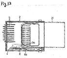
- the slider 4 retreats in a state where the catch spring 8 is pressed with a side face of the memory card 21 to be flexed outwardly as shown in Fig. 12, and the catching portion 8a of the catch spring 8 is abutted against the lock plate 3a of the top cover 3 to stop the slider 4.
- the catch spring 8 may drop from the slider 4, or the catching portion 8a may be bent and jammed between the memory card 21 and the lock plate 3a, and in some cases, the catch spring 8 may be broken.
- the memory card 21 will strike the contact pins 5, and the contact pins 5 may be broken in some cases.
- Another object of the present invention is to provide a memory card connector in which an accident of damaging the memory card connector in case where the memory card which is inserted into the memory card connector is pulled is prevented.
- a memory card connector comprising:
- the catching portion of the catch spring has a protruding portion.
- the lock plate is formed in a height so as to opposed to only the protruding portion of the catching portion.
- the protruding portion of the catching portion is rotated outside of the lock plate to move the slider for preventing the catching portion from striking the lock plate when the memory card is inserted in the memory card connector in an opposite direction.
- the catching portion of the catch spring will not strike the lock plate, and damage or deformation of the catch spring can be prevented.
- a recessed part is formed on an inner side face of the slider. The catching portion is moved into the recessed part when the protruding portion of the catching portion is rotated outside of the lock plate.
- the memory card connector further comprises:
- the catching portion moves outside of the inserting and extracting area of the memory card when the force greater than a predetermined force is applied to the catching portion in an extracting direction of the memory card in a state that the memory card is inserted to the contact position.
- the catching portion of the catch spring has a substantially V-shape formed by a rectilinear plane face.
- the catching portion is in a substantially V-shape, when the memory card is extracted, the catching portion will be smoothly removed from the recess of the memory card, and durability of the catch spring will be enhanced.
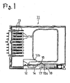
- Fig. 1 shows a base frame 11 of the memory card connector, in which arrangements of a slider 12 and contact pins 13 are the same as in the related memory card connector 1 illustrated in Fig. 8, but a catch spring 14 and a lock plate of a top cover which will be described below are different in shape.
- the base frame 11 is provided with a rib 11a surrounding the contact pins 13 so that the memory card may be abutted against the rib 11a in case where the memory card is inserted in an opposite direction, and insertion of the memory card may be hindered in front of the contact pins 13, and accordingly, damage of the contact pins 13 will be prevented.
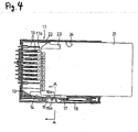
- Fig. 2 shows the memory card 21 in a state inserted in a proper direction.
- the catching portion 15 of the catch spring 14 is engaged with the recess 24 on the left side face of the memory card 21, in the same manner as in the related case, and the slider 12 is pushed in, along with the memory card 21, thereby to bring the contacts of the memory card 21 into contact with the contact pins 13 of the memory card connector.
- an enlarged part 15a at a distal end of the catching portion 15 is abutted against a lock plate 16a formed on a top cover 16 and hindered from outward movement.
- the catching portion 15 is held so as not to be released from the recess 24 of the memory card 21, and at the same time, the slider 12 is secured in a locked position by a known slider lock mechanism which includes a heart-shaped groove cam 17 formed on a side face of the slider 12 and a lock pin 18 attached to the base frame 11, as shown in Fig. 2, and thus, the memory card 21 will be properly inserted.
- a known slider lock mechanism which includes a heart-shaped groove cam 17 formed on a side face of the slider 12 and a lock pin 18 attached to the base frame 11, as shown in Fig. 2, and thus, the memory card 21 will be properly inserted.
- Fig. 3 is a view as seen from a line A-A in Fig. 2.
- the catch spring 14 has a stepped shape in an L-shape in which only an enlarged distal end part 15a of the catching portion 15 is formed higher.
- the lock plate 16a suspended from the top cover 16 is shorter as compared with the related case, and positioned at such a height that the lock plate 16a may be opposed to only the enlarged distal end part 15a and may not interfere with other parts except the enlarged distal end part 15a.
- a distance in a vertical direction between the lock plate 16a and an inner bottom face of the base frame 11 is larger than a height of the other parts of the catch spring 14 except the enlarged distal end part 15a.
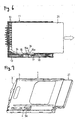
- the catching part 15 of the catch spring 14 is first pressed with the side face of the memory card 21 to be rotated outwardly, and the distal end part of the catching portion 15 retreats into a recessed part 12a of the slider 12, as shown in Fig. 5.
- the distal end part 15a of the catching portion 15 moves outside of the lock plate 16a without contacting the lock plate 16a as shown in Fig. 5, and the memory card 21 which is inserted in the opposite direction as shown in Fig. 6 will be blocked by an arm portion 12b of the slider 12 to stop at a halfway of the insertion of the memory card 21.
- the slider 12 moves forward and returns to the initial position as shown in Fig. 1, and the catch spring 14 too will be restored from the outwardly flexed state to the initial state.
- the memory card in the case where outward pressure is applied on an apex of the catching portion 15 of the catch spring 14 in the locked state as shown in Figs. 2 and 3.
- the catch spring 14 will be flexed outwardly between a secured point and the enlarged distal end part 15a making them as pivots, and can retreat into a recessed part 12a of the slider 12.
- Fig. 6 shows a state in which the memory card 21 which is inserted into the memory card connector is pulled in an extracting direction.
- the catching portion 15 of the catch spring 14 which is engaged with the recess on the side face of the memory card 21 will be flexed outwardly by extracting stress, and disengaged from the recess 24 of the memory card 21, allowing the memory card 21 to be extracted from the memory card connector. Therefore, different from the related inserting and extracting mechanism, the catch spring will not be bent, nor drop due to extraction of the memory card, or the slider 4 will not be pulled with force, without damaging the groove cam 17 and the lock pin 18 in the slider lock mechanism, and thus, damage of the memory card connector will be prevented.
- the catching portion 15 is in a substantially V-shape, having an inclined backward face (at a left side in the drawing) in a form of a rectilinear gentle slope which is different from the related shape having the face at an angle nearly vertical as shown in Fig. 8. Accordingly, when the memory card 21 is extracted, the catching portion 15 will be smoothly removed from the recess 24 of the memory card 21, and the extracting stress to be exerted on the catch spring 14 will be decreased, thereby enhancing durability of the catch spring.
Landscapes
- Physics & Mathematics (AREA)
- General Physics & Mathematics (AREA)
- Engineering & Computer Science (AREA)
- Theoretical Computer Science (AREA)
- Coupling Device And Connection With Printed Circuit (AREA)
- Details Of Connecting Devices For Male And Female Coupling (AREA)
Abstract
Description
Claims (7)
- A memory card connector, comprising:wherein the catching portion retreats outside of an inserting and extracting area of the memory card when a force greater than a predetermined force is applied to the catching portion.a slider, being slidable in a direction in which a memory card is inserted to and exerted from the memory card connector;a catch spring, mounted on the slider, and having a catching portion which is engaged with the memory card; anda lock plate, holding an engagement between the catching portion and the memory card when the memory card is inserted to a position of contacting with the memory card connector,
- The memory card connector as set forth in claim 1, wherein the catching portion of the catch spring has a protruding portion; and
wherein the lock plate is formed in a height so as to opposed to only the protruding portion of the catching portion. - The memory card connector as set forth in claim 2, wherein the protruding portion of the catching portion is rotated outside of the lock plate to move the slider for preventing the catching portion from striking the lock plate when the memory card is inserted in the memory card connector in an opposite direction.
- The memory card connector as set forth in claim 3, wherein a recessed part is formed on an inner side face of the slider; and
wherein the catching portion is retreated into the recessed part when the protruding portion of the catching portion is rotated outside of the lock plate. - The memory card connector as set forth in claim 1 further comprising:a contact pin, connecting the memory card when the memory card is inserted to the contact position; anda rib, formed around the contact pin for preventing an intrusion of the memory card when the memory card is inserted into the memory card connector in an opposite direction.
- The memory card connector as set forth in claim 1, wherein the catching portion retreats outside of the inserting and extracting area of the memory card when the force greater than a predetermined force is applied to the catching portion in an extracting direction of the memory card in a state that the memory card is inserted to the contact position.
- The memory card connector as set forth in claim 1, wherein the catching portion of the catch spring has a substantially V-shape formed by a rectilinear plane face.
Applications Claiming Priority (4)
| Application Number | Priority Date | Filing Date | Title |
|---|---|---|---|
| JP2002256196 | 2002-08-30 | ||
| JP2002256197 | 2002-08-30 | ||
| JP2002256197A JP2004095418A (en) | 2002-08-30 | 2002-08-30 | Memory card connector insertion / extraction mechanism |
| JP2002256196A JP2004095417A (en) | 2002-08-30 | 2002-08-30 | Memory card connector insertion / extraction mechanism |
Publications (3)
| Publication Number | Publication Date |
|---|---|
| EP1394731A2 true EP1394731A2 (en) | 2004-03-03 |
| EP1394731A3 EP1394731A3 (en) | 2006-05-17 |
| EP1394731B1 EP1394731B1 (en) | 2009-02-18 |
Family
ID=31497714
Family Applications (1)
| Application Number | Title | Priority Date | Filing Date |
|---|---|---|---|
| EP03019859A Expired - Lifetime EP1394731B1 (en) | 2002-08-30 | 2003-09-01 | Memory Card Connector |
Country Status (3)
| Country | Link |
|---|---|
| EP (1) | EP1394731B1 (en) |
| KR (1) | KR20040019914A (en) |
| DE (1) | DE60326193D1 (en) |
Cited By (1)
| Publication number | Priority date | Publication date | Assignee | Title |
|---|---|---|---|---|
| WO2005073898A1 (en) * | 2004-01-26 | 2005-08-11 | Molex Incorporated | Memory card connector with card over-running protection |
Family Cites Families (5)
| Publication number | Priority date | Publication date | Assignee | Title |
|---|---|---|---|---|
| JP4318360B2 (en) * | 1999-12-27 | 2009-08-19 | ユニオンマシナリ株式会社 | Card connector |
| JP4365989B2 (en) * | 2000-05-16 | 2009-11-18 | モレックス インコーポレイテド | Card connector with locking device |
| JP3713428B2 (en) * | 2000-09-27 | 2005-11-09 | ヒロセ電機株式会社 | Card connector |
| JP3429266B2 (en) * | 2000-10-19 | 2003-07-22 | 山一電機株式会社 | Card connector |
| JP3821648B2 (en) * | 2001-01-15 | 2006-09-13 | アルプス電気株式会社 | Card connector device |
-
2003
- 2003-08-22 KR KR1020030058230A patent/KR20040019914A/en not_active Ceased
- 2003-09-01 DE DE60326193T patent/DE60326193D1/en not_active Expired - Lifetime
- 2003-09-01 EP EP03019859A patent/EP1394731B1/en not_active Expired - Lifetime
Cited By (1)
| Publication number | Priority date | Publication date | Assignee | Title |
|---|---|---|---|---|
| WO2005073898A1 (en) * | 2004-01-26 | 2005-08-11 | Molex Incorporated | Memory card connector with card over-running protection |
Also Published As
| Publication number | Publication date |
|---|---|
| EP1394731B1 (en) | 2009-02-18 |
| KR20040019914A (en) | 2004-03-06 |
| DE60326193D1 (en) | 2009-04-02 |
| EP1394731A3 (en) | 2006-05-17 |
Similar Documents
| Publication | Publication Date | Title |
|---|---|---|
| KR100962861B1 (en) | Card connector | |
| US6332790B1 (en) | Card connector | |
| JP4365989B2 (en) | Card connector with locking device | |
| US7927117B2 (en) | Electrical card connector | |
| KR20070088344A (en) | Connector for card | |
| CN101958489B (en) | Locking device for card insert and card insert provided with the locking device | |
| JP4105400B2 (en) | Card connector | |
| US7708575B2 (en) | Card connector capable of switching a card holding state with a simple structure | |
| JP4226869B2 (en) | Card connector | |
| JP4376075B2 (en) | Card connector | |
| US8303321B1 (en) | Card connector anti-misinserting a micro SD card | |
| US20060166533A1 (en) | Card connector | |
| US20110212636A1 (en) | Electrical card connector with stop member for preventing card from flying off during ejecting | |
| JP4576354B2 (en) | Card connector | |
| US20050282440A1 (en) | Card connector | |
| EP1394731B1 (en) | Memory Card Connector | |
| US7293708B2 (en) | Memory card connector with protection against erroneous card insertion | |
| CN101447614B (en) | Connector | |
| CN102403608B (en) | Connector for memory card | |
| EP1500033B1 (en) | Memory card connector with protection against erroneous card insertion | |
| JP5921354B2 (en) | Card connector | |
| JP3965282B2 (en) | Card connector with locking device | |
| JP3823903B2 (en) | Memory card connector insertion / extraction mechanism | |
| JP2002367720A (en) | Card connector | |
| JP3650881B2 (en) | Card connector |
Legal Events
| Date | Code | Title | Description |
|---|---|---|---|
| PUAI | Public reference made under article 153(3) epc to a published international application that has entered the european phase |
Free format text: ORIGINAL CODE: 0009012 |
|
| AK | Designated contracting states |
Kind code of ref document: A2 Designated state(s): AT BE BG CH CY CZ DE DK EE ES FI FR GB GR HU IE IT LI LU MC NL PT RO SE SI SK TR |
|
| AX | Request for extension of the european patent |
Extension state: AL LT LV MK |
|
| PUAL | Search report despatched |
Free format text: ORIGINAL CODE: 0009013 |
|
| AK | Designated contracting states |
Kind code of ref document: A3 Designated state(s): AT BE BG CH CY CZ DE DK EE ES FI FR GB GR HU IE IT LI LU MC NL PT RO SE SI SK TR |
|
| AX | Request for extension of the european patent |
Extension state: AL LT LV MK |
|
| 17P | Request for examination filed |
Effective date: 20060712 |
|
| 17Q | First examination report despatched |
Effective date: 20060814 |
|
| AKX | Designation fees paid |
Designated state(s): DE FR SE |
|
| GRAP | Despatch of communication of intention to grant a patent |
Free format text: ORIGINAL CODE: EPIDOSNIGR1 |
|
| GRAS | Grant fee paid |
Free format text: ORIGINAL CODE: EPIDOSNIGR3 |
|
| GRAA | (expected) grant |
Free format text: ORIGINAL CODE: 0009210 |
|
| AK | Designated contracting states |
Kind code of ref document: B1 Designated state(s): DE FR SE |
|
| REF | Corresponds to: |
Ref document number: 60326193 Country of ref document: DE Date of ref document: 20090402 Kind code of ref document: P |
|
| REG | Reference to a national code |
Ref country code: SE Ref legal event code: TRGR |
|
| PGFP | Annual fee paid to national office [announced via postgrant information from national office to epo] |
Ref country code: SE Payment date: 20090925 Year of fee payment: 7 |
|
| PLBE | No opposition filed within time limit |
Free format text: ORIGINAL CODE: 0009261 |
|
| STAA | Information on the status of an ep patent application or granted ep patent |
Free format text: STATUS: NO OPPOSITION FILED WITHIN TIME LIMIT |
|
| 26N | No opposition filed |
Effective date: 20091119 |
|
| PGFP | Annual fee paid to national office [announced via postgrant information from national office to epo] |
Ref country code: DE Payment date: 20091029 Year of fee payment: 7 |
|
| REG | Reference to a national code |
Ref country code: SE Ref legal event code: EUG |
|
| REG | Reference to a national code |
Ref country code: FR Ref legal event code: ST Effective date: 20110531 |
|
| REG | Reference to a national code |
Ref country code: DE Ref legal event code: R119 Ref document number: 60326193 Country of ref document: DE Effective date: 20110401 |
|
| PG25 | Lapsed in a contracting state [announced via postgrant information from national office to epo] |
Ref country code: FR Free format text: LAPSE BECAUSE OF NON-PAYMENT OF DUE FEES Effective date: 20100930 Ref country code: DE Free format text: LAPSE BECAUSE OF NON-PAYMENT OF DUE FEES Effective date: 20110401 |
|
| PGFP | Annual fee paid to national office [announced via postgrant information from national office to epo] |
Ref country code: FR Payment date: 20090908 Year of fee payment: 7 |
|
| PG25 | Lapsed in a contracting state [announced via postgrant information from national office to epo] |
Ref country code: SE Free format text: LAPSE BECAUSE OF NON-PAYMENT OF DUE FEES Effective date: 20100902 |