EP1394436A2 - Electromagnetic clutch - Google Patents
Electromagnetic clutch Download PDFInfo
- Publication number
- EP1394436A2 EP1394436A2 EP03019483A EP03019483A EP1394436A2 EP 1394436 A2 EP1394436 A2 EP 1394436A2 EP 03019483 A EP03019483 A EP 03019483A EP 03019483 A EP03019483 A EP 03019483A EP 1394436 A2 EP1394436 A2 EP 1394436A2
- Authority
- EP
- European Patent Office
- Prior art keywords
- pilot
- plates
- clutch
- drive power
- friction
- Prior art date
- Legal status (The legal status is an assumption and is not a legal conclusion. Google has not performed a legal analysis and makes no representation as to the accuracy of the status listed.)
- Granted
Links
Images



Classifications
-
- F—MECHANICAL ENGINEERING; LIGHTING; HEATING; WEAPONS; BLASTING
- F16—ENGINEERING ELEMENTS AND UNITS; GENERAL MEASURES FOR PRODUCING AND MAINTAINING EFFECTIVE FUNCTIONING OF MACHINES OR INSTALLATIONS; THERMAL INSULATION IN GENERAL
- F16D—COUPLINGS FOR TRANSMITTING ROTATION; CLUTCHES; BRAKES
- F16D27/00—Magnetically- or electrically- actuated clutches; Control or electric circuits therefor
- F16D27/10—Magnetically- or electrically- actuated clutches; Control or electric circuits therefor with an electromagnet not rotating with a clutching member, i.e. without collecting rings
- F16D27/108—Magnetically- or electrically- actuated clutches; Control or electric circuits therefor with an electromagnet not rotating with a clutching member, i.e. without collecting rings with axially movable clutching members
- F16D27/112—Magnetically- or electrically- actuated clutches; Control or electric circuits therefor with an electromagnet not rotating with a clutching member, i.e. without collecting rings with axially movable clutching members with flat friction surfaces, e.g. discs
- F16D27/115—Magnetically- or electrically- actuated clutches; Control or electric circuits therefor with an electromagnet not rotating with a clutching member, i.e. without collecting rings with axially movable clutching members with flat friction surfaces, e.g. discs with more than two discs, e.g. multiple lamellae
-
- F—MECHANICAL ENGINEERING; LIGHTING; HEATING; WEAPONS; BLASTING
- F16—ENGINEERING ELEMENTS AND UNITS; GENERAL MEASURES FOR PRODUCING AND MAINTAINING EFFECTIVE FUNCTIONING OF MACHINES OR INSTALLATIONS; THERMAL INSULATION IN GENERAL
- F16D—COUPLINGS FOR TRANSMITTING ROTATION; CLUTCHES; BRAKES
- F16D27/00—Magnetically- or electrically- actuated clutches; Control or electric circuits therefor
- F16D2027/008—Details relating to the magnetic circuit, or to the shape of the clutch parts to achieve a certain magnetic path
-
- F—MECHANICAL ENGINEERING; LIGHTING; HEATING; WEAPONS; BLASTING
- F16—ENGINEERING ELEMENTS AND UNITS; GENERAL MEASURES FOR PRODUCING AND MAINTAINING EFFECTIVE FUNCTIONING OF MACHINES OR INSTALLATIONS; THERMAL INSULATION IN GENERAL
- F16D—COUPLINGS FOR TRANSMITTING ROTATION; CLUTCHES; BRAKES
- F16D27/00—Magnetically- or electrically- actuated clutches; Control or electric circuits therefor
- F16D27/004—Magnetically- or electrically- actuated clutches; Control or electric circuits therefor with permanent magnets combined with electromagnets
Definitions
- the present invention relates to a drive power transmission device such as an electromagnetic type starting clutch incorporated in a drive power train of a vehicle or such as, in particular, an electromagnetic type coupling interposed between a front wheel drive train and a rear wheel drive train in a four-wheel vehicle.
- a drive power transmission device such as an electromagnetic type starting clutch incorporated in a drive power train of a vehicle or such as, in particular, an electromagnetic type coupling interposed between a front wheel drive train and a rear wheel drive train in a four-wheel vehicle.
- a drive power transmission device 1 in the prior art will be described hereafter with reference to Figures 13 to 19.
- the aforementioned magnetic path (M) includes a clutch magnetic path 61 whose magnetic flux passes to reciprocate once across the pilot friction clutch 32. Gas soft-nitriding surface treatment using a special gas is effected on friction contact surfaces of the outer plates 44 and friction contact surfaces of the inner plates 45.
- a drive power transmission device is provided with a drive mechanism for transmitting a drive power between first and second rotary members rotatable relative to each other, by the operation of an electromagnetic type clutch mechanism which brings a friction clutch into connection.
- the friction clutch has plural friction contact surfaces, and a magnetic path generated around an electromagnet of the electromagnetic type clutch mechanism includes a clutch magnetic path whose magnetic flux passes to reciprocate plural times across the friction clutch.
- the clutch magnetic path is generated so that the magnetic flux passes to reciprocate plural times across the friction clutch.
- the friction contact force generated between the pilot outer and inner plates of the electromagnetic type clutch mechanism are strengthened. Consequently, the electromagnetic type clutch mechanism can be constructed with a smaller number of friction clutch plates and can be made small in size and reduced in cost.
- a drive power transmission device having a drive mechanism for transmitting a drive power between first and second rotary members rotatable relative to each other, by the operation of an electromagnetic type clutch mechanism which brings a friction clutch into connection.
- a magnetic path generated around an electromagnet of the electromagnetic type clutch mechanism includes a clutch magnetic path whose magnetic flux passes to reciprocate plural times across the friction clutch, and diamond-like carbon surface treatment is given on a part or all of the friction contact surfaces of the friction clutch.
- the magnetic flux which passes to reciprocate plural times across the friction clutch strengthens the friction contact force generated between the pilot outer and inner plates of the electromagnetic type clutch mechanism, and the durability life of the pilot outer and inner plates is extended by the diamond-like carbon surface treatment on a part or all of the friction contact surfaces of the friction clutch. Accordingly, the drive power transmission device can be made smaller in size, nevertheless the durability life of the device can be maintained long.
- a drive power transmission device 1 also shown in Figures 2 and 3 is constituted by an electronically controlled torque transmission device which generates a torque depending on an electric current applied to an electromagnet 33, and is used in a four-wheel drive vehicle which is based on a front wheel drive.
- the drive power transmission device 1 is connected to a rear differential 3 through a drive pinion shaft 2 and is mounted on a vehicle body by being supported by a differential carrier 4 housing the rear differential 3.
- the drive power of an engine 5 is output by way of a transaxle 6 to axle shafts 7 to drive both of the front wheels 8.
- the transaxle 6 is connected to the aforementioned drive power transmission device 1 through a propeller shaft 9.
- the propeller shaft 9 and the drive pinion shaft 2 are connected by the drive power transmission device 1 thereby to transmit a torque, the drive power of the engine 5 is transmitted from the rear differential 3 to both of rear wheels 11 through axle shafts 10.
- a first rotary member 12 is constituted by an outer case 14 connected to the propeller shaft 9 which is given a linkage with the drive train for the front wheels 8 serving as drive wheels.
- a second rotary member 15 is constituted by an inner case 17 connected to the drive pinion shaft 2 which is given a linkage with the drive train for the rear wheels 11 serving as driven wheels.
- the outer case 14 is composed of a front housing 18 at outside and a rear housing 19 at inside and is rotatable relative to the inner case 17 about the rotational center axis 14a, about which the inner case 17 is also rotatable.
- the front housing 18 is formed with a front end wall portion 20 and a cylindrical external wall portion 21.
- the rear housing 19 is formed with an inner cylindrical portion 22, an outer cylindrical portion 23, each made of a magnetic material, and an isolation wall portion 24 made of a non-magnetic material.
- the Inner cylindrical portion 22 is carried rotatably relative to the external surface of the inner case 17.
- the outer cylindrical portion 23 is inserted into, and secured to, the external wall portion 21 of the front housing 18 for bodily rotation therewith.
- the isolation wall portion 24 is arranged between the inner cylindrical portion 22 and the outer cylindrical portion 23 and is formed with an outer cylindrical isolation portion 24a and an inner cylindrical isolation portion 24b.
- the isolation wall portion 24 is constituted by being beam welded to and between the inner cylindrical portion 22 and the outer cylindrical portion 23 by the agency of a welding material made of, e.g., stainless steel, or by being cast between the inner cylindrical portion 22 and the outer cylindrical portion 23 both made of copper.
- the rear housing 19 is formed with a rear-side receiving chamber 25, which is defined by the inner cylindrical portion 22, the outer cylindrical portion 23 and the isolation wall portion 24 throughout the whole circumferential length of the inner case 17.
- a front receiving chamber 26 is defined by the inner case 17, the front housing 18 and the rear housing 19 to provide a closed annular space around the inner case 17.
- the front receiving chamber 26 contains therein a friction clutch 28 of a main clutch mechanism 27 constituting a drive mechanism, and a cam mechanism 29.
- the chamber 26 also contains therein an armature 31 and a pilot friction clutch 32 of the electromagnetic type clutch mechanism 30 constituting a drive mechanism.
- the rear-side receiving chamber 25 in the rear housing 19 has inserted therein an electromagnet 33 and a yoke 34 of the electromagnetic type clutch mechanism 30.
- the main friction clutch 28 of the main clutch mechanism 27 is constituted by a multiple plate clutch, which includes plural outer plates 35 (main outer plates) and plural inner plate 36 (main inner plates).
- the outer plates 35 are spline-engaged with the internal surface of the cylindrical external portion 21 of the front housing 18 defining the outer case 14 and are arranged one after another in the direction of the rotational center axis 14a.
- the outer plates 35 are rotatable bodily with the outer case 14 and are movable relative to the outer case 14 in a direction of the rotational center axis 14a.
- the inner plates are spline-engaged with the external surface of the inner case 17 and are arranged in alternate fashion with the outer plates 35 in the direction of the rotational center axis 14a.
- the inner plates 36 are rotatable bodily with the inner case 17 and are movable relative to the inner case 17 in the direction of the rotational center axis 14a.
- the cam mechanism 29 of the main clutch mechanism 27 is composed of a plate-like main cam member 37 and a plate-like pilot cam member 38.
- the main cam member 37 is arranged coaxially with the rotational center axis 14a in an abutting engagement with the main friction clutch 28.
- the pilot cam member 38 is arranged coaxially with the rotational center axis 14a in an abutting engagement with the inner cylindrical portion 22 of the rear housing 19 with a needle bearing interposed therebetween.
- the main cam member 37 and the pilot cam member 38 are rotatable relative to each other about the rotational center axis 14a.
- the pilot cam member 38 is supported to rest on the needle bearing 39, so that it is rotatable relative to the inner case 17 and the outer case 14 but is restrained from axially moving on the rotational center axis 14a.
- the main cam member 37 is spline-engaged with the external surface of the inner case 17 for bodily rotation therewith and is axially movable on the rotational center axis 14a thereby to pressure the inner plates 36 of the main friction clutch 28.
- plural pairs of mating cam surfaces 40 are arranged at equiangular intervals about the rotational center axis 14a.
- a sphere cam member 41 is interposed between each pair of the mating cam surfaces 40 in contact with the cam surfaces 40.
- the yoke 34 of the electromagnetic type clutch mechanism 30 is formed with a coil holding portion 42 supporting the electromagnet 33, A lead 43 from the electromagnet 33 is taken outside the rear housing 19.
- the armature 31 of the electromagnetic type clutch mechanism 30 is made of a magnetic material and is interposed between the main cam member 37 and the isolation wall portion 24 of the rear housing 19 around the pilot cam member 38.
- the armature 31 is spline-engaged with the internal surface of the cylindrical external wall portion 21 of the front housing 18, so that it is rotatable bodily with the outer case 14 and movable relative thereto on the rotational center axis 14a.
- the pilot friction clutch 32 of the electromagnetic type clutch mechanism 30 is made of a magnetic material and is composed of two outer plates 44 (pilot outer plates) and one inner plate 45 (pilot inner plate) and is interposed between the armature 31 and the isolation wall portion 24 around the pilot cam member 38.
- the two outer plates 44 are spline-engaged with the internal surface of the cylindrical external wall portion 21 of the front housing 18 and are rotatable bodily with the outer case 14 and movable relative thereto on the rotational center axis 14a.
- the one inner plate 45 is spline-engaged with the external surface of the pilot cam 38 between the two outer plates 44 to be rotatable bodily with the pilot cam 38 but movable relative thereto on the rotational center axis 14a,
- each of the outer plates 44 of the pilot friction clutch 32 is formed with tooth grooves 47 each between every two adjoining spline teeth 46 in the circumferential direction thereof.
- Each outer plate 44 is formed with slits 48-50 on triple different diameter circles between the tooth grooves 47 and the internal surface in the radial direction.
- the slits 48-50 on the triple circles comprise outer slits 48, intermediate slits 49 and inner slits 50.
- the slits 48, 49, 50 (i.e., partitioning spaces) on the respective circles are divided in the circumferential direction to take the form of arc slits.
- the inner plate 45 of the pilot friction clutch 32 is formed with spline teeth 51 at its internal surface and inner tooth grooves 52 each between every two adjoining spline teeth 51.
- the inner plate 45 is formed with slits 53-55 on triple different diameter circles between the inner tooth grooves 52 and the external surface in the radial direction.
- the slits 53-55 comprise outer slits 53, intermediate slits 54 and the inner slits 55.
- the slits 53, 54 and 55 i.e., partitioning spaces) on the respective circles are divided in the circumferential direction to take the form of arc slits.
- magnetic path areas 441, 442, 443 and 444 are defined respectively between the outer tooth grooves 47 and the outer slits 48, between the outer slits 48 and the intermediate slits 49, between the intermediate slits 49 and the inner slits 50 and between the inner slits 50 and the internal surface.
- magnetic path areas 451, 452, 453 and 454 are defined respectively between the external surface and the outer slits 53, between the outer slits 53 and the intermediate slits 54, between the intermediate slits 54 and the inner slits 55 and between the inner slits 55 and the inner toothed grooves 52, Further, the outer cylindrical isolation portion 24a of the isolation wall portion 24 is superimposed on the outer slits 48, 53 of the outer plates 44 and the inner plate 45, and the inner cylindrical isolation portion 24b of the isolation wall portion 24 is superimposed on the inner slits 50, 55 of the outer plates 44 and the inner plate 45.
- the armature 31 is formed with outer tooth grooves 57 each between every two adjoining spline teeth 56 and is also formed with slits 58 on a circle between the outer tooth grooves 57 and the internal surface in the radial direction.
- the slits 58 i.e., partitioning spaces
- an outer magnetic path area 311 and an inner magnetic path area 312 are partitioned and defined between the tooth grooves 57 and the internal surface in the radial direction.
- the slits 58 are separated in the circumferential direction to take the form of arc slits.
- Connection portions 58a each between every two adjoining slits 58 in the circumferential direction are formed with cave portions 58b at both sides of the armature 31 thereby to be made thin.
- the slits 58 are superimposed on the intermediate slits 49, 54 of the outer plates 44 and the inner plate 45, and these slits 58, 49, 54 are on the circle between the circles respectively defining the outer and inner cylindrical isolation portions 24a, 24b of the isolation wall portion 24, so that they open between the outer and inner cylindrical isolation portions 24a, 24b in the radial direction.
- a surface treatment is given to form a hard amorphous film of diamond-like carbon (DLC) on friction contact surfaces 44a defined at the both axial end surfaces 44a of the outer plates 44,
- another surface treatment for gas soft-nitriding using a special gas is given on the friction contact surfaces 45a of the inner plate 45.
- the diamond-like-carbon (DLC) there may be used the one containing silicon (Si).
- the main friction clutch 28 In dependence on, or proportion to, the thrust force, the main friction clutch 28 is brought into connection, whereby a drive power is transmitted between the outer case 14 rotating bodily with the propeller shaft 19 and the inner case 17 rotating bodily with the drive pinion shaft 12.
- the attraction force is varied in dependence on, or proportion to, the magnitude of the electric current applied to the coil 33a of the electromagnet 33, and the torque generated by the cam mechanism 29 is varied in dependence on the attraction force, so that the drive power to be transmitted is adjusted by controlling the magnitude of the electric current applied to the coil 33a.
- the magnetic path (M) includes a clutch magnetic path whose magnetic flux passes to reciprocate twice across the pilot friction clutch 32, as illustrated in Figure 3 wherein the clutch magnetic path further includes a first clutch magnetic path and a second clutch magnetic path respectively indicated at 59 and 60.
- the outward part 59a of the first clutch magnetic path 59 passes through the magnetic path areas 441, 451 (shown in Figures 4-7) of the outer plates 44 and the inner plate 45 and the outer magnetic path area 311 (shown in Figures 8 and 9) of the armature 31.
- the homeward part 59b of the first clutch magnetic path 59 passes through the outer magnetic path area 311 (shown in Figures 8 and 9) of the armature 31 and the magnetic path areas 442, 452 (shown in Figures 4-7) of the outer plates 44 and the Inner plate 45.
- the outward part 60a of the second clutch magnetic path 60 passes through the magnetic path areas 443, 453 (shown in Figures 4-7) of the outer plates 44 and the inner plate 45 and the inner magnetic path area 312 (shown in Figures 8 and 9) of the armature 31.
- the homeward part 60b of the second clutch magnetic path 60 passes through the inner magnetic path area 312 (shown in Figures 8 and 9) of the armature 31 and the magnetic path areas 444, 454 (shown in Figures 4-7) of the outer plates 44 and the inner plate 45.
- the magnetic flux passes to reciprocate twice across the pilot friction dutch 32 in this manner, the attraction force generated between the friction contact surfaces 44a of the two outer plates 44 and the friction contract surfaces 45a of the one inner plate 45 becomes twice as strong as it is generated in the prior art device shown in Figure 13 wherein the magnetic flux of the magnetic path (M) passes to reciprocate once only across the pilot friction clutch 32.
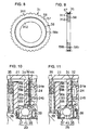
- the pilot friction clutch 32 is composed of one outer plate 44 and one inner plate 45. Further, in a second modified form of the embodiment shown in Figure 11, the pilot friction clutch 32 is composed of one inner plate 45 which is in position to directly contact to the armature 31. Like the aforementioned first embodiment, these modified forms take the configuration that the pilot friction clutch 32 is provided with at least two contact surfaces.
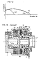
- Figure 12 is a graph which comparably shows the durability lives of the following samples S1 to S3 on the basis of ⁇ -V gradient (i.e., the dependence characteristic of friction coefficient ( ⁇ ) on speed (v)).
- the sample S1 takes the same construction as the foregoing embodiment wherein the magnetic flux (M) passes to reciprocate twice across the pilot friction dutch 32 composed of two outer plates 44 and one inner plate 45, as shown in Figure 3.
- the friction contact surfaces 44a of the outer plates 44 are given the aforementioned diamond-like carbon (DLC) surface treatment
- the friction contact surfaces 45a of the inner plate 45 are given the aforementioned gas soft-nitriding surface treatment using the special gas.
- DLC diamond-like carbon
- the sample S2 is different from the sample S1 only in that the friction contact surfaces 44a, 45a of the outer and Inner plates 44, 45 are both given the gas soft-nitriding surface treatment using the special gas.
- the sample S3 takes the same construction as the prior art device shown in Figure 13 wherein the magnetic flux (M) passes to reciprocate once across the pilot friction clutch 32 composed of four outer plates 44 and three inner plates 45. In this sample S3, the friction contact surfaces 44a, 45a of the outer and inner plates 44, 45 are both given the gas soft-nitriding surface treatment using the special gas.
- sample S1 is compared with the sample S2 which are the same in the number of the plates 44, 45, they have a large durable surface pressure because they are of the type that the magnetic flux passes to reciprocate twice.
- sample S2 in which only the gas soft-nitriding surface treatment using the special gas is given on the pilot friction clutch 32 is shorter in life than the sample S1 given the DLC surface treatment. Accordingly, it is understood that the DLC surface treatment is effective to extend the durability life of the pilot friction clutch 32.
- sample S2 is compared with the sample S3 which are both given only the gas soft-nitriding surface treatment using the special gas, it is understood that the sample S2 in which the durability surface pressure is made large with the magnetic flux reciprocating twice becomes shorter in the durability life than the sample S3 in which the magnetic flux passes to reciprocate once, because the former is smaller in the number of the plates 44, 45 than the latter.
- the sample S1 which is smaller in the number of the plates 44, 45 than the sample S3 ought to be larger in the durable surface pressure and ought to get shorter in the durability life because of the magnetic flux reciprocating twice. However, it is understood that the sample S1 can be recovered or extended in terms of the durability life owing to the DLC surface treatment and can have the same or slightly longer durability life than the sample S3 in spite of being smaller in the number of the plates 44, 45 than the sample S3.
- the sample S1 given the DLC surface treatment can maintain the durability life long by making the magnetic flux reciprocate twice across the pilot friction clutch 32 for a lager durable surface pressure, instead of decreasing the number of the plates 44, 45.
- the friction contact surfaces 44a of the outer plates 44 are given the diamond-like carbon (DLC) surface treatment
- the friction contract surfaces 45a of the inner plate 45 are given the gas soft-nitriding surface treatment using the special gas.
- the drive power transmittable by the pilot friction clutch 32 can be strengthened by reciprocatingly passing the magnetic flux plural times across the same even in the case that the number of the plates 44, 45 composing the pilot friction clutch 32 is reduced, the aforementioned diamond-like carbon (DLC) surface treatment is not necessarily needed. Therefore, it may be practiced to give both of the friction control surfaces 44a, 45a the gas soft-nitriding surface treatment using the special gas in substitution for the diamond-like carbon (DLC) surface treatment.
- the electromagnetic type clutch mechanism 30 generates a magnetic pass (M) including a clutch magnetic path whose magnetic flux passes to reciprocate plural times (twice in the illustrated embodiment) across the pilot friction clutch 32, as indicated at 59, 60 in Figure 3. Therefore, the friction contact force between the outer and inner plates 44, 45 can be strengthened, so that the clutch mechanism 30 can be constructed with a smaller number of the outer and inner plates 44, 45. This advantageously results in making the electromagnetic type clutch mechanism 30 and hence, the drive power transmission device 1 small in size and reducing the manufacturing cost.
- M magnetic pass
- the clutch magnetic path is generated to reciprocate at positions spaced radially from the rotational center axis 14a of the rotary members 12, 15.
- the clutch magnetic path may be generated to reciprocate three or more times instead of reciprocating twice in the illustrated embodiment.
- the first clutch magnetic path part 59 and the second clutch magnetic path part 60 of the clutch magnetic path are generated as segments of the magnetic path (M) connected in series, they may otherwise be generated as those independent of, or parallel to, each other.
- the electromagnetic type clutch mechanism 30 may be constructed to have at least two friction contact surfaces, as exemplified in Figures 10 and 11.
- a part or all of the friction contact surfaces of the outer and inner plates 44, 45 are given a surface treatment to have a hard amorphous carbon film formed thereon.
- this surface treatment can be practiced as the diamond-like carbon (DLC) surface treatment.
- DLC diamond-like carbon
- the diamond-like carbon (DLC) surface treatment may be given on the friction contact surfaces of either the outer plate 44 or the inner plate 45 or may be given on the friction contact surfaces of both of the plates 44, 45.
- DLC diamond-like carbon
- the present invention is not limited to the illustrated embodiment and rather, is applicable to various types of mechanisms such as stating clutch and the like for transmitting a torque between two rotational shafts.
- a drive power transmission device having a drive mechanism for transmitting a drive power between first and second rotary members rotatable relative to each other, by the operation of an electromagnetic type clutch mechanism which brings a friction dutch into connection.
- a magnetic path generated around an electromagnet of the electromagnetic type clutch mechanism includes a clutch magnetic path in which a magnetic flux passes to reciprocate plural times across the friction clutch, and diamond-like carbon surface treatment is given on a part or all of the friction contact surfaces of the friction clutch to form a hard amorphous carbon film thereon.
- the transmission device can be constructed using a smaller number of the outer and inner plates for the electromagnetic type clutch mechanism, so that it can take a small construction with a longer durability life.
Landscapes
- Engineering & Computer Science (AREA)
- General Engineering & Computer Science (AREA)
- Physics & Mathematics (AREA)
- Electromagnetism (AREA)
- Mechanical Engineering (AREA)
- Mechanical Operated Clutches (AREA)
Abstract
Description
Claims (11)
- A drive power transmission device provided with a drive mechanism for transmitting a drive power between first and second rotary members rotatable relative to each other, by the operation of an electromagnetic type clutch mechanism which brings a friction clutch into connection; wherein said friction clutch has plural friction contact surfaces, and wherein a magnetic path generated around an electromagnet of said electromagnetic type clutch mechanism includes a clutch magnetic path whose magnetic flux passes to reciprocate plural times across said friction clutch.
- A drive power transmission device as set forth in Claim 1, wherein said friction clutch has at least two friction contact surfaces.
- A drive power transmission device provided with a drive mechanism for transmitting a drive power between first and second rotary members rotatable relative to each other, by the operation of an electromagnetic type clutch mechanism which brings a friction clutch into connection; wherein a magnetic path generated around an electromagnet of said electromagnetic type clutch mechanism includes a clutch magnetic path whose magnetic flux passes to reciprocate plural times across said friction clutch, and wherein diamond-like carbon surface treatment is given on a part or all of the friction contact surfaces of said friction clutch.
- A drive power transmission device as set forth in Claim 3, wherein said friction clutch of said electromagnetic type clutch mechanism comprises plates which are brought into friction contact upon receiving the pressuring force which an armature exerts when attracted toward said electromagnet, and wherein said diamond-like carbon surface treatment is given on a part or all of the friction contact surfaces of said plates.
- A drive power transmission device as set forth in Claim 4, wherein said clutch magnetic path is generated through magnetic path areas of said plates and through magnetic path areas of said armature, said magnetic path areas of said plates being partitioned with partitioning spaces formed in said plates while said magnetic path areas of said armature is partitioned with partitioning spaces formed in said armature.
- A drive power transmission device comprising first and second cylindrical rotary members coaxially arranged to be rotatable relative to each other; a main clutch mechanism composed of plural main outer plates rotatable bodily with said first cylindrical rotary member and plural main inner plates rotatable bodily with said second cylindrical rotary member, said main outer plates being arranged in alternate fashion with said main inner plates each for friction contact with said main inner plates adjacent thereto; an electromagnetic type pilot clutch mechanism composed of a pilot outer plate rotatable bodily with said first cylindrical rotary member and a pilot inner plate engageable with said pilot outer plate for rotatable therewith, said electromagnetic type pilot clutch mechanism including an electromagnet unit for bringing said pilot outer and inner plates into friction contact with each other; and a cam mechanism operable upon receiving the rotational torque of said pilot inner plate for bringing said main outer and inner plates into friction contact, wherein said electromagnet unit and said pilot outer and inner plates include means for generating a clutch magnetic path whose magnetic flux passes to reciprocate plural times across said pilot outer and inner plates of said electromagnetic type pilot clutch mechanism.
- A drive power transmission device as set forth in Claim 6, wherein a part or all of friction contact surfaces of said pilot outer and inner plates are given diamond-like carbon surface treatment or soft-nitriding surface treatment.
- A drive power transmission device as set forth in Claim 7, wherein said means for passing said magnetic flux to reciprocate plural times across said pilot outer and inner plates comprises:a magnetic flux isolation member made of a non-magnetic material and formed with outer and inner cylindrical portions arranged coaxially with each other; andarc slits formed in said pilot outer and inner plates on at least triple circles whose outermost and innermost circles respectively correspond in diameter to said outer and inner cylindrical portions of said magnetic flux isolation member,said magnetic flux isolation member being arranged in axial alignment with said pilot outer and inner plates with said outer and inner cylindrical portions respectively facing said arc slits on said outermost circle and said arc slits on said innermost circle of said pilot outer and inner plates.
- A drive power transmission device as set forth in Claim 8, wherein said electromagnet unit includes an electromagnet for attracting said pilot outer and inner plates thereto and an armature arranged at a side opposite to said electromagnet for pressuring said pilot outer and inner plates on said electromagnet when attracted by the same, and wherein said means for passing said magnetic flux to reciprocate plural times across said pilot outer and inner plates further comprises:arc slits formed in said armature on a circle which corresponds in diameter to an intermediate circle between said outermost circle and said innermost circle and facing said arc slits formed in said pilot outer and inner plates on said intermediate circle.
- A drive power transmission device comprising first and second cylindrical rotary members coaxially arranged to be rotatable relative to each other; a main clutch mechanism composed of plural main outer plates rotatable bodily with said first cylindrical rotary member and plural main inner plates rotatable bodily with said second cylindrical rotary member, said main outer plates being arranged in alternate fashion with said main inner plates each for friction contact with said main inner plates adjacent thereto; an electromagnetic type pilot clutch mechanism composed of a pilot inner plate, an electromagnet for attracting said pilot inner plate thereto, and an armature rotatable bodily with said first cylindrical rotary member and movable axially relative thereto for pressuring said pilot inner plate on said electromagnet when attracted by the same; and a cam mechanism operable upon receiving the rotational torque of said pilot inner plate for bringing said main outer and inner plates into friction contact, wherein said electromagnetic type pilot clutch mechanism further includes means for generating a clutch magnetic path whose magnetic flux passes to reciprocate plural times across said pilot inner plate of said electromagnetic type pilot clutch mechanism.
- A drive power transmission device as set forth in Claim 10, wherein said means for generating said clutch magnetic path comprises:a magnetic flux isolation member made of a non-magnetic material and formed with outer and inner cylindrical portions arranged coaxially with each other;arc slits formed in said pilot inner plate on at least triple circles whose outermost and innermost circles respectively correspond in diameter to said outer and inner cylindrical portions of said magnetic flux isolation member; andarc slits formed in said armature on a circle which corresponds in diameter to an intermediate circle between said outermost circle and said innermost circle and facing said arc slits formed in said pilot inner plate on said intermediate circle.
Applications Claiming Priority (2)
| Application Number | Priority Date | Filing Date | Title |
|---|---|---|---|
| JP2002250036A JP2004084899A (en) | 2002-08-29 | 2002-08-29 | Driving force transmission device |
| JP2002250036 | 2002-08-29 |
Publications (3)
| Publication Number | Publication Date |
|---|---|
| EP1394436A2 true EP1394436A2 (en) | 2004-03-03 |
| EP1394436A3 EP1394436A3 (en) | 2004-03-10 |
| EP1394436B1 EP1394436B1 (en) | 2005-10-12 |
Family
ID=31492592
Family Applications (1)
| Application Number | Title | Priority Date | Filing Date |
|---|---|---|---|
| EP03019483A Expired - Lifetime EP1394436B1 (en) | 2002-08-29 | 2003-08-28 | Electromagnetic clutch |
Country Status (4)
| Country | Link |
|---|---|
| US (1) | US7004297B2 (en) |
| EP (1) | EP1394436B1 (en) |
| JP (1) | JP2004084899A (en) |
| DE (1) | DE60301835T2 (en) |
Cited By (1)
| Publication number | Priority date | Publication date | Assignee | Title |
|---|---|---|---|---|
| EP2672136A1 (en) * | 2012-06-07 | 2013-12-11 | Jtekt Corporation | Driving force transmission apparatus |
Families Citing this family (8)
| Publication number | Priority date | Publication date | Assignee | Title |
|---|---|---|---|---|
| JP2004308903A (en) * | 2003-04-07 | 2004-11-04 | Luk Lamellen & Kupplungsbau Beteiligungs Kg | Electromagnetic friction clutch |
| JP4622229B2 (en) * | 2003-10-16 | 2011-02-02 | 株式会社ジェイテクト | Driving force transmission device |
| DE102005041080A1 (en) * | 2004-08-31 | 2006-03-16 | Tochigi Fuji Sangyo K.K. | friction engagement |
| WO2007043637A1 (en) * | 2005-10-07 | 2007-04-19 | Jtekt Corporation | Spline shaft |
| JP2008057703A (en) * | 2006-08-31 | 2008-03-13 | Gkn ドライブライン トルクテクノロジー株式会社 | Electromagnetic clutch device |
| WO2009023414A1 (en) * | 2007-08-13 | 2009-02-19 | Borgwarner Inc. | Torque feedback sensor |
| WO2015056330A1 (en) * | 2013-10-17 | 2015-04-23 | Gkn ドライブライン ジャパン株式会社 | Clutch device and differential device with reduced friction loss |
| US10982750B2 (en) * | 2018-10-01 | 2021-04-20 | Dana Automotive Systems Group, Llc | Retention system |
Family Cites Families (18)
| Publication number | Priority date | Publication date | Assignee | Title |
|---|---|---|---|---|
| US230412A (en) * | 1880-07-27 | John gardner | ||
| US236042A (en) * | 1880-12-28 | Draft-equalizer for side reaping-machines | ||
| US242169A (en) * | 1881-05-31 | Method of ventilating sewers and drains | ||
| US4958712A (en) | 1987-06-29 | 1990-09-25 | Taiho Kogyo Co. Ltd. | Wet clutch device |
| US4988421A (en) * | 1989-01-12 | 1991-01-29 | Ford Motor Company | Method of toughening diamond coated tools |
| JPH06100240B2 (en) * | 1990-04-10 | 1994-12-12 | 輝幸 綱渕 | Friction material mating surface |
| US5242040A (en) * | 1992-03-10 | 1993-09-07 | Sanden Corporation | Structure of rotor of electromagnetic clutch |
| US5651430A (en) | 1992-03-31 | 1997-07-29 | Rancourt; Claude | Disc brake assembly |
| JPH07224861A (en) * | 1993-08-31 | 1995-08-22 | Nippondenso Co Ltd | Electromagnetic clutch |
| US5404980A (en) * | 1994-04-11 | 1995-04-11 | Ford Motor Company | Electromagnetic clutch with failure protection apparatus |
| US5735375A (en) * | 1996-05-31 | 1998-04-07 | Dana Corporation | Nitrocarburized component for an electromagnetic friction clutch assembly |
| DE69736790T2 (en) * | 1996-06-27 | 2007-08-16 | Nissin Electric Co., Ltd. | Carbon film coated article and method of making the same |
| JP3893682B2 (en) * | 1997-08-26 | 2007-03-14 | 株式会社デンソー | Electromagnetic clutch |
| DE69937081T2 (en) * | 1998-04-01 | 2008-06-12 | Jtekt Corp. | clutch disc |
| US6098770A (en) * | 1999-03-19 | 2000-08-08 | Borgwarner Inc. | Clutch assembly having reaction force circuit |
| KR100436829B1 (en) * | 1999-06-18 | 2004-06-23 | 닛신덴키 가부시키 가이샤 | Carbon film and method for formation thereof and article covered with carbon film and method for preparation thereof |
| DE10039242A1 (en) * | 1999-08-24 | 2001-03-08 | Luk Lamellen & Kupplungsbau | Disengagement system for motor vehicle clutches comprises a disengagement unit which has a plastic housing and is centrally installed into a bore of the transmission housing around the transmission input shaft |
| JP4638571B2 (en) | 2000-04-17 | 2011-02-23 | トヨタ自動車株式会社 | Electromagnetic two-way clutch |
-
2002
- 2002-08-29 JP JP2002250036A patent/JP2004084899A/en active Pending
-
2003
- 2003-08-28 DE DE60301835T patent/DE60301835T2/en not_active Expired - Lifetime
- 2003-08-28 US US10/649,730 patent/US7004297B2/en not_active Expired - Lifetime
- 2003-08-28 EP EP03019483A patent/EP1394436B1/en not_active Expired - Lifetime
Cited By (2)
| Publication number | Priority date | Publication date | Assignee | Title |
|---|---|---|---|---|
| EP2672136A1 (en) * | 2012-06-07 | 2013-12-11 | Jtekt Corporation | Driving force transmission apparatus |
| US8905208B2 (en) | 2012-06-07 | 2014-12-09 | Jtekt Corporation | Driving force transmission apparatus |
Also Published As
| Publication number | Publication date |
|---|---|
| EP1394436A3 (en) | 2004-03-10 |
| DE60301835T2 (en) | 2006-07-20 |
| US7004297B2 (en) | 2006-02-28 |
| JP2004084899A (en) | 2004-03-18 |
| DE60301835D1 (en) | 2005-11-17 |
| EP1394436B1 (en) | 2005-10-12 |
| US20040134736A1 (en) | 2004-07-15 |
Similar Documents
| Publication | Publication Date | Title |
|---|---|---|
| US5269730A (en) | Differential gear device for vehicle | |
| EP1394436B1 (en) | Electromagnetic clutch | |
| EP4023481B1 (en) | Drive system for four-wheel drive vehicle | |
| JP2008014419A (en) | Differential device | |
| JP2004092741A (en) | Electromagnetic brake | |
| EP1394437A1 (en) | Electromagnetic clutch | |
| EP1473488A2 (en) | Combination of drive power transmission device and differential gear and manufacturing method therefor | |
| EP1227259B1 (en) | Drive force transmission apparatus | |
| JP4076361B2 (en) | Power switching device | |
| JP4202587B2 (en) | Driving force transmission device and adjustment method thereof | |
| JP2003011693A (en) | Differential device | |
| US6786314B2 (en) | Electromagnetic clutch structure in driving force distribution system | |
| US6637572B2 (en) | Electromagnetic clutch structure in driving force distribution system | |
| JP3847359B2 (en) | Differential limiter | |
| JPH0464747A (en) | Differential limiting device | |
| JP2003039968A (en) | Power transmission device | |
| US6708806B2 (en) | Power transmission apparatus | |
| JP2006300337A (en) | Driving force transmission device | |
| JPH10213163A (en) | Driving force transmission device | |
| JP2003191769A (en) | Two-wheel four-wheel drive switching device for vehicles | |
| JPH06147236A (en) | Clutch device | |
| JP2004116764A (en) | Magnetic path forming member, clutch mechanism, driving force transmission device, and manufacturing method of magnetic path forming member | |
| JPH1130248A (en) | Driving force transmission device | |
| JP2000081054A (en) | Electromagnetic clutch device | |
| JPH11153158A (en) | Driving force transmission device |
Legal Events
| Date | Code | Title | Description |
|---|---|---|---|
| PUAI | Public reference made under article 153(3) epc to a published international application that has entered the european phase |
Free format text: ORIGINAL CODE: 0009012 |
|
| PUAL | Search report despatched |
Free format text: ORIGINAL CODE: 0009013 |
|
| AK | Designated contracting states |
Kind code of ref document: A2 Designated state(s): AT BE BG CH CY CZ DE DK EE ES FI FR GB GR HU IE IT LI LU MC NL PT RO SE SI SK TR |
|
| AX | Request for extension of the european patent |
Extension state: AL LT LV MK |
|
| AK | Designated contracting states |
Kind code of ref document: A3 Designated state(s): AT BE BG CH CY CZ DE DK EE ES FI FR GB GR HU IE IT LI LU MC NL PT RO SE SI SK TR |
|
| AX | Request for extension of the european patent |
Extension state: AL LT LV MK |
|
| 17P | Request for examination filed |
Effective date: 20040819 |
|
| AKX | Designation fees paid |
Designated state(s): DE FR GB |
|
| 17Q | First examination report despatched |
Effective date: 20040914 |
|
| GRAP | Despatch of communication of intention to grant a patent |
Free format text: ORIGINAL CODE: EPIDOSNIGR1 |
|
| GRAS | Grant fee paid |
Free format text: ORIGINAL CODE: EPIDOSNIGR3 |
|
| GRAA | (expected) grant |
Free format text: ORIGINAL CODE: 0009210 |
|
| AK | Designated contracting states |
Kind code of ref document: B1 Designated state(s): DE FR GB |
|
| REG | Reference to a national code |
Ref country code: GB Ref legal event code: FG4D |
|
| REF | Corresponds to: |
Ref document number: 60301835 Country of ref document: DE Date of ref document: 20051117 Kind code of ref document: P |
|
| ET | Fr: translation filed | ||
| PLBE | No opposition filed within time limit |
Free format text: ORIGINAL CODE: 0009261 |
|
| STAA | Information on the status of an ep patent application or granted ep patent |
Free format text: STATUS: NO OPPOSITION FILED WITHIN TIME LIMIT |
|
| 26N | No opposition filed |
Effective date: 20060713 |
|
| PGFP | Annual fee paid to national office [announced via postgrant information from national office to epo] |
Ref country code: GB Payment date: 20080903 Year of fee payment: 6 |
|
| GBPC | Gb: european patent ceased through non-payment of renewal fee |
Effective date: 20090828 |
|
| PG25 | Lapsed in a contracting state [announced via postgrant information from national office to epo] |
Ref country code: GB Free format text: LAPSE BECAUSE OF NON-PAYMENT OF DUE FEES Effective date: 20090828 |
|
| REG | Reference to a national code |
Ref country code: FR Ref legal event code: PLFP Year of fee payment: 14 |
|
| REG | Reference to a national code |
Ref country code: FR Ref legal event code: PLFP Year of fee payment: 15 |
|
| REG | Reference to a national code |
Ref country code: FR Ref legal event code: PLFP Year of fee payment: 16 |
|
| PGFP | Annual fee paid to national office [announced via postgrant information from national office to epo] |
Ref country code: DE Payment date: 20220712 Year of fee payment: 20 |
|
| PGFP | Annual fee paid to national office [announced via postgrant information from national office to epo] |
Ref country code: FR Payment date: 20220709 Year of fee payment: 20 |
|
| REG | Reference to a national code |
Ref country code: DE Ref legal event code: R071 Ref document number: 60301835 Country of ref document: DE |