EP1393960A2 - Engine torque control apparatus - Google Patents
Engine torque control apparatus Download PDFInfo
- Publication number
- EP1393960A2 EP1393960A2 EP03019357A EP03019357A EP1393960A2 EP 1393960 A2 EP1393960 A2 EP 1393960A2 EP 03019357 A EP03019357 A EP 03019357A EP 03019357 A EP03019357 A EP 03019357A EP 1393960 A2 EP1393960 A2 EP 1393960A2
- Authority
- EP
- European Patent Office
- Prior art keywords
- engine
- engine torque
- temperature
- oil
- controller
- Prior art date
- Legal status (The legal status is an assumption and is not a legal conclusion. Google has not performed a legal analysis and makes no representation as to the accuracy of the status listed.)
- Granted
Links
Images


Classifications
-
- F—MECHANICAL ENGINEERING; LIGHTING; HEATING; WEAPONS; BLASTING
- F02—COMBUSTION ENGINES; HOT-GAS OR COMBUSTION-PRODUCT ENGINE PLANTS
- F02D—CONTROLLING COMBUSTION ENGINES
- F02D45/00—Electrical control not provided for in groups F02D41/00 - F02D43/00
-
- B—PERFORMING OPERATIONS; TRANSPORTING
- B60—VEHICLES IN GENERAL
- B60W—CONJOINT CONTROL OF VEHICLE SUB-UNITS OF DIFFERENT TYPE OR DIFFERENT FUNCTION; CONTROL SYSTEMS SPECIALLY ADAPTED FOR HYBRID VEHICLES; ROAD VEHICLE DRIVE CONTROL SYSTEMS FOR PURPOSES NOT RELATED TO THE CONTROL OF A PARTICULAR SUB-UNIT
- B60W10/00—Conjoint control of vehicle sub-units of different type or different function
- B60W10/04—Conjoint control of vehicle sub-units of different type or different function including control of propulsion units
- B60W10/06—Conjoint control of vehicle sub-units of different type or different function including control of propulsion units including control of combustion engines
-
- B—PERFORMING OPERATIONS; TRANSPORTING
- B60—VEHICLES IN GENERAL
- B60W—CONJOINT CONTROL OF VEHICLE SUB-UNITS OF DIFFERENT TYPE OR DIFFERENT FUNCTION; CONTROL SYSTEMS SPECIALLY ADAPTED FOR HYBRID VEHICLES; ROAD VEHICLE DRIVE CONTROL SYSTEMS FOR PURPOSES NOT RELATED TO THE CONTROL OF A PARTICULAR SUB-UNIT
- B60W10/00—Conjoint control of vehicle sub-units of different type or different function
- B60W10/04—Conjoint control of vehicle sub-units of different type or different function including control of propulsion units
-
- B—PERFORMING OPERATIONS; TRANSPORTING
- B60—VEHICLES IN GENERAL
- B60W—CONJOINT CONTROL OF VEHICLE SUB-UNITS OF DIFFERENT TYPE OR DIFFERENT FUNCTION; CONTROL SYSTEMS SPECIALLY ADAPTED FOR HYBRID VEHICLES; ROAD VEHICLE DRIVE CONTROL SYSTEMS FOR PURPOSES NOT RELATED TO THE CONTROL OF A PARTICULAR SUB-UNIT
- B60W10/00—Conjoint control of vehicle sub-units of different type or different function
- B60W10/10—Conjoint control of vehicle sub-units of different type or different function including control of change-speed gearings
- B60W10/101—Infinitely variable gearings
-
- B—PERFORMING OPERATIONS; TRANSPORTING
- B60—VEHICLES IN GENERAL
- B60W—CONJOINT CONTROL OF VEHICLE SUB-UNITS OF DIFFERENT TYPE OR DIFFERENT FUNCTION; CONTROL SYSTEMS SPECIALLY ADAPTED FOR HYBRID VEHICLES; ROAD VEHICLE DRIVE CONTROL SYSTEMS FOR PURPOSES NOT RELATED TO THE CONTROL OF A PARTICULAR SUB-UNIT
- B60W30/00—Purposes of road vehicle drive control systems not related to the control of a particular sub-unit, e.g. of systems using conjoint control of vehicle sub-units
- B60W30/18—Propelling the vehicle
- B60W30/1819—Propulsion control with control means using analogue circuits, relays or mechanical links
-
- B—PERFORMING OPERATIONS; TRANSPORTING
- B60—VEHICLES IN GENERAL
- B60W—CONJOINT CONTROL OF VEHICLE SUB-UNITS OF DIFFERENT TYPE OR DIFFERENT FUNCTION; CONTROL SYSTEMS SPECIALLY ADAPTED FOR HYBRID VEHICLES; ROAD VEHICLE DRIVE CONTROL SYSTEMS FOR PURPOSES NOT RELATED TO THE CONTROL OF A PARTICULAR SUB-UNIT
- B60W30/00—Purposes of road vehicle drive control systems not related to the control of a particular sub-unit, e.g. of systems using conjoint control of vehicle sub-units
- B60W30/18—Propelling the vehicle
- B60W30/184—Preventing damage resulting from overload or excessive wear of the driveline
-
- B—PERFORMING OPERATIONS; TRANSPORTING
- B60—VEHICLES IN GENERAL
- B60W—CONJOINT CONTROL OF VEHICLE SUB-UNITS OF DIFFERENT TYPE OR DIFFERENT FUNCTION; CONTROL SYSTEMS SPECIALLY ADAPTED FOR HYBRID VEHICLES; ROAD VEHICLE DRIVE CONTROL SYSTEMS FOR PURPOSES NOT RELATED TO THE CONTROL OF A PARTICULAR SUB-UNIT
- B60W30/00—Purposes of road vehicle drive control systems not related to the control of a particular sub-unit, e.g. of systems using conjoint control of vehicle sub-units
- B60W30/18—Propelling the vehicle
- B60W30/192—Mitigating problems related to power-up or power-down of the driveline, e.g. start-up of a cold engine
- B60W30/194—Mitigating problems related to power-up or power-down of the driveline, e.g. start-up of a cold engine related to low temperature conditions, e.g. high viscosity of hydraulic fluid
-
- F—MECHANICAL ENGINEERING; LIGHTING; HEATING; WEAPONS; BLASTING
- F16—ENGINEERING ELEMENTS AND UNITS; GENERAL MEASURES FOR PRODUCING AND MAINTAINING EFFECTIVE FUNCTIONING OF MACHINES OR INSTALLATIONS; THERMAL INSULATION IN GENERAL
- F16H—GEARING
- F16H61/00—Control functions within control units of change-speed- or reversing-gearings for conveying rotary motion ; Control of exclusively fluid gearing, friction gearing, gearings with endless flexible members or other particular types of gearing
- F16H61/66—Control functions within control units of change-speed- or reversing-gearings for conveying rotary motion ; Control of exclusively fluid gearing, friction gearing, gearings with endless flexible members or other particular types of gearing specially adapted for continuously variable gearings
-
- B—PERFORMING OPERATIONS; TRANSPORTING
- B60—VEHICLES IN GENERAL
- B60W—CONJOINT CONTROL OF VEHICLE SUB-UNITS OF DIFFERENT TYPE OR DIFFERENT FUNCTION; CONTROL SYSTEMS SPECIALLY ADAPTED FOR HYBRID VEHICLES; ROAD VEHICLE DRIVE CONTROL SYSTEMS FOR PURPOSES NOT RELATED TO THE CONTROL OF A PARTICULAR SUB-UNIT
- B60W2510/00—Input parameters relating to a particular sub-units
- B60W2510/10—Change speed gearings
- B60W2510/107—Temperature
-
- B—PERFORMING OPERATIONS; TRANSPORTING
- B60—VEHICLES IN GENERAL
- B60W—CONJOINT CONTROL OF VEHICLE SUB-UNITS OF DIFFERENT TYPE OR DIFFERENT FUNCTION; CONTROL SYSTEMS SPECIALLY ADAPTED FOR HYBRID VEHICLES; ROAD VEHICLE DRIVE CONTROL SYSTEMS FOR PURPOSES NOT RELATED TO THE CONTROL OF A PARTICULAR SUB-UNIT
- B60W2710/00—Output or target parameters relating to a particular sub-units
- B60W2710/06—Combustion engines, Gas turbines
- B60W2710/0666—Engine torque
-
- F—MECHANICAL ENGINEERING; LIGHTING; HEATING; WEAPONS; BLASTING
- F16—ENGINEERING ELEMENTS AND UNITS; GENERAL MEASURES FOR PRODUCING AND MAINTAINING EFFECTIVE FUNCTIONING OF MACHINES OR INSTALLATIONS; THERMAL INSULATION IN GENERAL
- F16H—GEARING
- F16H59/00—Control inputs to control units of change-speed- or reversing-gearings for conveying rotary motion
- F16H59/68—Inputs being a function of gearing status
- F16H59/72—Inputs being a function of gearing status dependent on oil characteristics, e.g. temperature, viscosity
Definitions
- This invention relates to a control apparatus for controlling the output torque of an engine to a transmission system for transmitting the driving force of the engine to a driving wheel.
- a belt CVT Continuous Variable Transmission
- a belt CVT comprises a primary pulley for inputting the driving force of the engine, a secondary pulley for outputting the driving force to the driving wheel, and a V-belt wound around the primary pulley and secondary pulley for transmitting the driving force inputted from the primary pulley to the secondary pulley.
- the pulley width of the primary pulley and the secondary pulley can be varied by the oil pressure supplied to the primary pulley and secondary pulley.
- oil pressure supplied to the primary pulley and secondary pulley adjusts the pulley width and thus to vary the ratio (pulley ratio) of the contact radius (effective radius) in relation to the primary pulley and secondary pulley of the V-belt.
- the ratio of rotation speed (gear ratio) between input and output is adjusted.
- Belt slippage does not occur in the belt CVT in order to prevent reduction in belt durability.
- Belt slippage can be prevented by increasing the oil pressure supplied to the primary pulley and secondary pulley to thereby increase the force at which the primary pulley and secondary pulley hold the V-belt.
- An object of this invention is to provide an engine output control apparatus whereby it is possible for the vehicle to run smoothly and for belt slippage in the belt CVT to be prevented without the occurrence of large shocks even at low temperatures.
- this invention provides an engine torque control apparatus for controlling an output torque of an engine connected to a transmission in a vehicle.
- the engine torque control apparatus comprises a temperature sensor for detecting a temperature of oil supplied to the transmission and a controller for limiting the output torque of the engine to an engine torque limit or less, the controller being linked to the temperature sensor.
- the controller functions to compare the oil temperature with a specific temperature; set the engine torque limit to a first value when the oil temperature is equal to or less than the specific temperature; and increase the engine torque limit at a predetermined increase rate when the oil temperature is greater than the specific temperature.
- this invention provides a control method for controlling an output torque of an engine connected to a transmission in a vehicle.
- the control method comprises the steps of detecting a temperature of oil supplied to the transmission; comparing the oil temperature with a specific temperature; setting an engine torque limit to a first value when the oil temperature is equal to or less than the specific temperature; increasing the engine torque limit at a predetermined increase rate when the oil temperature is greater than the specific temperature; and limiting the output torque of the engine to the engine torque limit or less.
- Fig. 1 is a schematic structural diagram showing a control apparatus for controlling the engine torque to a transmission system for a vehicle according to the first embodiment.
- Fig. 2 is a map showing the relationship between the engine rotation speed and target engine torque at each quantity of accelerator pedal travel (throttle valve opening).
- Fig. 3 is a flow chart showing the control executed by the engine torque control apparatus according to the first embodiment.
- Fig. 4A is a graph showing the temporal change in engine torque limit and the temporal change in engine torque according to the first embodiment
- Fig. 4B is a graph showing the temporal change in oil temperature.
- Fig. 5A is a graph showing the temporal change in engine torque limit and the temporal change in engine torque according to conventional art
- Fig. 5B is a graph showing the temporal change in oil temperature.
- Fig. 6 is a flow chart showing the control executed by the engine torque control apparatus according to the second embodiment.
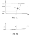
- Fig. 7A is a graph showing the temporal change in engine torque limit and the temporal change in engine torque according to the second embodiment
- Fig. 7B is a graph showing the temporal change in oil temperature.
- Fig. 1 shows a control apparatus for controlling the engine torque inputted to a transmission system for a vehicle.
- the transmission system 1 comprises a pump 10, a torque converter 20, a forward-reverse switching apparatus 30, and a transmission 40.
- the transmission system 1 converts the torque outputted from an engine 60 and transmits it to a driving wheel 70.
- the controller 50 for controlling the engine 60 comprises a microcomputer 80, a fuel injector 61 for injecting fuel into the engine 60, a throttle valve 63 for controlling the air intake of the engine 60, and an ignition apparatus 65 for igniting the fuel.
- the fuel injector 61, the throttle valve 63, and the ignition apparatus 65 are capable of operating according to command signals from the microcomputer 80.
- the microcomputer 80 has a central processing unit (CPU) for running programs, read-only memory (ROM) for storing programs and data, random access memory (RAM) for temporarily storing data acquired as computing results from the CPU, and an input/output interface (I/O interface).
- the controller 50 may comprise a plurality of microcomputers.
- the controller 50 controls the engine torque Te and the engine rotation speed Ne by adjusting the quantity of fuel injected by the fuel injector 61, the opening of the throttle valve, or the ignition timing of the ignition apparatus 65, or a plurality of thereof.
- the engine rotation speed Ne is detected by an engine revolution sensor 67.
- An accelerator pedal sensor 54 detects the travel (depression amount) of an accelerator pedal 57.
- the throttle valve opening TVO corresponds to the accelerator pedal travel. Therefore, an accelerator pedal sensor 54 indirectly detects the throttle valve opening TVO.
- a sensor that directly detects the throttle valve opening may also be provided.
- a shift lever 53 is used so that the user can change the operating range of the transmission system.
- the operating range of the transmission system includes at least a drive range (D range) for moving the vehicle forward, a reverse range (R range) for moving the vehicle backward, and a neutral range (N range) or a parking range (P range) for stopping the vehicle.
- the pump 10 is driven by the revolutions of the engine 60 and is designed to pump oil.
- the pressure of the pumped oil is adjusted, after which the oil is sent to the forward-reverse switching apparatus 30 and the transmission 40, and is utilized in forward-reverse switching and gear shifting.
- the oil pressure is adjusted by a pressure regulating valve (not shown).
- the torque converter 20 is provided between the engine 60 and the forward-reverse switching apparatus 30, and the drive force of the engine 60 is transmitted by the current of the oil inside the torque converter 20.
- the forward-reverse switching apparatus 30 has a planetary gear set 31 for changing the power transmission path between the engine and the transmission, a forward clutch board 32, and a reverse clutch board 33.
- the forward clutch board 32 is joined to a forward clutch piston, and is connected to the planetary gear set 31 by the force of the oil pressure (forward clutch pressure) supplied to a forward clutch piston chamber 32a in the D range.
- the reverse clutch board 33 is joined to a reverse clutch piston, and is connected to the planetary gear set 31 by the force of the oil pressure (reverse clutch pressure) supplied to a reverse clutch piston chamber 33a in the R range. In the N range and P range, oil is not supplied and the forward clutch board 32 and reverse clutch board 33 are released together.
- a direction control valve (not shown) for controlling the supply direction of the oil selects the engagement of the forward clutch board 32 or the reverse clutch board 33.
- the direction control valve switches the supply direction of the oil between the direction toward the forward clutch piston chamber 32a and the direction toward the reverse clutch piston chamber 33a.
- the forward clutch board 32 and the reverse clutch board 33 are released together by releasing the forward clutch pressure and the reverse clutch pressure into a drain.
- the direction control valve is in the middle position, and oil is not supplied to the forward clutch piston chamber 32a or the reverse clutch piston chamber 33a.
- the transmission 40 is a belt CVT but is not limited thereto.
- Such a transmission 40 comprises a primary pulley 41, a secondary pulley 42, and a V-belt 43.
- the primary pulley 41 is an input pulley in which the driving force of the engine 60 is inputted.
- the primary pulley 41 comprises a fixed conical plate 41a that rotates in unison with the input shaft 41c and a movable conical plate 41b capable of being displaced.
- a V-shaped pulley groove is formed between the fixed conical plate 41a and the movable conical plate 41b, and the V-shaped V-belt 43 is disposed in the pulley groove.
- the movable conical plate 41b is displaced in the input shaft direction by the oil pressure acting on the primary pulley 41 (hereinafter referred to as "primary pressure").
- the revolution speed N1 of the primary pulley 41 is detected by a revolution speed sensor 51 for the primary pulley.
- the secondary pulley 42 transmits the driving force transmitted by the V-belt 43 to the driving wheel 70 via an idler gear or a differential gear.
- the secondary pulley 42 comprises a fixed conical plate 42a that rotates in unison with an output shaft 42c, and a movable conical plate 42b capable of being displaced.
- a V-shaped pulley groove is formed between the fixed conical plate 42a and the movable conical plate 42b, and the V-belt 43 is disposed in the pulley groove.
- the movable conical plate 42b is displaced in the output shaft direction in response to the oil pressure acting on the secondary pulley (hereinafter referred to as "secondary pressure").
- the pressurized area of the secondary pulley and the pressurized area of the primary pulley are equal or nearly equal.
- the revolution speed of the secondary pulley 42 is detected by a revolution speed sensor 52 for the secondary pulley.
- the speed of the vehicle is calculated from the revolution speed N2 of the secondary pulley 42.
- the V-belt 43 is wound around the primary pulley 41 and secondary pulley 42, and transmits the driving force inputted by the primary pulley 41 to the secondary pulley 42.
- the controller 50 calculates the speed ratio (N1 / N2) of the transmission 40 based on signals from the revolution speed sensor 51 for the primary pulley and the revolution speed sensor 52 for the secondary pulley.
- the maximum transmittable torque of the transmission 40 is calculated based on the speed ratio and a secondary oil pressure signal P2 from an oil pressure sensor 45b, referring to a map (not shown) which associates the maximum transmittable torque with the speed ratio and the secondary oil pressure.
- the transmission 40 can transmit the torque less than the maximum transmittable torque without a slip of the V-belt 43.
- the controller 50 also controls the direction control valve (not shown) and controls the supply of oil to the forward clutch piston chamber 32a and the reverse clutch piston chamber 33a; in other words, adjusts the forward clutch pressure and the reverse clutch pressure, thereby controlling the connected state of the clutch. Furthermore, when the forward clutch board 32 and the reverse clutch board 33 change from a released state to a connected state in relation to the planetary gear set 31, the controller 50 rapidly fills oil into the forward clutch piston chamber 32a or the reverse clutch piston chamber 33a via the direction control valve, quickly increasing the forward or reverse clutch pressure up to the connection pressure which is required to connect the clutch.
- the controller 50 reads the revolution speed N1 of the primary pulley and the revolution speed N2 of the secondary pulley and computes the speed ratio (N1 / N2), which is the ratio of the rotation speed N1 of the primary pulley to the rotation speed N2 of the secondary pulley.
- the controller 50 reads the range signal Rs from a shift lever position sensor 90 for detecting the position of the shift lever 53, the signal of a vehicle speed (namely, the rotation speed of the secondary pulley), the signal from the accelerator pedal sensor 54, the signal from an oil temperature sensor 55, and the oil pressure signals from the oil pressure sensors 45a, 45b, and determines the desired speed ratio based on these signals and the actual speed ratio.
- the controller 50 calculates the desired pressure of the primary pressure and secondary pressure for achieving the desired speed ratio, and controls a pressure regulating valve (not shown) to adjust the oil pressure supplied to the primary pulley 41 and the secondary pulley 42 to achieve the desired pressure.
- Fig. 2 is a map showing the relationship between the engine rotation speed and engine torque at each quantity of throttle valve opening TVO.
- the controller 50 stores the map in Fig. 2 in the ROM of the microcomputer 80. Referring to the map, the microcomputer 80 can calculate the target engine torque tTe based on the accelerator pedal travel TVO and the engine rotation speed Ne .
- the controller 50 limits the engine torque (which corresponds to the input torque of the transmission system 1) at a first limiting value, and when the oil temperature is greater than a specific temperature, the engine torque limit Tl is gradually raised. Gradually raising the engine torque limit Tl prevents belt slippage at low temperatures and also prevents shocks resulting from raising the engine torque limit Tl .
- the control routine for controlling the engine torque performed by the controller 50 will be described with reference to the flow chart shown in Fig. 3.
- the control routine is performed repetitively.
- step S11 it is determined whether the oil temperature To received from the oil temperature sensor 55 is equal to or less than a predetermined oil temperature of -20°C. If the determination is affirmative, the routine proceeds to step S12.
- the reason that the specific temperature is -20°C or less is because preferable oil pressure cannot be obtained at a temperature of -20°C or less as a result of high oil viscosity.
- the specific temperature depends on the type of oil.
- step S12 the maximum transmittable torque of the transmission 40 is calculated from the actual oil pressure and the speed ratio, and the engine torque limit Tl is set at the first limiting value which is equal to the maximum transmittable torque in this embodiment.
- the maximum transmittable torque is the maximum torque that the .transmission 40 can transmit at a temperature of - 20°C or less.
- step S13 the engine torque is kept below the engine torque limit Tl in a state of maintaining the engine torque limit Tl . For example, this is done by controlling the amount of fuel supplied to the engine.
- step S14 it is determined whether the oil temperature To is greater than -20°C. When the determination is negative, the routine returns to step S13 and the engine torque limit Tl continues to be maintained. When the oil temperature To is greater than -20°C, the routine proceeds to step S15.
- step S15 the engine torque limit Tl increases by an increment of ⁇ Tr (for example 2 Nm).
- step S16 the wait time tw is set at a predetermined short time of the order of milliseconds, and the routine is stopped during the wait time tw.
- the predetermined short time is 10 msec.
- step S17 it is determined whether the engine torque limit Tl is greater than or equal to the target engine torque tTe. If the determination is negative, the routine returns to step S15 and the engine torque limit Tl continues to gradually increase.
- the engine torque limit Tl increases at a predetermined increase rate (for example 200 Nm/sec) by repeating steps S15 and S16.
- the routine proceeds to step S18.
- the target engine torque tTe is the original engine torque to be outputted by the engine, which is calculated based on the engine rotation speed Ne and the accelerator pedal travel (i.e. the throttle valve opening TVO).
- step S18 the engine torque limit Tl is set at a second limiting value so that the original engine torque to be outputted by the engine is not limited.
- the second limiting value is greater than the maximum output torque of the engine 60, and is preferably near the maximum output torque of the engine 60.
- the engine 60 can output the target engine torque tTe calculated with reference to Fig. 2 from the engine rotation speed Ne and the accelerator pedal travel TVO .
- Fig. 4A shows the change over time in engine torque limit Tl at engine start-up and in real input torque from the engine to the transmission system.
- the thick solid line shows the engine torque limit Tl, and the dashed line shows the input torque from the engine.
- the part of the graph showing the increasing engine torque limit Tl is enlarged.
- Fig. 4B shows the change over time in oil temperature.
- the oil temperature is -20°C or less until time t1 (see Fig. 4B).
- the engine torque limit Tl is set at the first limiting value to control the input torque from the engine.
- the first limiting value is the maximum transmittable torque of the transmission 40 (Fig. 4A), which is 100 Nm in this embodiment.
- the engine torque limit Tl increases by a predetermined value ⁇ Tr every 10 ms after the oil temperature exceeds -20°C at time t1.
- the dashed line in Fig. 4A the input torque from the engine to the transmission system gradually rises.
- the engine torque limit Tl becomes the target engine torque tTe (for example, 300 Nm)
- the engine torque limit Tl is changed to the second limiting value (for example, 400 Nm) in order to ensure that the limit on the engine torque is substantially removed.
- the second limiting value is greater than the maximum output torque of the engine 60. Then the engine outputs the target torque calculated based on Fig. 2 from the engine rotation speed and the accelerator pedal travel TVO.
- Fig. 5 is a graph showing the setting of the conventional engine torque limit and the corresponding input torque from the engine to the transmission system.
- the lines are the same as in Fig. 4, where the thick solid line shows the engine torque limit, the dashed line shows the input torque from the engine, and the thin solid line shows the target engine torque.
- the engine torque limit is increased all at once to the maximum output torque of the engine when the oil temperature has exceeded (time t1) a specific temperature (for example, -20°C).
- a specific temperature for example, -20°C.
- the engine torque limit increases discontinuously from the first limiting value (for example, 100 Nm) to the second limiting value (for example, 400 Nm) and the increase rate of the engine torque limit is infinite. Therefore, the engine torque suddenly increases, resulting in a large shock.
- a second embodiment of the engine torque control apparatus will be described with reference to the flow chart shown in Fig. 6.
- the first embodiment and second embodiment differ in terms of the engine torque control performed by the controller 50, and other characteristics are common in the first embodiment and second embodiment.
- Fig. 6 is a control routine for controlling the engine torque performed by the controller 50. Identical symbols are used in the same steps as in Fig. 3, which depicts the first embodiment, and explanations thereof are omitted.
- steps S21 and S22 are introduced between steps S14 and S15 in Fig. 3 of the first embodiment.
- the accelerator pedal travel TVO is read in step S21.
- the increment ⁇ Tr of the engine torque limit Tl are set in response to the accelerator pedal travel TVO in the step S22.
- the increment ⁇ Tr increases according to the increase in the accelerator pedal travel TVO.
- the increase rate of the engine torque limit Tl increases according to the increase in the accelerator pedal travel TVO.
- the increase rate of the engine torque limit Tl decreases as well.
- Figs. 7A and 7B show the engine torque limit Tl when the accelerator pedal travel is large.
- the engine torque limit Tl when the accelerator pedal travel is small is shown by the dashed line.
- Fig. 7B shows the change over time in oil temperature.
- the dashed line showing the input torque from the engine to the transmission system is not shown in Fig. 7A, but the input torque changes along the line of the engine torque limit similar to Fig. 4A.
- the increase rate of the engine torque limit Tl increases as the accelerator pedal travel TVO increases.
- the accelerator pedal travel TVO is large, the engine torque limit increases quickly.
- the accelerator pedal travel TVO is small, the engine torque limit Tl increases slowly. Since the engine torque is required to rapidly increase when the accelerator pedal travel is large, the increase rate of the engine torque limit Tl is increased.
Landscapes
- Engineering & Computer Science (AREA)
- Mechanical Engineering (AREA)
- Chemical & Material Sciences (AREA)
- Combustion & Propulsion (AREA)
- Transportation (AREA)
- Automation & Control Theory (AREA)
- General Engineering & Computer Science (AREA)
- Control Of Vehicle Engines Or Engines For Specific Uses (AREA)
- Control Of Transmission Device (AREA)
- Combined Controls Of Internal Combustion Engines (AREA)
- Electrical Control Of Air Or Fuel Supplied To Internal-Combustion Engine (AREA)
Abstract
Description
Claims (9)
- An engine torque control apparatus for controlling an output torque of an engine (60) connected to a transmission (40) in a vehicle, comprising:wherein the controller (50) functions to:a temperature sensor (55) for detecting a temperature of oil supplied to the transmission (40); anda controller (50) for limiting the output torque of the engine (60) to an engine torque limit or less, said controller (50) being linked to the temperature sensor (55),compare the oil temperature with a specific temperature;set the engine torque limit to a first limiting value when the oil temperature is equal to or less than the specific temperature; andincrease the engine torque limit at a predetermined increase rate when the oil temperature is greater than the specific temperature.
- The engine torque control apparatus according to claim 1, wherein the controller (50) functions to increase the engine torque limit stepwise in every predetermined time when the oil temperature is greater than the specific temperature.
- The engine torque control apparatus according to claim 1 through claim 2, wherein the controller (50) functions to:calculate a maximum torque that can be transmitted by the transmission (40) when the oil temperature is equal to or less than the specific temperature; andset the first limiting value to the maximum transmittable torque.
- The engine torque control apparatus according to any one of claims 1 through 3, wherein the controller (50) functions to compare the engine torque limit with a target engine torque and to change the engine torque limit to a second limiting value at the same that the engine torque limit becomes the target engine torque.
- The engine torque control apparatus according to any one of claims 1 through 4, wherein the second limiting value is greater than a maximum output torque of the engine (60).
- The engine torque control apparatus according to any one of claims 1 through 5, comprising:wherein the controller functions to increase the value of the predetermined increase rate as the detected throttle valve opening increases.a throttle valve (63) provided with the controller (50) for adjusting an air intake of the engine (60); anda sensor (54) for detecting an opening of the throttle valve (63),
- The engine torque control apparatus according to any one of claims 1 through 6, wherein the specific temperature is the lowest temperature at which a desirable oil pressure can be obtained, and the specific temperature depends on the type of oil.
- The engine torque control apparatus according to any one of claims 1 through 5, wherein the .controller comprises a microcomputer (80) coupled to the temperature sensor (55), a fuel injection apparatus (61) for injecting fuel into the engine (60), a throttle valve (63) for controlling the air intake of the engine, and an ignition apparatus (65) for igniting the fuel; and
the controller (50) functions to limit the output torque of the engine (60) to the engine torque limit or less by adjusting at least one of an amount of fuel injected by the fuel injection apparatus (61), an opening of the throttle valve (63), and an ignition timing of the ignition apparatus (65). - A control method for controlling an output torque of an engine (60) connected to a transmission (40) in a vehicle, comprising the steps of:detecting a temperature of oil supplied to the transmission (40);comparing the oil temperature with a specific temperature;setting an engine torque limit to a first limiting value when the oil temperature is equal to or less than the specific temperature; andincreasing the engine torque limit at a predetermined increase rate when the oil temperature is greater than the specific temperature; andlimiting the output torque of the engine to the engine torque limit or less.
Applications Claiming Priority (2)
| Application Number | Priority Date | Filing Date | Title |
|---|---|---|---|
| JP2002254057 | 2002-08-30 | ||
| JP2002254057A JP3910122B2 (en) | 2002-08-30 | 2002-08-30 | Engine output torque control device for vehicle transmission system |
Publications (3)
| Publication Number | Publication Date |
|---|---|
| EP1393960A2 true EP1393960A2 (en) | 2004-03-03 |
| EP1393960A3 EP1393960A3 (en) | 2006-04-26 |
| EP1393960B1 EP1393960B1 (en) | 2009-11-25 |
Family
ID=31492659
Family Applications (1)
| Application Number | Title | Priority Date | Filing Date |
|---|---|---|---|
| EP03019357A Expired - Lifetime EP1393960B1 (en) | 2002-08-30 | 2003-08-27 | Engine torque control apparatus |
Country Status (5)
| Country | Link |
|---|---|
| US (1) | US6923158B2 (en) |
| EP (1) | EP1393960B1 (en) |
| JP (1) | JP3910122B2 (en) |
| KR (1) | KR100704325B1 (en) |
| DE (1) | DE60330211D1 (en) |
Cited By (8)
| Publication number | Priority date | Publication date | Assignee | Title |
|---|---|---|---|---|
| DE102004002761A1 (en) * | 2004-01-20 | 2005-08-11 | Daimlerchrysler Ag | Method for operating a drive train of a motor vehicle |
| EP1400727A3 (en) * | 2002-09-19 | 2005-09-07 | JATCO Ltd | Control system and control method for automatic transmission |
| DE102007013488A1 (en) | 2007-03-21 | 2008-09-25 | Zf Friedrichshafen Ag | Method for controlling drive train of motor vehicle, involves limiting maximum engine moment continuously in dependence of gearbox temperature |
| EP2009282A3 (en) * | 2007-06-30 | 2010-08-25 | Nordex Energy GmbH | Method for starting a wind turbine after a stoppage and wind turbine for carrying out this method |
| RU2446334C2 (en) * | 2007-04-23 | 2012-03-27 | Вольво Ластвагнар Аб | Protection of automotive power drive in cold start |
| EP2148999A4 (en) * | 2007-04-23 | 2013-01-09 | Volvo Lastvagnar Ab | Method for cold start protection of a vehicle drivetrain |
| CN102937071A (en) * | 2012-11-28 | 2013-02-20 | 国电联合动力技术有限公司 | Method and device for starting control of wind generating set |
| CN103871397A (en) * | 2012-12-17 | 2014-06-18 | 通用汽车环球科技运作有限责任公司 | Device for influencing passenger compartment noise |
Families Citing this family (16)
| Publication number | Priority date | Publication date | Assignee | Title |
|---|---|---|---|---|
| US6622804B2 (en) * | 2001-01-19 | 2003-09-23 | Transportation Techniques, Llc. | Hybrid electric vehicle and method of selectively operating the hybrid electric vehicle |
| US7204085B2 (en) * | 2004-08-26 | 2007-04-17 | Caterpillar Inc | Power source derating component protection system |
| US7223205B2 (en) * | 2005-02-17 | 2007-05-29 | General Motors Corporation | Method for controlling engine and/or transmission temperature |
| KR100833614B1 (en) * | 2007-06-28 | 2008-05-30 | 주식회사 케피코 | Engine control method of vehicle with idle stop function |
| US8437938B2 (en) * | 2008-01-15 | 2013-05-07 | GM Global Technology Operations LLC | Axle torque based cruise control |
| KR101104061B1 (en) | 2009-06-30 | 2012-01-06 | 현대자동차주식회사 | How to control CT oil in hybrid vehicle |
| US8850876B2 (en) * | 2012-07-19 | 2014-10-07 | Honeywell International Inc. | Methods and systems for monitoring engine oil temperature of an operating engine |
| GB2505022B (en) * | 2012-08-16 | 2015-01-14 | Jaguar Land Rover Ltd | Speed control system and method for operating the same |
| US9283952B2 (en) * | 2013-07-16 | 2016-03-15 | GM Global Technology Operations LLC | Method and apparatus for fault mitigation in a torque machine of a powertrain system |
| JP5926299B2 (en) * | 2014-01-23 | 2016-05-25 | 富士重工業株式会社 | Abnormality detection device for continuously variable transmission and abnormality detection method for continuously variable transmission |
| US9556807B2 (en) | 2014-06-09 | 2017-01-31 | Caterpillar Inc. | Transmission system having temperature based input control |
| US10549761B2 (en) * | 2015-09-11 | 2020-02-04 | Jatco Ltd | Automatic transmission and control method of the same |
| DE102016220292A1 (en) * | 2016-10-18 | 2018-04-19 | Zf Friedrichshafen Ag | Method for operating a motor vehicle |
| KR102394860B1 (en) * | 2017-11-20 | 2022-05-06 | 현대자동차주식회사 | Method for Controlling Engine Torque and Transmission Shift in Winter Season |
| DE102018220874A1 (en) * | 2018-12-03 | 2020-06-04 | Zf Friedrichshafen Ag | Method for determining reference values of a sensor |
| DE102021128719A1 (en) * | 2021-11-04 | 2023-05-04 | Weidemann GmbH | Working machine with a hydromechanical drive unit |
Family Cites Families (7)
| Publication number | Priority date | Publication date | Assignee | Title |
|---|---|---|---|---|
| JPS5854137A (en) * | 1981-09-25 | 1983-03-31 | Komatsu Ltd | Monitoring device for construction machinery |
| JPH0659791B2 (en) * | 1985-12-05 | 1994-08-10 | トヨタ自動車株式会社 | Vehicle engine torque control device |
| US5339776A (en) * | 1993-08-30 | 1994-08-23 | Chrysler Corporation | Lubrication system with an oil bypass valve |
| JPH09256883A (en) * | 1996-03-25 | 1997-09-30 | Toyota Motor Corp | Integrated control unit for engine and automatic transmission |
| JP3691614B2 (en) * | 1996-12-13 | 2005-09-07 | 株式会社日立製作所 | Transmission control device |
| JP3572393B2 (en) * | 1999-09-30 | 2004-09-29 | 日産自動車株式会社 | Slip prevention device for toroidal type continuously variable transmission |
| JP3624829B2 (en) * | 2000-12-26 | 2005-03-02 | 日産自動車株式会社 | Vehicle travel control device |
-
2002
- 2002-08-30 JP JP2002254057A patent/JP3910122B2/en not_active Expired - Lifetime
-
2003
- 2003-08-27 EP EP03019357A patent/EP1393960B1/en not_active Expired - Lifetime
- 2003-08-27 DE DE60330211T patent/DE60330211D1/en not_active Expired - Lifetime
- 2003-08-28 US US10/650,085 patent/US6923158B2/en not_active Expired - Lifetime
- 2003-08-29 KR KR1020030060064A patent/KR100704325B1/en not_active Expired - Fee Related
Cited By (13)
| Publication number | Priority date | Publication date | Assignee | Title |
|---|---|---|---|---|
| EP1400727A3 (en) * | 2002-09-19 | 2005-09-07 | JATCO Ltd | Control system and control method for automatic transmission |
| DE102004002761A1 (en) * | 2004-01-20 | 2005-08-11 | Daimlerchrysler Ag | Method for operating a drive train of a motor vehicle |
| DE102004002761B4 (en) * | 2004-01-20 | 2017-01-05 | Daimler Ag | Method for operating a drive train of a motor vehicle |
| DE102007013488A1 (en) | 2007-03-21 | 2008-09-25 | Zf Friedrichshafen Ag | Method for controlling drive train of motor vehicle, involves limiting maximum engine moment continuously in dependence of gearbox temperature |
| EP2148999A4 (en) * | 2007-04-23 | 2013-01-09 | Volvo Lastvagnar Ab | Method for cold start protection of a vehicle drivetrain |
| RU2446334C2 (en) * | 2007-04-23 | 2012-03-27 | Вольво Ластвагнар Аб | Protection of automotive power drive in cold start |
| EP2009282A3 (en) * | 2007-06-30 | 2010-08-25 | Nordex Energy GmbH | Method for starting a wind turbine after a stoppage and wind turbine for carrying out this method |
| US7809477B2 (en) | 2007-06-30 | 2010-10-05 | Nordex Energy Gmbh | Method for starting up a wind energy plant after an operation stoppage and wind energy plant which can execute the method |
| CN102937071A (en) * | 2012-11-28 | 2013-02-20 | 国电联合动力技术有限公司 | Method and device for starting control of wind generating set |
| CN103871397A (en) * | 2012-12-17 | 2014-06-18 | 通用汽车环球科技运作有限责任公司 | Device for influencing passenger compartment noise |
| US20140169578A1 (en) * | 2012-12-17 | 2014-06-19 | GM Global Technology Operations LLC | Device for influencing passenger compartment noise |
| US9373319B2 (en) * | 2012-12-17 | 2016-06-21 | GM Global Technology Operations LLC | Device for influencing passenger compartment noise |
| CN103871397B (en) * | 2012-12-17 | 2019-05-03 | 通用汽车环球科技运作有限责任公司 | For influencing the device of cabin noise |
Also Published As
| Publication number | Publication date |
|---|---|
| JP2004092502A (en) | 2004-03-25 |
| EP1393960A3 (en) | 2006-04-26 |
| EP1393960B1 (en) | 2009-11-25 |
| KR20040020010A (en) | 2004-03-06 |
| JP3910122B2 (en) | 2007-04-25 |
| DE60330211D1 (en) | 2010-01-07 |
| US6923158B2 (en) | 2005-08-02 |
| US20040129251A1 (en) | 2004-07-08 |
| KR100704325B1 (en) | 2007-04-10 |
Similar Documents
| Publication | Publication Date | Title |
|---|---|---|
| EP1393960B1 (en) | Engine torque control apparatus | |
| US7815545B2 (en) | Hydraulic control system for automatic transmission | |
| US8298121B2 (en) | Lock-up clutch control apparatus | |
| US7192383B2 (en) | Control apparatus and method for automotive vehicle in which a belt-type continuously variable transmission is equipped with a belt slip preventive feature | |
| JP3993489B2 (en) | Belt slip prevention device for belt type continuously variable transmission | |
| JP3732817B2 (en) | Control device for automatic transmission | |
| KR100510803B1 (en) | Controlling device of automatic transmission | |
| EP1394446B1 (en) | Prevention of slippage in belt-type continuously variable transmission | |
| US7179196B2 (en) | Input torque control system of belt-type continuously variable transmission for vehicle | |
| US6960153B2 (en) | Clutch engagement control of automatic transmission | |
| US7192371B2 (en) | System and method of controlling V-belt type continuously variable transmission | |
| EP1355089B1 (en) | Hydraulic control system for automatic transmission | |
| JP4038097B2 (en) | Hydraulic sensor fail control device for belt type continuously variable transmission | |
| US6889653B2 (en) | Engine torque control apparatus | |
| US7510501B2 (en) | Hydraulic control system of belt-type continuously variable transmission for vehicle | |
| EP2053281A2 (en) | Vehicle control apparatus | |
| JP4672252B2 (en) | Control device for vehicle | |
| JP3505895B2 (en) | Control device for continuously variable transmission | |
| JP5429047B2 (en) | Control device for continuously variable transmission | |
| US20040171458A1 (en) | Shift control apparatus of continuously variable transmission | |
| JP2008106813A (en) | Hydraulic control device for belt type continuously variable transmission for vehicle | |
| JP2009138871A (en) | Control device for continuously variable transmission | |
| JPH11336578A (en) | Output control device for vehicles with automatic transmission |
Legal Events
| Date | Code | Title | Description |
|---|---|---|---|
| PUAI | Public reference made under article 153(3) epc to a published international application that has entered the european phase |
Free format text: ORIGINAL CODE: 0009012 |
|
| 17P | Request for examination filed |
Effective date: 20030827 |
|
| AK | Designated contracting states |
Kind code of ref document: A2 Designated state(s): AT BE BG CH CY CZ DE DK EE ES FI FR GB GR HU IE IT LI LU MC NL PT RO SE SI SK TR |
|
| AX | Request for extension of the european patent |
Extension state: AL LT LV MK |
|
| PUAL | Search report despatched |
Free format text: ORIGINAL CODE: 0009013 |
|
| AK | Designated contracting states |
Kind code of ref document: A3 Designated state(s): AT BE BG CH CY CZ DE DK EE ES FI FR GB GR HU IE IT LI LU MC NL PT RO SE SI SK TR |
|
| AX | Request for extension of the european patent |
Extension state: AL LT LV MK |
|
| AKX | Designation fees paid |
Designated state(s): DE FR GB |
|
| 17Q | First examination report despatched |
Effective date: 20070828 |
|
| GRAP | Despatch of communication of intention to grant a patent |
Free format text: ORIGINAL CODE: EPIDOSNIGR1 |
|
| RIC1 | Information provided on ipc code assigned before grant |
Ipc: B60W 30/18 20060101AFI20090603BHEP Ipc: F16H 59/72 20060101ALI20090603BHEP |
|
| GRAS | Grant fee paid |
Free format text: ORIGINAL CODE: EPIDOSNIGR3 |
|
| GRAA | (expected) grant |
Free format text: ORIGINAL CODE: 0009210 |
|
| AK | Designated contracting states |
Kind code of ref document: B1 Designated state(s): DE FR GB |
|
| REG | Reference to a national code |
Ref country code: GB Ref legal event code: FG4D |
|
| REF | Corresponds to: |
Ref document number: 60330211 Country of ref document: DE Date of ref document: 20100107 Kind code of ref document: P |
|
| PLBE | No opposition filed within time limit |
Free format text: ORIGINAL CODE: 0009261 |
|
| STAA | Information on the status of an ep patent application or granted ep patent |
Free format text: STATUS: NO OPPOSITION FILED WITHIN TIME LIMIT |
|
| 26N | No opposition filed |
Effective date: 20100826 |
|
| REG | Reference to a national code |
Ref country code: FR Ref legal event code: PLFP Year of fee payment: 14 |
|
| REG | Reference to a national code |
Ref country code: FR Ref legal event code: PLFP Year of fee payment: 15 |
|
| REG | Reference to a national code |
Ref country code: FR Ref legal event code: PLFP Year of fee payment: 16 |
|
| PGFP | Annual fee paid to national office [announced via postgrant information from national office to epo] |
Ref country code: DE Payment date: 20180814 Year of fee payment: 16 Ref country code: FR Payment date: 20180712 Year of fee payment: 16 |
|
| PGFP | Annual fee paid to national office [announced via postgrant information from national office to epo] |
Ref country code: GB Payment date: 20180822 Year of fee payment: 16 |
|
| REG | Reference to a national code |
Ref country code: DE Ref legal event code: R119 Ref document number: 60330211 Country of ref document: DE |
|
| GBPC | Gb: european patent ceased through non-payment of renewal fee |
Effective date: 20190827 |
|
| PG25 | Lapsed in a contracting state [announced via postgrant information from national office to epo] |
Ref country code: FR Free format text: LAPSE BECAUSE OF NON-PAYMENT OF DUE FEES Effective date: 20190831 Ref country code: DE Free format text: LAPSE BECAUSE OF NON-PAYMENT OF DUE FEES Effective date: 20200303 |
|
| PG25 | Lapsed in a contracting state [announced via postgrant information from national office to epo] |
Ref country code: GB Free format text: LAPSE BECAUSE OF NON-PAYMENT OF DUE FEES Effective date: 20190827 |