EP1392987B1 - Vibration damping device - Google Patents
Vibration damping device Download PDFInfo
- Publication number
- EP1392987B1 EP1392987B1 EP02747509A EP02747509A EP1392987B1 EP 1392987 B1 EP1392987 B1 EP 1392987B1 EP 02747509 A EP02747509 A EP 02747509A EP 02747509 A EP02747509 A EP 02747509A EP 1392987 B1 EP1392987 B1 EP 1392987B1
- Authority
- EP
- European Patent Office
- Prior art keywords
- coil
- damping
- spring
- control value
- resistive component
- Prior art date
- Legal status (The legal status is an assumption and is not a legal conclusion. Google has not performed a legal analysis and makes no representation as to the accuracy of the status listed.)
- Expired - Lifetime
Links
- 238000013016 damping Methods 0.000 title claims abstract description 18
- 230000005520 electrodynamics Effects 0.000 claims abstract description 7
- 241000239290 Araneae Species 0.000 description 4
- 230000003068 static effect Effects 0.000 description 4
- 230000006378 damage Effects 0.000 description 3
- 230000007423 decrease Effects 0.000 description 3
- 230000000694 effects Effects 0.000 description 3
- 238000006243 chemical reaction Methods 0.000 description 2
- 238000006073 displacement reaction Methods 0.000 description 2
- 239000000463 material Substances 0.000 description 2
- 239000003607 modifier Substances 0.000 description 2
- 244000045947 parasite Species 0.000 description 2
- 230000000750 progressive effect Effects 0.000 description 2
- 240000008415 Lactuca sativa Species 0.000 description 1
- 229920000297 Rayon Polymers 0.000 description 1
- 241001080024 Telles Species 0.000 description 1
- 238000004026 adhesive bonding Methods 0.000 description 1
- 230000001419 dependent effect Effects 0.000 description 1
- 239000004744 fabric Substances 0.000 description 1
- 230000005484 gravity Effects 0.000 description 1
- 230000010354 integration Effects 0.000 description 1
- 239000002184 metal Substances 0.000 description 1
- 238000000034 method Methods 0.000 description 1
- 230000003071 parasitic effect Effects 0.000 description 1
- 229920000642 polymer Polymers 0.000 description 1
- 239000002964 rayon Substances 0.000 description 1
- 235000012045 salad Nutrition 0.000 description 1
Images

Classifications
-
- B—PERFORMING OPERATIONS; TRANSPORTING
- B64—AIRCRAFT; AVIATION; COSMONAUTICS
- B64C—AEROPLANES; HELICOPTERS
- B64C27/00—Rotorcraft; Rotors peculiar thereto
- B64C27/001—Vibration damping devices
-
- F—MECHANICAL ENGINEERING; LIGHTING; HEATING; WEAPONS; BLASTING
- F16—ENGINEERING ELEMENTS AND UNITS; GENERAL MEASURES FOR PRODUCING AND MAINTAINING EFFECTIVE FUNCTIONING OF MACHINES OR INSTALLATIONS; THERMAL INSULATION IN GENERAL
- F16F—SPRINGS; SHOCK-ABSORBERS; MEANS FOR DAMPING VIBRATION
- F16F15/00—Suppression of vibrations in systems; Means or arrangements for avoiding or reducing out-of-balance forces, e.g. due to motion
- F16F15/02—Suppression of vibrations of non-rotating, e.g. reciprocating systems; Suppression of vibrations of rotating systems by use of members not moving with the rotating systems
- F16F15/03—Suppression of vibrations of non-rotating, e.g. reciprocating systems; Suppression of vibrations of rotating systems by use of members not moving with the rotating systems using magnetic or electromagnetic means
-
- F—MECHANICAL ENGINEERING; LIGHTING; HEATING; WEAPONS; BLASTING
- F16—ENGINEERING ELEMENTS AND UNITS; GENERAL MEASURES FOR PRODUCING AND MAINTAINING EFFECTIVE FUNCTIONING OF MACHINES OR INSTALLATIONS; THERMAL INSULATION IN GENERAL
- F16F—SPRINGS; SHOCK-ABSORBERS; MEANS FOR DAMPING VIBRATION
- F16F15/00—Suppression of vibrations in systems; Means or arrangements for avoiding or reducing out-of-balance forces, e.g. due to motion
- F16F15/30—Flywheels
- F16F15/31—Flywheels characterised by means for varying the moment of inertia
-
- F—MECHANICAL ENGINEERING; LIGHTING; HEATING; WEAPONS; BLASTING
- F16—ENGINEERING ELEMENTS AND UNITS; GENERAL MEASURES FOR PRODUCING AND MAINTAINING EFFECTIVE FUNCTIONING OF MACHINES OR INSTALLATIONS; THERMAL INSULATION IN GENERAL
- F16F—SPRINGS; SHOCK-ABSORBERS; MEANS FOR DAMPING VIBRATION
- F16F7/00—Vibration-dampers; Shock-absorbers
- F16F7/10—Vibration-dampers; Shock-absorbers using inertia effect
- F16F7/1005—Vibration-dampers; Shock-absorbers using inertia effect characterised by active control of the mass
- F16F7/1011—Vibration-dampers; Shock-absorbers using inertia effect characterised by active control of the mass by electromagnetic means
-
- B—PERFORMING OPERATIONS; TRANSPORTING
- B64—AIRCRAFT; AVIATION; COSMONAUTICS
- B64C—AEROPLANES; HELICOPTERS
- B64C27/00—Rotorcraft; Rotors peculiar thereto
- B64C27/001—Vibration damping devices
- B64C2027/004—Vibration damping devices using actuators, e.g. active systems
Definitions
- the present invention relates to a device vibration damping.
- Dynamic drummers are used in the industry to avoid the propagation of vibrations in a given structure.
- the Drummers' performances can be adapted according to the different flight configurations, using a command that makes the characteristics of the drummer as little dependent as possible of the conditions of pressure, temperature and / or hygrometry.
- the invention aims to solve this problem. problem, the basic idea of implementing an engine electrodynamics whose damping is varied.
- the invention thus relates to a device for damping vibrations comprising a device for converting mechanical energy into electrical energy mounted on a base intended to be fixed on a structure to be calmed, characterized in that said conversion device has an electrodynamic motor having a connected coil mechanically at the base and a magnetic circuit suspended by at least a spring, in that the coil is coupled to an electric charge having a resistive component and having a device for control for varying the value of said resistive component according to minus two values.
- the first command value can correspond to a first damping (for example leaving the coil open), and the second control value at a higher damping (for example by shorting the coil).
- the invention also relates to a use of a device in an aircraft, in particular a helicopter, characterized in that what it implements, using a flight calculator, a command of the control device according to the first command value when the aircraft is in static flight and according to the second command value when the aircraft is in a state of course change.
- the problem is therefore to guarantee movements along this axis only to avoid disadvantages such that vibrations, parasites, friction, see destruction of the coil.
- a device vibration damping device comprising a conversion device mounted on a base intended to be fixed on a structure, the energy conversation device having a mobile part suspended by at least one spring, the moving part having at least one a flat centering spring extending between an inner region having a first diameter and an outer region having a second diameter, said centering spring having at least two cutouts each of which forms a branch having at least one section turning its concavity outwards spring.
- At least one cutout may be at least partly spiral, for example spiral parabolic.
- At least one cutout may have an outer section law.
- Each cut advantageously makes between 1 and 1.5 turns of the perimeter of spring.
- each cutout preferably extends over substantially a turn of the spring perimeter.
- a centering spring consists of a stack of flat springs, in particular to form a laminated structure.
- the axial stiffness and the maximum stress reached decrease with the number of layers stacked, which allows in particular to adapt the ratio between the axial stiffness and the radial stiffness of the spring of centering.
- the maximum stress reached decreases with thickness of each layer.
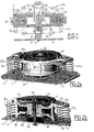
- the mixer shown in FIG. 1 has a base 1 having a flat plate 2 intended to be secured to a structure to calm.
- a coil 20 is secured to this base 1.
- a rod 23 carries at its two ends two flanges 3 and 24, one of which is secured to of the base 1 and the other 24 carries the coil 20.
- the moving part which comprises an upper pole piece 11, a lower pole piece 12 and a magnet 10 is mounted on a spring 22 and is centered by two springs of upper centering 31 and upper 32 mounted on a housing or salad bowl 40.
- the assembly defines an electrodynamic motor whose coil is fixed relative to the base 1 and have the moving part is a mass M b essentially constituted by the magnetic circuit, that is to say the pole pieces 11 and 12 and the magnet 10.
- a control circuit makes it possible to vary the value of a resistive load applied across the coil 20.
- This may be a variable resistance, for example a varistor, the value of which is function voltage, or else a rheostat controlled by the control device.
- We can thus vary the depreciation between two extremes, namely a very low damping by leaving the coil 20 in open circuit, or maximum damping by putting the coil 20 into short circuit, the load resistance then being equal to the component intrinsic resistive Ro of the coil 20.
- a relatively low or minimal damping is appropriate particularly to an aircraft in static flight, for which the vibrations have a established regime for which the drummer is given maximum effect, whereas a greater depreciation can be chosen when changing course to avoid transients that may destabilize the drummer and / or to raise the vibratory level in the cabin.
- the electrical independence coil Z b is connected to a load marked Z c .
- the mass M b is guided by two springs 31 and 32 disposed on either side of the ground circuit M b . They are integral at their center with an axis 23 secured to the base 1 and at their periphery of the ground circuit M b .
- FIG. 3 shows a centering spring 31, 32 made of metal, which has four blanks 50 (or through-holes) which form as many branches which are regularly distributed at 90 ° to the perimeter of an opening 55 and which extend from a internal end 53 near the central opening 55 of diameter D i and up to an outer end 54 near an outer contour 57 of diameter De.
- These cutouts 50 have a rounded profile convex towards the outside of the spring , in particular in the form of a spiral, and preferably of a parabolic spiral.
- the cuts 50 present preferentially a linear section 52 whose function is to avoid stress concentrations as will be explained below.
- the branches 50 form a little more than one turn of the perimeter of the spring between their ends 53 and 54.
- FIG. 4 represents an embodiment with 3 branches whose inner ends 63 are distributed at 90 ° around the periphery of a central opening of diameter Di and which evolve to an end 64 to near the outer contour 67 of diameter De.
- the profile is advantageously spiral, preferably parabolic. It spans a little more than a spring ride.
- a section linear end 62 is advantageously provided to prevent stress concentrations.
- the ends 53, 54, 63, 64 are sufficiently spaced openings 55, 65 and respective contours 57, 67 to allow a good fitting of the spring without concentration of constraints to these ends.
- the springs 31, 32 in the form of a stack of springs for example in the form of a laminated structure that is to say a stack of individual springs secured to each other for example by gluing. This allows you to change the axial stiffness that decreases with the number of layers, as well as the maximum stress reached.
- the preferred embodiment uses cutouts parabolic spiral (or along one or more approximate axes of a circle a spiral parabolic profile).
Abstract
Description
La présente invention a pour objet un dispositif d'amortissement de vibrations.The present invention relates to a device vibration damping.
On utilise dans l'industrie des batteurs dynamiques pour éviter la propagation de vibrations dans une structure donnée.Dynamic drummers are used in the industry to avoid the propagation of vibrations in a given structure.
Ils sont essentiellement basés sur des systèmes masse-ressort, tel que représentés dans le document DE-A- 19 517 630.They are essentially system-based mass-spring, as shown in DE-A-19 517 630.
Dans certaines applications, notamment en aéronautique, et plus particulièrement dans le cas des hélicoptères, il est souhaitable que les performances des batteurs puissent être adaptées en fonction des différentes configurations de vol, et ce à l'aide d'une commande qui rende les caractéristiques du batteur aussi peu dépendantes que possible des conditions de pression, de température et/ou d'hygrométrie.In some applications, notably in aeronautics, and particularly in the case of helicopters, it is desirable that the Drummers' performances can be adapted according to the different flight configurations, using a command that makes the characteristics of the drummer as little dependent as possible of the conditions of pressure, temperature and / or hygrometry.
Selon un premier aspect, l'invention vise à résoudre ce problème, l'idée de base consistant à mettre en oeuvre un moteur électrodynamique dont on fait varier l'amortissement.According to a first aspect, the invention aims to solve this problem. problem, the basic idea of implementing an engine electrodynamics whose damping is varied.
L'invention concerne ainsi un dispositif d'amortissement des vibrations comprenant un dispositif de conversion d'énergie mécanique en énergie électrique monté sur une embase destinée à être fixée sur une structure à calmer, caractérisé en ce que ledit dispositif de conversion comporte un moteur électrodynamique ayant une bobine reliée mécaniquement à l'embase et un circuit magnétique suspendu par au moins un ressort, en ce que la bobine est couplée à une charge électrique présentant une composante résistive et en ce qu'il présente un dispositif de commande pour faire varier la valeur de ladite composante résistive selon au moins deux valeurs.The invention thus relates to a device for damping vibrations comprising a device for converting mechanical energy into electrical energy mounted on a base intended to be fixed on a structure to be calmed, characterized in that said conversion device has an electrodynamic motor having a connected coil mechanically at the base and a magnetic circuit suspended by at least a spring, in that the coil is coupled to an electric charge having a resistive component and having a device for control for varying the value of said resistive component according to minus two values.
La première valeur de commande peut correspondre à un premier amortissement (par exemple en laissant la bobine en circuit ouvert), et la deuxième valeur de commande à un amortissement plus important (par exemple en mettant la bobine en court-circuit). The first command value can correspond to a first damping (for example leaving the coil open), and the second control value at a higher damping (for example by shorting the coil).
L'invention concerne également une utilisation d'un dispositif d'amortissement dans un aéronef, notamment un hélicoptère, caractérisé en ce qu'il met en oeuvre, à l'aide d'un calculateur de vol, une commande du dispositif de commande selon la première valeur de commande lorsque l'aéronef est en vol statique et selon la deuxième valeur de commande lorsque l'aéronef est dans un état de changement de cap.The invention also relates to a use of a device in an aircraft, in particular a helicopter, characterized in that what it implements, using a flight calculator, a command of the control device according to the first command value when the aircraft is in static flight and according to the second command value when the aircraft is in a state of course change.
L'utilisation de batteurs dynamiques pose également le problème du fonctionnement selon une seule direction qui est celle de l'axe de symétrie du système.The use of dynamic drummers also poses the problem of operation in one direction which is that of the axis symmetry of the system.
Le problème posé est ainsi le fait de garantir des déplacements selon cet axe uniquement pour éviter des inconvénients tels que vibrations, parasites, frottements, voir destruction de la bobine.The problem is therefore to guarantee movements along this axis only to avoid disadvantages such that vibrations, parasites, friction, see destruction of the coil.
L'idée de base consistant en une mise en oeuvre d'un ou plusieurs ressorts de centrage appropriés, est réalisée par un dispositif d'amortissement de vibrations comprenant un dispositif de conversion d'énergie monté sur une embase destinée à être fixée sur une structure, le dispositif de conversé d'énergie présentant une partie mobile suspendue par au moins un ressort, la partie mobile présentant au moins un ressort de centrage plat s'étendant entre une région intérieure ayant un premier diamètre et une région extérieure ayant un deuxième diamètre, ledit ressort de centrage présentant au moins deux découpes dont chacune forme une branche ayant au moins un tronçon tournant sa concavité vers l'extérieur du ressort.The basic idea is to implement one or more centering is carried out by a device vibration damping device comprising a conversion device mounted on a base intended to be fixed on a structure, the energy conversation device having a mobile part suspended by at least one spring, the moving part having at least one a flat centering spring extending between an inner region having a first diameter and an outer region having a second diameter, said centering spring having at least two cutouts each of which forms a branch having at least one section turning its concavity outwards spring.
Au moins une découpe peut être au moins en partie en spirale, par exemple en spirale parabolique.At least one cutout may be at least partly spiral, for example spiral parabolic.
Au moins une découpe peut présenter un tronçon externe droit.At least one cutout may have an outer section law.
Chaque découpe fait avantageusement entre 1 et 1,5 tour du périmètre de ressort. Each cut advantageously makes between 1 and 1.5 turns of the perimeter of spring.
Les découpes peuvent être au nombre de 3 et de préférence de 4, et dans ce dernier cas chaque découpe s'étend préférentiellement sur sensiblement un tour du périmètre de ressort.The cuts can be 3 and preferably of 4, and in the latter case each cutout preferably extends over substantially a turn of the spring perimeter.
Il est particulièrement avantageux qu'un ressort de centrage soit constitué d'un empilement de ressorts plats, notamment pour former une structure lamifiée. En effet, la raideur axiale et la contrainte maximale atteinte diminuent avec le nombre de couches empilées, ce qui permet en particulier d'adapter le rapport entre la raideur axiale et la raideur radiale du ressort de centrage. En outre, la contrainte maximale atteinte diminue avec l'épaisseur de chaque couche.It is particularly advantageous that a centering spring consists of a stack of flat springs, in particular to form a laminated structure. Indeed, the axial stiffness and the maximum stress reached decrease with the number of layers stacked, which allows in particular to adapt the ratio between the axial stiffness and the radial stiffness of the spring of centering. In addition, the maximum stress reached decreases with thickness of each layer.
D'autres caractéristiques et avantages de l'invention apparaítront mieux à la lecture de la description qui va suivre, donnée à titre d'exemple non limitatif, en liaison avec les dessins dans lesquels :
- la figure 1 montre une vue schématique en coupe d'un dispositif selon l'invention,
- les figures 2a et 2b représentent respectivement en perspective et ne coupe un dispositif selon un mode de réalisation préféré de l'invention,
- la figure 3 montre une réalisation d'un ressort de centrage ("spider") à trois branches, et
- la figure 4 montre une réalisation d'un ressort de centrage ("spider") à quatre branches.
- FIG. 1 shows a schematic sectional view of a device according to the invention,
- FIGS. 2a and 2b respectively show in perspective and cut a device according to a preferred embodiment of the invention,
- FIG. 3 shows an embodiment of a spider spring with three branches, and
- Figure 4 shows an embodiment of a centering spring ("spider") with four branches.
Le batteur représenté à la figure 1 présente une embase 1
comportant une plaque plane 2 destinée à être solidarisée à une structure à
calmer. Une bobine 20 est solidaire de cette embase 1. A cet effet, une tige
23 porte à ses deux extrémités deux brides 3 et 24 dont l'une 3 est solidaire
de l'embase 1 et dont l'autre 24 porte la bobine 20. La partie mobile qui
comporte une pièce polaire supérieure 11, une pièce polaire inférieure 12 et
un aimant 10 est montée sur un ressort 22 et est centrée par deux ressorts de
centrage supérieur 31 et supérieur 32 montés sur un boítier ou saladier 40.The mixer shown in FIG. 1 has a base 1
having a
On notera au niveau de la bobine 20 l'étanchéité procurée par
le tissu ondulé 26 porté par l'anneau plat 26 monté sur la pièce polaire 11. Note at the level of the
L'ensemble définit un moteur électrodynamique dont la
bobine est fixe par rapport à l'embase 1 et ont la partie mobile est une masse
Mb constituée essentiellement par le circuit magnétique, c'est-à-dire les
pièces polaires 11 et 12 et l'aimant 10.The assembly defines an electrodynamic motor whose coil is fixed relative to the base 1 and have the moving part is a mass M b essentially constituted by the magnetic circuit, that is to say the
Un circuit de commande permet de faire varier la valeur d'une
charge résistive appliquée aux bornes de la bobine 20. Il peut s'agir d'une
résistance variable, par exemple une varistance, dont la valeur est fonction
d'une tension électrique, ou bien encore d'un rhéostat commandé par le
dispositif de commande. On peut faire ainsi varier l'amortissement entre deux
extrêmes, à savoir un amortissement très faible en laissant la bobine 20 en
circuit ouvert, ou un amortissement maximal en mettant la bobine 20 en
court-circuit, la résistance de charge étant alors égale à la composante
résistive intrinsèque Ro de la bobine 20.A control circuit makes it possible to vary the value of a
resistive load applied across the
On peut choisir une valeur d'une résistance de charge plus élevée R1 pour un premier amortissement relativement faible et plus faible R2 pour un amortissement plus important.One can choose a value of a higher load resistance R 1 for a first relatively low damping and lower R 2 for greater damping.
Un amortissement relativement faible ou minimal convient particulièrement à un aéronef en vol statique, pour lequel les vibrations ont un régime établi pour lequel on confère au batteur un effet maximal, alors qu'un amortissement plus important peut être choisi lors d'un changement de cap pour éviter les transitoires susceptibles de déstabiliser le batteur et/ou de faire remonter le niveau vibratoire en cabine.A relatively low or minimal damping is appropriate particularly to an aircraft in static flight, for which the vibrations have a established regime for which the drummer is given maximum effect, whereas a greater depreciation can be chosen when changing course to avoid transients that may destabilize the drummer and / or to raise the vibratory level in the cabin.
Lorsque le batteur fonctionne, un mouvement relatif entre le
circuit magnétique de masse Mb et l'embase 1 existe. La bobine 20 se
comporte donc comme un générateur de force électromotrice Eb = BL v, BL
désignant le facteur de force du moteur électrodynamique (en N/A) et v la
vitesse relative entre le circuit magnétique de masse Mb et l'embase 1.When the mixer is operating, a relative movement between the magnetic ground circuit M b and the base 1 exists. The
On connecte la bobine 20 d'indépendance électrique Zb à une
charge notée Zc. Une force Fa s'établit entre la bobine et le circuit de masse
Mb, qui s'oppose à v (selon la loi de Lenz) et a pour expression :
Nous venons de mettre en évidence l'expression d'une force d'amortissement.We have just highlighted the expression of a force amortization.
Si on suppose que la charge est constituée d'un rhéostat (résistance réglable), nous pouvons alors faire varier le coefficient d'amortissement Cb (Cb = Fa / v) entre 2 valeurs extrêmes.If we assume that the load consists of a rheostat (adjustable resistance), we can then vary the damping coefficient C b (C b = F a / v) between 2 extreme values.
Pour obtenir Cb maximum :
- il faut choisir un moteur électrodynamique dont les caractéristiques permettent de maximiser le rapport (BL)2 / Zb
- Zc doit être minimal (Zc = 0, soit un court-circuit franc)
- you have to choose an electrodynamic motor whose characteristics make it possible to maximize the ratio (BL) 2 / Z b
- Z c must be minimal (Z c = 0, ie a short-circuit)
Pour obtenir Cb minimum :
- il suffit d'ouvrir le circuit électrique (Zc = ∝)
- just open the electrical circuit (Z c = α)
L'accord en fréquence du batteur est donné par la masse
mobile et l'ensemble des raideurs qui lient cette masse à l'embase:
Nous avons alors la relation :
Pour répartir la raideur entre les ressorts de rappel et les
ressorts de centrage 31 et 32, nous considérons les contraintes suivantes :
La contrainte n° 1 impose que le poids statique de la masse mobile Mb soit repris par le(s) ressort(s) 22. Leur longueur à vide est donc calculée pour tenir compte de cette flèche statique, qui s'ajoute au mouvement dynamique : plus la raideur Kr est faible, plus la longueur à vide doit être grande. Il faut donc choisir Kr suffisamment élevé pour que ne se posent pas certaines difficultés d'intégration (encombrement, talonnement des ressorts, spires jointives).Stress No. 1 imposes that the static weight of the moving mass M b is taken up by the spring (s) 22. Their empty length is thus calculated to take account of this static arrow, which is added to the movement dynamic: the lower the Kr stiffness, the longer the empty length must be. It is thus necessary to choose Kr sufficiently high so that do not pose certain difficulties of integration (congestion, talonner of the springs, adjoining turns).
Il n'est pas possible en pratique de faire tendre Ks vers une valeur arbitrairement faible, pour les raisons exposées ci-après.It is not possible in practice to make Ks tend towards a arbitrarily low value, for the reasons given below.
Le batteur décrit fonctionne en une seule direction qui est celle de l'axe de symétrie du système (axe vertical Z sur la figure 1, passant par le centre de la pièce).The drummer described works in one direction which is that of the axis of symmetry of the system (vertical axis Z in FIG. by the center of the room).
Il convient de garantir un mouvement relatif entre le circuit
magnétique de masse Mb et l'embase 1 selon cet axe uniquement afin d'éviter
tout risque de destruction mécanique de la bobine 20.It is necessary to guarantee a relative movement between the magnetic circuit of mass M b and the base 1 along this axis only in order to avoid any risk of mechanical destruction of the
Sont donc exclus a priori :
- les déplacements radiaux (selon les directions X et Y perpendiculaires à la direction Z)
- les rotations selon les axes X et Y
- radial displacements (according to the X and Y directions perpendicular to the Z direction)
- rotations along the X and Y axes
Pour assurer cette fonction, la masse Mb est guidée par deux
ressorts 31 et 32 disposés de part et d'autre du circuit de masse Mb. Ils sont
solidaires en leur centre d'un axe 23 solidaire de l'embase 1 et à leur pourtour
du circuit de masse Mb.To ensure this function, the mass M b is guided by two
Parmi les autres techniques de guidage qui auraient pu être
retenues citons :
La figure 3 représente un ressort de centrage 31, 32 en
métal, qui présente 4 découpes 50 (ou saignées traversantes) qui forment
autant de branches qui sont réparties régulièrement à 90° du périmètre d'une
ouverture 55 et qui s'étendent depuis une extrémité interne 53 à proximité de
l'ouverture centrale 55 de diamètre Di et, jusqu'à une extrémité externe 54 à
proximité d'un contour externe 57 de diamètre De. Ces découpes 50 ont un
profil arrondi convexe vers l'extérieur du ressort, en particulier en forme de
spirale, et de préférence de spirale parabolique.FIG. 3 shows a centering
Vers leur extrémité 54, les découpes 50 présentent
préférentiellement un tronçon linéaire 52 dont la fonction est d'éviter des
concentrations de contraintes ainsi qu'il sera expliqué ci-après. Dans
l'exemple représenté, les branches 50 forment un peu plus d'un tour du
périmètre du ressort entre leurs extrémités 53 et 54.Towards their
La figure 4 représente un mode de réalisation à 3 branches
dont les extrémités internes 63 sont réparties à 90° sur le pourtour d'une
ouverture centrale de diamètre Di et qui évoluent jusqu'à une extrémité 64 à
proximité du contour externe 67 de diamètre De. Comme dans le cas
précédent, le profil est avantageusement en spirale, de préférence
parabolique. Il s'étend sur un peu plus d'un tour du ressort. Un tronçon
d'extrémité linéaire 62 est avantageusement prévu pour éviter des
concentrations de contraintes.FIG. 4 represents an embodiment with 3 branches
whose inner ends 63 are distributed at 90 ° around the periphery of a
central opening of diameter Di and which evolve to an
Les extrémités 53, 54, 63, 64 sont suffisamment espacées
des ouvertures 55, 65 et des contours respectifs 57, 67 pour permettre un
bon encastrement du ressort sans concentration de contraintes à ces
extrémités.The ends 53, 54, 63, 64 are sufficiently spaced
Il est particulièrement avantageux de réaliser les ressorts 31,
32 sous forme d'un empilement de ressorts par exemple sous forme d'une
structure lamifiée c'est-à-dire d'un empilement de ressorts individuels
solidarisés entre eux par exemple par collage. Ceci permet de modifier la
raideur axiale qui diminue avec le nombre de couches, de même que la
contrainte maximale atteinte. It is particularly advantageous to make the
Ceci permet en particulier d'ajuster le rapport entre la raideur axiale et la raideur radiale.This allows in particular to adjust the ratio between the stiffness axial and radial stiffness.
Les avantages des ressorts de centrage 31 et 32 sont les
suivants :
La réalisation des ressorts de centrage 31 et 32 respecte
avantageusement un certain nombre de contraintes :
Le mode de réalisation préféré met en oeuvre des découpes en spirale parabolique (ou selon un ou plusieurs axes de cercle approximant un profil en spirale parabolique).The preferred embodiment uses cutouts parabolic spiral (or along one or more approximate axes of a circle a spiral parabolic profile).
Les paramètres de conception sont :
Claims (5)
- A damper device for damping vibration comprising a converter device for converting mechanical energy into electrical energy that is mounted on a baseplate (2) for fixing to a structure, said converter device comprising an electrodynamic motor having a coil (20) mechanically connected to the baseplate, the device being characterized in that said converter device further comprises a magnetic circuit (10, 11, 12) suspended by at least one spring (22), and in that the coil (20) is coupled to an electrical load presenting a resistive component, and in that it presents a control device (COM) for causing the resistance of said resistive component to vary with at least two values.
- A device according to claim 1, characterized in that the control device (COM) has a first control value for the resistive component corresponding to a first level of damping, and a second control value corresponding to a second level of damping that is greater.
- A device according to claim 2, characterized in that for the first control value, the coil (20) is open circuit.
- A device according to claim 2 or claim 3, characterized in that for the second control value, the coil (20) is short circuit.
- The use of a damper device according to any preceding claim, in an aircraft, in particular in a helicopter, characterized in that it uses a flight computer to cause the control device to take up the first control value when the aircraft is in steady flight and the second control value when the aircraft is in a heading-changing state.
Applications Claiming Priority (3)
| Application Number | Priority Date | Filing Date | Title |
|---|---|---|---|
| FR0107352 | 2001-06-06 | ||
| FR0107352A FR2825769B1 (en) | 2001-06-06 | 2001-06-06 | VIBRATION DAMPING DEVICE |
| PCT/FR2002/001925 WO2002099309A1 (en) | 2001-06-06 | 2002-06-06 | Vibration damping device |
Publications (2)
| Publication Number | Publication Date |
|---|---|
| EP1392987A1 EP1392987A1 (en) | 2004-03-03 |
| EP1392987B1 true EP1392987B1 (en) | 2005-08-03 |
Family
ID=8863977
Family Applications (1)
| Application Number | Title | Priority Date | Filing Date |
|---|---|---|---|
| EP02747509A Expired - Lifetime EP1392987B1 (en) | 2001-06-06 | 2002-06-06 | Vibration damping device |
Country Status (11)
| Country | Link |
|---|---|
| US (1) | US20030173725A1 (en) |
| EP (1) | EP1392987B1 (en) |
| JP (1) | JP2004521290A (en) |
| CN (1) | CN1250889C (en) |
| AT (1) | ATE301254T1 (en) |
| CA (1) | CA2416010A1 (en) |
| DE (1) | DE60205370T2 (en) |
| DK (1) | DK1392987T3 (en) |
| ES (1) | ES2247353T3 (en) |
| FR (1) | FR2825769B1 (en) |
| WO (1) | WO2002099309A1 (en) |
Cited By (1)
| Publication number | Priority date | Publication date | Assignee | Title |
|---|---|---|---|---|
| WO2008131740A1 (en) * | 2007-04-27 | 2008-11-06 | Fraunhofer-Gesellschaft zur Förderung der angewandten Forschung e.V. | Device for damping vibrations |
Families Citing this family (33)
| Publication number | Priority date | Publication date | Assignee | Title |
|---|---|---|---|---|
| FR2856765B1 (en) * | 2003-06-26 | 2005-12-02 | Hutchinson | ACTIVE DYNAMIC BATTERY |
| GB2439411B (en) * | 2007-04-27 | 2008-07-23 | Perpetuum Ltd | An electromechanical generator for converting mechanical vibrational energy into electrical energy |
| CN100564932C (en) * | 2007-05-17 | 2009-12-02 | 中国科学技术大学 | Rigidity-variable full-automatic power vibration-absorber |
| GB2446685B (en) * | 2007-11-27 | 2009-04-01 | Perpetuum Ltd | An electromechanical generator for converting mechanical vibrational energy into electrical energy |
| CA2742798A1 (en) | 2008-11-04 | 2010-05-14 | Lord Corporation | Resonant inertial force generator having stable natural frequency |
| FR2945788B1 (en) * | 2009-05-20 | 2011-05-13 | Eurocopter France | DEVICE WITH MASSES CONCENTRATED TO REDUCE THE VIBRATIONS GENERATED BY A ROTOR OF SUSTENTATION OF A GIRAVION, AND HUB OF A ROTOR PROVIDED WITH SUCH A DEVICE |
| WO2010150385A1 (en) * | 2009-06-25 | 2010-12-29 | パイオニア株式会社 | Vibration damper and damping mechanism |
| EP2915745B1 (en) * | 2009-11-04 | 2017-12-13 | LORD Corporation | Electromagnetic inertial actuator |
| WO2011056257A1 (en) | 2009-11-04 | 2011-05-12 | Lord Corporation | Electromagnetic inertial actuator |
| US8188622B1 (en) * | 2009-11-12 | 2012-05-29 | The United States Of America, As Represented By The Secretary Of The Navy | Tunable resonant frequency kinetic energy harvester |
| CN102858590B (en) | 2009-11-20 | 2015-09-30 | 哥伦比亚国防部空军 | Shock attenuation unit in helicopter flight person's seat |
| CN102011822B (en) * | 2010-10-20 | 2013-03-20 | 哈尔滨工程大学 | Hybrid vibration isolator |
| KR101911000B1 (en) | 2011-02-04 | 2018-10-23 | 로오드 코포레이션 | Rotary wing aircraft vibration control system with resonant inertial actuators |
| DE102011106127A1 (en) | 2011-06-10 | 2012-12-13 | Eads Deutschland Gmbh | Device for reducing structural vibrations of airfoils |
| DK2745028T3 (en) * | 2011-08-18 | 2015-11-23 | Esm En Und Schwingungstechnik Mitsch Gmbh | TEMPERATURE RELEASED VIBRATION DIMENSIONS |
| JP5863528B2 (en) | 2012-03-23 | 2016-02-16 | 三菱重工業株式会社 | Vibration reduction device |
| CN102733483A (en) * | 2012-07-02 | 2012-10-17 | 大连理工大学 | Variable rigidity shock insulation integral intelligent support seat |
| JP6060621B2 (en) * | 2012-10-29 | 2017-01-18 | ミツミ電機株式会社 | Power generation device and power generation system |
| JP2014093841A (en) * | 2012-11-02 | 2014-05-19 | Mitsumi Electric Co Ltd | Power generation device |
| CN103016587B (en) * | 2012-12-12 | 2015-04-01 | 上海交通大学 | Semi-driving type variable stiffness dynamic vibration absorber made from conical springs |
| KR101437363B1 (en) | 2013-01-07 | 2014-09-15 | 한국기계연구원 | Damper and generator damper |
| EP2857313B1 (en) * | 2013-10-03 | 2015-12-23 | AGUSTAWESTLAND S.p.A. | Hover aircraft rotor comprising a vibration damping device |
| CN103629302B (en) * | 2013-11-29 | 2015-10-28 | 东风小康汽车有限公司重庆分公司 | Inner balance flywheel |
| DE102013113347A1 (en) * | 2013-12-02 | 2015-06-03 | Airbus Defence and Space GmbH | Inertialkraftgenerator with integrated holding mechanism |
| CN105912044B (en) * | 2016-06-06 | 2018-08-03 | 上海交通大学 | Frequency resolution is tunable dynamic vibration absorber |
| CN107504125A (en) * | 2017-09-23 | 2017-12-22 | 无锡工艺职业技术学院 | A kind of plant equipment damping device |
| TWI650627B (en) * | 2017-10-27 | 2019-02-11 | 逢甲大學 | PTZ damping system |
| RU180588U1 (en) * | 2017-11-14 | 2018-06-19 | Федеральное государственное казенное военное образовательное учреждение высшего профессионального образования "Военная академия материально-технического обеспечения имени генерала армии А.В. Хрулёва" Министерства обороны Российской Федерации | Advanced tuning fork vibro-thermal sensor |
| CN108488552A (en) * | 2018-03-30 | 2018-09-04 | 王宏伟 | A kind of novel mechanical equipment damping base |
| US10899437B2 (en) * | 2018-04-24 | 2021-01-26 | Bell Helicopter Textron Inc. | Planar vibration isolator |
| CN112610635A (en) * | 2021-01-25 | 2021-04-06 | 深圳市佳键合科技有限公司 | Damping device capable of automatically adjusting damping stroke according to vibration intensity |
| CN113048191B (en) * | 2021-03-11 | 2022-07-15 | 哈尔滨工程大学 | Three-dimensional low-frequency broadband seismic metamaterial tree based on tree bionics |
| CN114033833B (en) * | 2021-11-29 | 2023-01-17 | 中国人民解放军海军工程大学 | Parameter-adjustable high-static-low dynamic stiffness electromagnetic vibration isolator |
Family Cites Families (6)
| Publication number | Priority date | Publication date | Assignee | Title |
|---|---|---|---|---|
| US5293969A (en) * | 1991-02-14 | 1994-03-15 | Atsugi Unisia Corporation | Electromagnetic suspension device |
| FR2680848B1 (en) * | 1991-08-29 | 1995-03-17 | Aerospatiale Ste Nat Indle | METHOD AND DEVICE FOR FILTERING THE VIBRATORY EXCITATIONS TRANSMITTED BETWEEN TWO PARTS, IN PARTICULAR BETWEEN THE ROTOR AND THE FUSELAGE OF A HELICOPTER. |
| DE19517630C2 (en) * | 1995-05-13 | 1997-10-09 | Metzeler Gimetall Ag | Active vibration absorber |
| DE19621700C2 (en) * | 1996-05-30 | 2001-09-27 | Eurocopter Deutschland | Active vibration reducer |
| JP2000274482A (en) * | 1999-01-18 | 2000-10-03 | Canon Inc | Active vibration resistant device, exposure device and method, and manufacture of device |
| FR2825768B1 (en) * | 2001-06-06 | 2004-03-12 | Vibrachoc Sa | VIBRATION DAMPING DEVICE |
-
2001
- 2001-06-06 FR FR0107352A patent/FR2825769B1/en not_active Expired - Fee Related
-
2002
- 2002-06-06 DE DE60205370T patent/DE60205370T2/en not_active Expired - Lifetime
- 2002-06-06 JP JP2003502396A patent/JP2004521290A/en active Pending
- 2002-06-06 AT AT02747509T patent/ATE301254T1/en not_active IP Right Cessation
- 2002-06-06 EP EP02747509A patent/EP1392987B1/en not_active Expired - Lifetime
- 2002-06-06 WO PCT/FR2002/001925 patent/WO2002099309A1/en active IP Right Grant
- 2002-06-06 DK DK02747509T patent/DK1392987T3/en active
- 2002-06-06 US US10/333,089 patent/US20030173725A1/en not_active Abandoned
- 2002-06-06 CA CA002416010A patent/CA2416010A1/en not_active Abandoned
- 2002-06-06 CN CN02801960.1A patent/CN1250889C/en not_active Expired - Fee Related
- 2002-06-06 ES ES02747509T patent/ES2247353T3/en not_active Expired - Lifetime
Cited By (2)
| Publication number | Priority date | Publication date | Assignee | Title |
|---|---|---|---|---|
| WO2008131740A1 (en) * | 2007-04-27 | 2008-11-06 | Fraunhofer-Gesellschaft zur Förderung der angewandten Forschung e.V. | Device for damping vibrations |
| US8708115B2 (en) | 2007-04-27 | 2014-04-29 | Fraunhofer-Gesellschaft Zur Foerderung Der Angewandten Forschung E.V. | Device for damping vibrations |
Also Published As
| Publication number | Publication date |
|---|---|
| FR2825769B1 (en) | 2004-08-27 |
| DE60205370T2 (en) | 2006-06-01 |
| CN1463338A (en) | 2003-12-24 |
| US20030173725A1 (en) | 2003-09-18 |
| ATE301254T1 (en) | 2005-08-15 |
| DK1392987T3 (en) | 2005-12-05 |
| DE60205370D1 (en) | 2005-09-08 |
| FR2825769A1 (en) | 2002-12-13 |
| JP2004521290A (en) | 2004-07-15 |
| ES2247353T3 (en) | 2006-03-01 |
| EP1392987A1 (en) | 2004-03-03 |
| CA2416010A1 (en) | 2002-12-12 |
| WO2002099309A1 (en) | 2002-12-12 |
| CN1250889C (en) | 2006-04-12 |
Similar Documents
| Publication | Publication Date | Title |
|---|---|---|
| EP1392987B1 (en) | Vibration damping device | |
| EP1315917B1 (en) | Vibration damping device | |
| EP2256039B1 (en) | Through-pivot with flexible elements and spacecraft comprising such a pivot | |
| FR2770826A1 (en) | Rotor blade construction | |
| EP2503641B1 (en) | Actuating system for antenna reflector with deformable reflecting surface | |
| FR2850217A1 (en) | PIEZOACTIVE ACTUATOR WITH AMPLIFIED MOVEMENT | |
| EP2018601A2 (en) | Spiral/collet assembly for a horological movement | |
| FR2959547A1 (en) | DECOUPLING PULLEY. | |
| EP0608675B1 (en) | High rotating speed, high power electrical motor | |
| FR3046436A1 (en) | ELECTROSTATIC CONVERTER. | |
| WO2017072338A1 (en) | Vibration damper | |
| WO2017072337A1 (en) | Vibration damper, associated damping mechanism and propulsion assembly | |
| EP2724945A2 (en) | Motorisation system for articulation with flexible roller tracks | |
| WO2020025343A1 (en) | Variable spacing flange pulley for variable-speed drive | |
| BE1022436B1 (en) | WIND ROTOR OF SAVONIUS TYPE | |
| WO2013045850A1 (en) | Coiled electronic power component comprising a heat sinking support | |
| EP0090703B1 (en) | Protection device for a high-frequency, high-power variable inductance | |
| FR3057927A1 (en) | TORSION DAMPER AND MOTOR VEHICLE | |
| FR2809150A1 (en) | Damper used between the IC engine and the gearbox of a car has compression spring and elastic element mounted in series between a entry element and an exit element | |
| WO2006045970A1 (en) | Alternator provided with a vibration damping device | |
| FR2658365A1 (en) | SPRING OF THE CONICAL TYPE FOR ELECTRICAL CONTACT. | |
| WO2021038005A1 (en) | Torque transmission device | |
| WO2021005284A1 (en) | Robotic traction module | |
| FR3072146A1 (en) | HUB FOR SHOCKWHEEL FOR MOTOR VEHICLE | |
| EP3712463A1 (en) | Damping device |
Legal Events
| Date | Code | Title | Description |
|---|---|---|---|
| PUAI | Public reference made under article 153(3) epc to a published international application that has entered the european phase |
Free format text: ORIGINAL CODE: 0009012 |
|
| 17P | Request for examination filed |
Effective date: 20021223 |
|
| AK | Designated contracting states |
Kind code of ref document: A1 Designated state(s): AT BE CH CY DE DK ES FI FR GB GR IE IT LI LU MC NL PT SE TR |
|
| AX | Request for extension of the european patent |
Extension state: AL LT LV MK RO SI |
|
| RIN1 | Information on inventor provided before grant (corrected) |
Inventor name: NOE, MATHIEU |
|
| GRAP | Despatch of communication of intention to grant a patent |
Free format text: ORIGINAL CODE: EPIDOSNIGR1 |
|
| GRAS | Grant fee paid |
Free format text: ORIGINAL CODE: EPIDOSNIGR3 |
|
| GRAA | (expected) grant |
Free format text: ORIGINAL CODE: 0009210 |
|
| AK | Designated contracting states |
Kind code of ref document: B1 Designated state(s): AT BE CH CY DE DK ES FI FR GB GR IE IT LI LU MC NL PT SE TR |
|
| PG25 | Lapsed in a contracting state [announced via postgrant information from national office to epo] |
Ref country code: TR Free format text: LAPSE BECAUSE OF FAILURE TO SUBMIT A TRANSLATION OF THE DESCRIPTION OR TO PAY THE FEE WITHIN THE PRESCRIBED TIME-LIMIT Effective date: 20050803 Ref country code: IE Free format text: LAPSE BECAUSE OF FAILURE TO SUBMIT A TRANSLATION OF THE DESCRIPTION OR TO PAY THE FEE WITHIN THE PRESCRIBED TIME-LIMIT Effective date: 20050803 Ref country code: NL Free format text: LAPSE BECAUSE OF FAILURE TO SUBMIT A TRANSLATION OF THE DESCRIPTION OR TO PAY THE FEE WITHIN THE PRESCRIBED TIME-LIMIT Effective date: 20050803 Ref country code: AT Free format text: LAPSE BECAUSE OF FAILURE TO SUBMIT A TRANSLATION OF THE DESCRIPTION OR TO PAY THE FEE WITHIN THE PRESCRIBED TIME-LIMIT Effective date: 20050803 |
|
| REG | Reference to a national code |
Ref country code: GB Ref legal event code: FG4D Free format text: NOT ENGLISH |
|
| REG | Reference to a national code |
Ref country code: CH Ref legal event code: EP |
|
| REG | Reference to a national code |
Ref country code: IE Ref legal event code: FG4D Free format text: LANGUAGE OF EP DOCUMENT: FRENCH |
|
| REF | Corresponds to: |
Ref document number: 60205370 Country of ref document: DE Date of ref document: 20050908 Kind code of ref document: P |
|
| REG | Reference to a national code |
Ref country code: CH Ref legal event code: NV Representative=s name: ISLER & PEDRAZZINI AG |
|
| REG | Reference to a national code |
Ref country code: SE Ref legal event code: TRGR |
|
| GBT | Gb: translation of ep patent filed (gb section 77(6)(a)/1977) |
Effective date: 20051028 |
|
| REG | Reference to a national code |
Ref country code: DK Ref legal event code: T3 |
|
| REG | Reference to a national code |
Ref country code: GR Ref legal event code: EP Ref document number: 20050403329 Country of ref document: GR |
|
| PG25 | Lapsed in a contracting state [announced via postgrant information from national office to epo] |
Ref country code: PT Free format text: LAPSE BECAUSE OF FAILURE TO SUBMIT A TRANSLATION OF THE DESCRIPTION OR TO PAY THE FEE WITHIN THE PRESCRIBED TIME-LIMIT Effective date: 20060103 |
|
| NLV1 | Nl: lapsed or annulled due to failure to fulfill the requirements of art. 29p and 29m of the patents act | ||
| REG | Reference to a national code |
Ref country code: ES Ref legal event code: FG2A Ref document number: 2247353 Country of ref document: ES Kind code of ref document: T3 |
|
| REG | Reference to a national code |
Ref country code: IE Ref legal event code: FD4D |
|
| PLBE | No opposition filed within time limit |
Free format text: ORIGINAL CODE: 0009261 |
|
| STAA | Information on the status of an ep patent application or granted ep patent |
Free format text: STATUS: NO OPPOSITION FILED WITHIN TIME LIMIT |
|
| PG25 | Lapsed in a contracting state [announced via postgrant information from national office to epo] |
Ref country code: MC Free format text: LAPSE BECAUSE OF NON-PAYMENT OF DUE FEES Effective date: 20060630 |
|
| 26N | No opposition filed |
Effective date: 20060504 |
|
| REG | Reference to a national code |
Ref country code: CH Ref legal event code: PCAR Free format text: ISLER & PEDRAZZINI AG;POSTFACH 1772;8027 ZUERICH (CH) |
|
| PG25 | Lapsed in a contracting state [announced via postgrant information from national office to epo] |
Ref country code: CY Free format text: LAPSE BECAUSE OF FAILURE TO SUBMIT A TRANSLATION OF THE DESCRIPTION OR TO PAY THE FEE WITHIN THE PRESCRIBED TIME-LIMIT Effective date: 20050803 |
|
| PGFP | Annual fee paid to national office [announced via postgrant information from national office to epo] |
Ref country code: DK Payment date: 20090625 Year of fee payment: 8 |
|
| PGFP | Annual fee paid to national office [announced via postgrant information from national office to epo] |
Ref country code: FI Payment date: 20090615 Year of fee payment: 8 Ref country code: LU Payment date: 20090612 Year of fee payment: 8 Ref country code: SE Payment date: 20090618 Year of fee payment: 8 |
|
| PGFP | Annual fee paid to national office [announced via postgrant information from national office to epo] |
Ref country code: CH Payment date: 20090617 Year of fee payment: 8 |
|
| PGFP | Annual fee paid to national office [announced via postgrant information from national office to epo] |
Ref country code: GR Payment date: 20090430 Year of fee payment: 8 |
|
| PGFP | Annual fee paid to national office [announced via postgrant information from national office to epo] |
Ref country code: BE Payment date: 20090715 Year of fee payment: 8 |
|
| BERE | Be: lapsed |
Owner name: *HUTCHINSON Effective date: 20100630 |
|
| PG25 | Lapsed in a contracting state [announced via postgrant information from national office to epo] |
Ref country code: FI Free format text: LAPSE BECAUSE OF NON-PAYMENT OF DUE FEES Effective date: 20100606 |
|
| REG | Reference to a national code |
Ref country code: DK Ref legal event code: EBP Ref country code: CH Ref legal event code: PL |
|
| EUG | Se: european patent has lapsed | ||
| PG25 | Lapsed in a contracting state [announced via postgrant information from national office to epo] |
Ref country code: CH Free format text: LAPSE BECAUSE OF NON-PAYMENT OF DUE FEES Effective date: 20100630 Ref country code: LI Free format text: LAPSE BECAUSE OF NON-PAYMENT OF DUE FEES Effective date: 20100630 |
|
| PG25 | Lapsed in a contracting state [announced via postgrant information from national office to epo] |
Ref country code: BE Free format text: LAPSE BECAUSE OF NON-PAYMENT OF DUE FEES Effective date: 20100630 Ref country code: GR Free format text: LAPSE BECAUSE OF NON-PAYMENT OF DUE FEES Effective date: 20110104 |
|
| PG25 | Lapsed in a contracting state [announced via postgrant information from national office to epo] |
Ref country code: DK Free format text: LAPSE BECAUSE OF NON-PAYMENT OF DUE FEES Effective date: 20100630 |
|
| PG25 | Lapsed in a contracting state [announced via postgrant information from national office to epo] |
Ref country code: SE Free format text: LAPSE BECAUSE OF NON-PAYMENT OF DUE FEES Effective date: 20100607 Ref country code: LU Free format text: LAPSE BECAUSE OF NON-PAYMENT OF DUE FEES Effective date: 20100606 |
|
| REG | Reference to a national code |
Ref country code: FR Ref legal event code: PLFP Year of fee payment: 14 |
|
| REG | Reference to a national code |
Ref country code: GR Ref legal event code: ML Ref document number: 20050403329 Country of ref document: GR Effective date: 20110104 |
|
| REG | Reference to a national code |
Ref country code: FR Ref legal event code: PLFP Year of fee payment: 15 |
|
| REG | Reference to a national code |
Ref country code: FR Ref legal event code: PLFP Year of fee payment: 16 |
|
| PGFP | Annual fee paid to national office [announced via postgrant information from national office to epo] |
Ref country code: DE Payment date: 20170621 Year of fee payment: 16 Ref country code: FR Payment date: 20170505 Year of fee payment: 16 Ref country code: GB Payment date: 20170620 Year of fee payment: 16 |
|
| PGFP | Annual fee paid to national office [announced via postgrant information from national office to epo] |
Ref country code: IT Payment date: 20170622 Year of fee payment: 16 |
|
| PGFP | Annual fee paid to national office [announced via postgrant information from national office to epo] |
Ref country code: ES Payment date: 20170724 Year of fee payment: 16 |
|
| REG | Reference to a national code |
Ref country code: DE Ref legal event code: R119 Ref document number: 60205370 Country of ref document: DE |
|
| GBPC | Gb: european patent ceased through non-payment of renewal fee |
Effective date: 20180606 |
|
| PG25 | Lapsed in a contracting state [announced via postgrant information from national office to epo] |
Ref country code: DE Free format text: LAPSE BECAUSE OF NON-PAYMENT OF DUE FEES Effective date: 20190101 Ref country code: IT Free format text: LAPSE BECAUSE OF NON-PAYMENT OF DUE FEES Effective date: 20180606 Ref country code: GB Free format text: LAPSE BECAUSE OF NON-PAYMENT OF DUE FEES Effective date: 20180606 Ref country code: FR Free format text: LAPSE BECAUSE OF NON-PAYMENT OF DUE FEES Effective date: 20180630 |
|
| REG | Reference to a national code |
Ref country code: ES Ref legal event code: FD2A Effective date: 20190916 |
|
| PG25 | Lapsed in a contracting state [announced via postgrant information from national office to epo] |
Ref country code: ES Free format text: LAPSE BECAUSE OF NON-PAYMENT OF DUE FEES Effective date: 20180607 |