EP1392913B1 - Method and apparatus for recovering fibre and fibre-based solids from a filtrate of the mechanical or chemi-mechanical wood pulp industry, said filtrate containing both solids and lipophilic extractive material - Google Patents
Method and apparatus for recovering fibre and fibre-based solids from a filtrate of the mechanical or chemi-mechanical wood pulp industry, said filtrate containing both solids and lipophilic extractive material Download PDFInfo
- Publication number
- EP1392913B1 EP1392913B1 EP02722318A EP02722318A EP1392913B1 EP 1392913 B1 EP1392913 B1 EP 1392913B1 EP 02722318 A EP02722318 A EP 02722318A EP 02722318 A EP02722318 A EP 02722318A EP 1392913 B1 EP1392913 B1 EP 1392913B1
- Authority
- EP
- European Patent Office
- Prior art keywords
- filtrate
- fibre
- centrifuge
- solids
- pulp
- Prior art date
- Legal status (The legal status is an assumption and is not a legal conclusion. Google has not performed a legal analysis and makes no representation as to the accuracy of the status listed.)
- Expired - Lifetime
Links
Images


Classifications
-
- D—TEXTILES; PAPER
- D21—PAPER-MAKING; PRODUCTION OF CELLULOSE
- D21F—PAPER-MAKING MACHINES; METHODS OF PRODUCING PAPER THEREON
- D21F1/00—Wet end of machines for making continuous webs of paper
- D21F1/66—Pulp catching, de-watering, or recovering; Re-use of pulp-water
-
- D—TEXTILES; PAPER
- D21—PAPER-MAKING; PRODUCTION OF CELLULOSE
- D21C—PRODUCTION OF CELLULOSE BY REMOVING NON-CELLULOSE SUBSTANCES FROM CELLULOSE-CONTAINING MATERIALS; REGENERATION OF PULPING LIQUORS; APPARATUS THEREFOR
- D21C5/00—Other processes for obtaining cellulose, e.g. cooking cotton linters ; Processes characterised by the choice of cellulose-containing starting materials
Definitions
- the present invention relates to a method and apparatus for recovering fibre and fibre-based solids from filtrates containing both solids and lipophilic extractive agents, i.e. extractives of the mechanical or chemi-mechanical pulp industry.
- Lipophilic extractives i.e. mainly resin from wood, cause various problems particularly in the production of pulp and paper from mechanical or chemi-mechanical pulp. The most common problems are fouling of wires and showers, and deposits at the paper machine. Lipophilic extractives and their deposits also decrease the strength and brightness properties of the paper and cause holes in the paper.
- TMP ThermoMechanical Pulping
- CTMP ChemiThermoMechanical Pulping
- GW GroundWood
- PGW Pressure GroundWood
- APMP Alkaline Peroxide Mechanical Pulping
- CMP ChemiMechanical Pulping
- Modifying the water circulations and the use of more efficient washing equipment means in practice increasing the loss of solids multifold compared with the present situation. Modifying the water circulations alone would increase the solids loss to be even 4-5 fold compared with the present. More efficient presses in the wash of lipophilic extractives would increase the solids loss even from this up to 3-6 fold. Further, more efficient presses separate from the pulp to the water fine solids, which would have a clearly improving influence on the optic properties in the paper to be produced. Thus, if the filtrate from this press was removed from the process, the optic properties of the pulp would deteriorate. Changing the water circulations and employing more efficient presses presuppose development of more efficient fibre recovering equipment and introducing them into use.
- a PGW (Pressure Ground Wood) process Fig. 1
- the wood is introduced into the process as logs which are then ground at 2 at a high pressure to a fibre suspension.
- the thickening device 4 is called a hot loop thickener.
- the consistency of the fibre suspension is raised by removing from it filtrate, which is introduced into a hot water tank 6. Part of the filtrate in question is pumped from the hot water tank 6 to serve as shower water in refining while the rest flows into a channel 8 and further to the water cleaning system of the mill.
- the fibre suspension thickened in the hot loop thickener 4 is then introduced into sorting 10, however, before that the suspension is diluted, 12, with liquid obtained at least partly from the process itself.
- sorting 10 the fibre suspension continues to a disc filter 14, which again removes liquid/filtrate from the suspension.
- Filtrates of two types are obtained from the disc filter 14 by conventional methods, i. e. a clear filtrate and a cloudy filtrate, each into its own filtrate tank 16 and 18. Sometimes also a so-called super clear filtrate is separated which practically does not contain fines at all.
- the thickened fibre suspension flows to a bleach press 20 with which the consistency of the suspension is raised to the level required by the bleaching process. Filtrate from the bleach press 20 is collected to a bleach press filtrate tank 22 and from there in most cases all of it is used in the dilution 24 preceding the disc filter 14.
- the thickened fibre suspension from the bleach press 20 flows to a bleaching 26 (peroxide bleaching in the figure), which is followed by a washing press 28, which aims at removing reaction products of the bleaching from the fibre suspension. After the washing press 28 the suspension travels to the paper mill while the filtrate from the washing press 28 flows to a washing press filtrate tank 30.
- the filtrate collected there is used with filtrate from the bleach press 20 in the dilution 24 preceding the disc filter 14 and with fresh water in a dilution 32 preceding the washing press 28. It should be noted from the above description that the several dilution and the following pressing and thickening stages mentioned above mean in practice washing the fibre suspension whereby extractives or other substances detached from the fibres during the process and intended to be removed, are washed from the suspension.
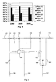
- Table I presents extractive and solids contents of various filtrates in a prior art process ( Fig. 1 ) and Table II illustrates solids contents and extractives retentions of various filtrates from prior art presses Table I.
- fibre recovery is usually not employed, or if it is, the fibre recovery is based on screening and filtering methods or flotation. Problems with these methods are for example: the low consistency of the recovered solids, the retention of lipophilic extractives into the solids to be recovered and/or the poor solids recovery degree. The problems in the separation are mostly due to the high fines content in the filtrate, the size of the lipophilic extractives is approx. 0.1 - 2 ⁇ m and the size of the fibre material >5 ⁇ m which means that the filtering must employ a small hole size.
- the result achievable with the present fibre recovery methods is a compromise between the volume of the recovered fibres and the extractives load recycled to the process.
- Table III presents results obtained with various fibre recovery apparatus.
- Table III. Method Solids recovery degree % Extractives returned % Discharge consistency % Operation principle of separation method Disc thickener 90-95 20-50 10-20 filtering through pulp cake Flotation 85-98 30-55 1 - 15 20 - 80 ⁇ m air bubble Micro screen 30-60 10-15 ⁇ 1 screen plate with hole size 20-150 ⁇ m Certus microfilter ⁇ 100 93-99 * ceramic filter with hole size 1 ⁇ m Decanter centrifuge >85 ⁇ 0 25-30 settling based on centrifugal force *discharge consistency not given
- the most common fibre recovering apparatus are disc and drum thickeners in which the fibre and the fines are filtered through a solids cake as completely as possible. This method gives a fairly high solids recovery degree but at the same time the solids cake filters efficiently also colloidal substances off from the water. If the thickness of the solids cake is decreased the retention of colloids decreases but also the solids recovery efficiency decreases.
- the flotation method gives a high degree of solids recovery.
- air bubbles remove also colloidal material with the solids.
- a drawback of a flotator is the low consistency of the recovered material and the large share of the colloidal detrimental material returning to the process.
- US-A- 5,468,396 discusses the treating of the process liquids of pulp and paper industry by means of a conventional centrifuge to remove from the liquids contaminants less dense than water, like resins.
- the document teaches how the filtrates of kraft pulping, for instance, are divided into three fractions in an ordinary centrifuge, the fractions being the light contaminants, purified liquid, and heavier contaminants, like fibers and fines.
- the specification teaches further that it would be advantageous to reduce the amount of fibers and fines in the liquid entering the centrifuge by means of a filter upstream of the centrifuge.
- the specification teaches how the heavier contaminants are discharged from the apparatus intermittently via valves, which are opened for a short period.
- the apparatus of the US document is not purposed to continuous recovery of fibers from filtrates but rather to remove contaminants less dense than water from the, preferably, prefiltered filtrate.
- a method of continuously recovering both fibre and fibre-based solids from a filtrate, said filtrate of the mechanical or chemi-mechanical wood pulp processing industry containing both solids and colloidal lipophilic extractive material comprising the steps of a. transporting said filtrate to a centrifuge developing a strong central acceleration, said centrifuge being either a decanter centrifuge or a screen bowl centrifuge; b.
- said centrifuge separating the filtrate into two fractions, namely a liquid fraction containing the colloidal lipophilic extractives and a further fraction containing said fibre and fibre-based solids, the strong central acceleration generated in said centrifuge being such that, said further fraction containing said fibre and fibre-based solids settles onto an inner surface of said centrifuge; c. mechanically discharging said separated further fraction containing fibre and fibre-based solids from said centrifuge with the help of a screw conveyor arranged within said centrifuge; and d. removing the liquid fraction from said centrifuge as a separate flow.
- an apparatus for use in the mechanical and chemi-mechanical wood pulp processing industry comprising a device for separating a filtrate from mechanical or chemi-mechanical pulp, the filtrate containing both solids and colloidal lipophilic extractives, and a centrifuge for continuously recovering said fibre and fibre-based solids from the filtrate, wherein the centrifuge is either a decanter centrifuge or a screen bowl centrifuge, said centrifuge separating the filtrate into two fractions, namely a liquid fraction containing the colloidal lipophilic extractives and a further fraction containing said fibre and fibre-based solids, by generating a strong central acceleration in such a way that said further fraction containing said fibre and fibre-based solids settles onto an inner surface of said centrifuge, and wherein said further fraction containing said fibre and fibre-based solids is mechanically discharged from said centrifuge with the help of a screw conveyor arranged within said centrifuge and said liquid fraction is removed from said centr
- Centrifuging means a sorting or a separation process based on the centrifugal force.
- the centrifugal force created in the centrifuging has the same kind of an effect on material as the gravitational force in settling.
- the centrifugal force created in the centrifuging is hundreds or thousands of times stronger than the gravitational force; therefore centrifuging
- Fig. 2a is a schematic illustration of a centrifuge which is composed of a cylinder 40 to be rotated at a high speed and having a closed wall. The centrifugal force separates from the material supplied into the cylinder 40 the heavy fraction against the wall of the cylinder to a dense layer 42 while the liquid and the lighter material remain as layers 44 of their own on top of the solid material layer.
- Filtering centrifuges in turn are, in a way, combinations of filtering devices and centrifuges ( Fig. 2b ).
- filtering centrifuges the separation of particles itself takes place by filtering.
- the starting point of the filtering centrifuges as well is a rotating cylinder 50, but unlike a sedimentation centrifuge, it has a porous surface provided with holes, slots or other apertures suitable for the purpose.
- the driving force in the filtering is, however, the hydrostatic pressure created by the centrifugal force, which is why the methods are classified in separation methods based on centrifuging.
- the heavy material is accumulated onto the surface, in this case the perforated surface, of the cylinder and the lighter material closer to the axis of the cylinder.
- the liquid is removed via the apertures in the cylinder 50 and the extractives retain into the solid material layer.
- particles are separated by means of the centrifugal force as in the sedimentation centrifuging.
- the combination apparatus additionally comprise a washing/thickening zone which functions according to the same principle as a filtering centrifuge.
- the method must be continuous as the processes of the industry in this field are continuous and the liquid volumes to be treated are large. Batchtype operation is out of the question.
- the capacity must be high, at least ten litres per second.
- the method must be applicable in the treatment of sludges and suspensions. Also long-fibre suspensions are treated which further raises the requirements set on the apparatus.
- the fibre recovery degree must be high as the fibre is valuable paper manufacture raw material, which cannot be wasted.
- significant extractives retention is not acceptable, either, as expressly a solution is sought by means of which the problems caused by extractives could be avoided in the manufacture of both pulp and paper.
- the apparatus should be able to reach a high final consistency so as not to have to recycle the fibre returned from the apparatus for reuse back to the process via a thickener.
- the decanter centrifuge 60 illustrated in Fig. 3 and discussed for example in patent publication EP-A1-447742 comprises an outer casing 62, which surrounds the rotating parts of the device and comprises discharge outlets 64 and 66 for the thickened material and the filtrate.
- an outer casing 62 which surrounds the rotating parts of the device and comprises discharge outlets 64 and 66 for the thickened material and the filtrate.
- Inside the outer shell there is a rotating bowl 68, one end 70 of which is in this structure conical and the other end 72 cylindrical.
- Each end of the bowl has been provided with discharge openings 74 and 76. These are located at the end 72 of the bowl 68 having a larger diameter in the end plate 78 of the bowl 68, and at the narrower end 70 directly along the periphery of the casing of the bowl 68.
- the bowl 68 has been supported with bearings 80 at both the ends.
- a screw conveyor 82 has been placed inside the bowl 68, the screw thread of which extends close to the inner wall of the bowl 68.
- the screw conveyor 82 and the bowl 68 have been connected to each other via gears 86 so that a small difference is created between the rotation speed of the screw conveyor 82 and that of the bowl 68.
- the purpose of this difference is to force the screw conveyor 82 to feed the solids separated by the centrifugal force onto the inner surface of the bowl 68 towards the outlet 74 at the narrower end 70 of the bowl 68.
- the decanter centrifuge illustrated in the figure works so that the suspension to be treated is supplied via the pipe 88 to the screw conveyor 82, which rotates at a high speed. From there the liquid shoots out due to the centrifugal force created by the high rotational speed via holes 92 into the bowl 68 and there, further due to the centrifugal force, the heavy solids are separated from the liquid onto the surface of the bowl 68 while the liquid, being lighter, remains further inside.
- the screw conveyor 82 rotating inside the bowl 68 scrapes with it solid material from the surface of the bowl 68 towards the narrower end 70 of the bowl and from there towards the outlet 74 while the liquid flows to the opposite direction, in other words to a direction where the liquid gets further away from the center line of the rotating bowl 68.
- the thickness of the liquid layer in the bowl 68 is determined by the liquid outlets 76, or rather their distance from the inner surface of the bowl 68.
- the liquid is discharged from the bowl via the opposite end compared with the solids.
- other clearly lighter solid material such as in the case of the invention the extractive material particles, are removed with the liquid. In this way the separated fractions are discharged from the apparatus each via their own outlets 64 and 66.
- Decanter centrifuges have been disclosed also in Swedish patent publications 509400 and 501213 .
- the basic operation principles of the solutions disclosed in these are of course the same as that of the centrifuge illustrated in Fig. 3 . Only for example the feed point of the liquid to be treated may vary which results in a little different flow directions of the fractions in the apparatus.
- the screen bowl centrifuge illustrated in Fig. 4 and disclosed in US patent no. 5,321,898 works in principle in the same way. In other words the division of the liquid into fractions is performed with a uniform, non-perforated rotating surface. The only more significant difference is that in the separation portion 96, into which in practise flows only solids separated from the liquid, there is a screen surface 97 through which the finer fraction of the solids is removed from the apparatus to a discharge hopper 98. The coarser fraction of the solids is discharged via the end of the apparatus to a discharge chute 99. This portion may also be called a solids washing portion.
- the solving of the problems the invention addresses can be started with an apparatus, the characteristic features of which are both that the liquid is divided into fractions by a revolving unbroken surface, and that the revolving speed of the apparatus, more precisely that of the bowl or the cylinder of the apparatus, is high.
- the central acceleration the apparatus develops we have determined it in our experiments. Based on the tests we have performed, the central acceleration should be more than 200 * g, preferably more than 700 * g, most preferably more than 1000 * g.
- a test run was performed with a solids recovery method and a method for separating solids and extractives in a productions scale PGW pulp production plant in connection with a paper mill.
- the wood species were spruce and the filtrate was filtrate from a washing press.
- the bleaching process was ditionite bleaching and the pulp was brought to the washing press directly from a disc filter.
- a bleaching press was not in use.
- the solids recovery apparatus was a decanter centrifuge; the capacity of the decanter centrifuge was informed by the producer of the apparatus to be 20 m 3 /h.
- the length of the centrifuge was 3975 mm, the width 1140 mm and the height 1570 mm.
- Figure 5 illustrates the different degrees of solids recovery at different feed rates as a function of the rotating speed of the decanted cylinder.
- the test apparatus was adjusted to give as high a discharge consistency of the solids as possible. This kind of an adjustment is as such better suited in the concentration of the biological sludge of waste water treatment plants than in the treatment of pulp production waters. By optimising the apparatus the solids recovery degree and the capacity can be improved further.
- the reference number 100 refers to the wood material brought to the process, the material being diluted to a suitable consistency at 102.
- Filtrate from the circulation water tank 104 of the process is used in the dilution.
- the pulp obtained from the dilution is brought to screening 106 and the accepted fraction obtained from the screening is thickened for example with a disc filter 108.
- the purpose of the thickening is both, as is natural, to raise the consistency of the pulp and to remove extractives from the pulp.
- the thickened pulp is reintroduced to dilution 110 where the consistency is adjusted to be suitable for further processing.
- the pulp is brought to a washer 112, which is preferably a press, either a screw or a wire press. After the wash the pulp 114 is transported either directly to the paper mill or to bleaching.
- Figure 6 illustrates also, how the filtrate from the thickener 108, which in this example is disc filter, and the wash filtrate from the washer 112, however, via a filtrate tank 116 of its own, are brought to a circulation water tank 104, where filtrates from different sources are mixed with each other.
- a decanter centrifuge 60 has been connected to the process and filtrate obtained from the washer 112 is brought from the filtrate tank 116 to the decanter centrifuge via a valve 118.
- the task of the centrifuge 60 is to recover from the filtrate fibre material suitable for paper production, the material being guided in a flow 120 to pulp 114, which is forwarded to further processing, and to separate from the filtrate lipophilic extractives to a separate flow 122.
- Figure 6 further illustrates with the reference number 124 clean fresh water brought to the process to replace the water volume discharged from the process. Water is removed for example with the pulp 114 discharged from the process and both from the circulation water tank 104 in the flow 126 and from the filtrate tank 116 with the extractives in the flow 122.
- the flows and apparatus of the simulation model 100 Wood into the process.
- the solids flow is chosen to be 1 kg/s.
- the total volume of lipophilic extractives is known to be 8 mg/g and their share in the water phase is 60 %.
- the water flow is 0.992 kg/s.
- the consistency is 50 % and the total flow rate 2 kg/s.
- the dilution is performed with filtrate from the circulation water tank 7.
- the module used is CONSIS. 108 Thickening, the typical values of the disc filter are used in the simulation.
- this thickener which corresponds to a disc, produces only one filtrate.
- the solids content of the filtrate is 68.4 mg/l. 110 Dilution with the filtrate from the circulation water tank 44 to a consistency of 6 %.
- the module used CONSIS. 112 A press serving as a washer. In the simulation, typical readings of both a wire press and a screw press have been used for comparison. - the values of a wire press: final consistency 40 %, retention of lipophilic extractives 30 %, recovery degree of solids 99 %, the module used FLOTA2.
- the solids content of the filtrate of this press is 704,6 mg/l.
- Water is discharged for the process with the discharged pulp 114 and in the circulation water discharge 126 and filtrate discharged, 122, of the press 116 if they are used. This replacing fresh water is perfectly clean water.
- 122 Water fraction from the solids recovery, which is discharged from the process.
- 126 Water fraction from the circulation water tank 104, which is discharged from the process.
- 118 Valve for regulating the solilds flow to the solids recovery.
- the module used FSET. 128 Valve for regulating the water fraction 126 discharged from the process from the circulation water tank 104.
- Figure 7 illustrates the solids losses (%) of the process obtained from a simulation according to Figure 6 as a function of the filtrate volume flowing to the solids recovery(l/kg abs. dry matter) with different solids recovery methods.
- the recovery methods were a decanter centrifuge, a screening method and a disc filter. For comparison, also a case was taken up where solids were not recovered.
- the results indicate that the solids losses with a decanter centrifuge and a disc filter are essentially the same, i. e. less than 10 % compared with a situation where solids were not recovered.
- the solids losses were a little more than one third compared with the situation with no fibre recovery.
- Figure 8 illustrates solids losses (%) of the process obtained from a simulation according to Figure 6 as a function of the filtrate volume (l/kg abs. dry pulp) discharged from the process with different process filtrates.
- the process filtrates treated were filtrates from a screw press and a wire press and for comparison so-called clear filtrate of the present technology.
- the amount of solids removed with the filtrate from a screw press is about three times the amount removed by a wire press, and roughly expressed about twenty times the amount removed with a clear filtrate.
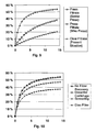
- Figure 9 illustrates separation efficiencies of lipophilic extractives (%) as a function of the filtrate volume discharged from the process (l/kg abs. dry pulp) obtained from a simulation according to Figure 6 with different process filtrates.
- a screw press reaches a level of its own. Its separation efficiency very quickly rises over thirty percent and ends up at over fifty percent. The separation efficiency of a wire press rises more slowly, however, reaching in the end a level of close to forty percent.
- Figure 10 illustrates separation efficiencies of lipophilic extractives (%) as a function of the filtrate volume flowing to the solids recovery (l/kg abs. dry pulp) obtained from a simulation according to Figure 6 with different solids recovery methods.
- the recovery methods were the same as in Figure 6 .
- the best separation efficiency was reached with a decanter centrifuge or, when solids were not recovered, the screening method was a little worse and the disc filter even a little worse than the screening method.
- Figure 11 illustrates consistencies (%) of the discharged pulp as a function of the filtrate volume flowing to the fibre recovery (l/kg abs. dry pulp) obtained from a simulation according to Figure 6 with different solids recovery methods.
- An interesting feature is that the consistency of the discharging pulp remains practically constant irrespective of the volume of filtrate with all other recovery methods except with the screening method with which the consistency decreased from forty percent to less than 25 percent.
- a process application according to a preferred embodiment of the invention is illustrated in Figure 12 .
- the application is a PGW plant (also GW and other processes based on grinding), into which the wood material 140 is brought in the form of logs, which are ground under high pressure.
- the fibre suspension produced as a result of the grinding 142 is transported to a so-called hot loop thickening 144 where filtrate is removed from the suspension.
- the suspension itself continues thickened to a sorting 146 and the filtrate to a hot water tank 148.
- a part of the liquid from the hot water tank 148 is returned to the grinding 142 and a part is taken to a decanter centrifuge 60 where the solids S are recovered from the liquid in the manner described above and can be recycled to the process.
- the extractives E remaining in the liquid phase are discharged from the process separate from the solids S.
- FIG 13 illustrates a process application according to another preferred embodiment of the invention. Also this application relates to a PGW plant (also GW and other processes based on grinding) and resembles closely the application in Figure 12 ; in the version of Figure 13 , only a press 150 has been added after the hot loop thickener 144.
- the filtrate from the press 150 is taken to a filtrate tank 152 from which at least a portion of the filtrate is further taken to decanter centrifuge 60 where the extractive material and the solids to be recovered and to be recycled to the process are separated to form separate flows.
- Figure 14 illustrates a process application according to a third preferred embodiment of the invention.
- This application relates to a pulp manufacturing process portion following a sorting 160. After the sorting 160 the pulp suspension is guided to a thickening 162 where the filtrate is separated and transported to a circulation water tank 164. A portion of the filtrate is returned to the pulp suspension prior to the sorting 160 to dilute the suspension and a portion is guided to the decanter centrifuge 60 where the usable solid material S is separated from the filtrate for recycling to the process, and the extractive material E for removal from the process.
- FIG. 15 illustrates a process application according to a fourth preferred embodiment of the invention.
- This application relates to a thickening and pressing process preceding the bleaching of mechanical or chemi-mechanical pulp.
- a thickening 170 in which filtrate is removed to a circulation water tank 172 in order to raise the consistency.
- the thickened fibre suspension is introduced further to a bleaching press 174, where filtrate is further removed from the suspension.
- the fibre suspension travels from the bleaching press 174 to bleaching 176 and the filtrate from the press 174 to a filtrate tank 178.
- a portion of the filtrate collected to the filtrate tank 178 is transported to dilute the pulp before the thickening 170 and a portion to the decanter centrifuge 60, where the filtrate is divided in the way described above into a fraction containing solids S to be recycled into the process, and into a fraction containing extractives E to be removed from the process.
- FIG 16 illustrates a process application according to a fifth preferred embodiment of the invention suitable for use in connection with any of the processes covered by this invention.
- the decanter centrifuge has been arranged to treat filtrate from a washing press 182 following a bleaching180.
- a portion of the filtrate of the washing press 182 is guided from the filtrate tank 184 back to the process to be used prior to the press 182 in the dilution of the fibre suspension while a portion flows to the decanter centrifuge 60.
- the solid material S is separated from the filtrate for recycling to the process and the extractives E for removal from the process.
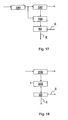
- FIG 17 illustrates a process application according to a sixth preferred embodiment of the invention. It describes a refining process (CTMP or APMP); the fibre suspension obtained after a refining phase 190 of the process is transported to a press 192 in which filtrate is pressed out from the suspension by a known method. The filtrate is guided to a filtrate tank 194 from which at least a portion of the filtrate is guided to a decanter centrifuge 60, which separates from the filtrate the recoverable solids S to a flow of its own to be returned to the process and the extractive material E to a flow to be discharged from the process.
- CTMP refining process
- APMP APMP
- FIG 18 illustrates a process application according to a seventh preferred embodiment of the invention. Also that describes for example a refining process (TMP, CTMP, CMP, APMP and other processes in which the wood raw material is chopped into chips prior to at least a partial mechanical defiberizing), in which a first press 200 is arranged to treat the chips. It has been found advantageous to recover already at this stage at least part of the filtrate via a filtrate tank 202 to the decanter centrifuge 60 in order to separate from each other the extractives E, and the solids S to be returned to the process.
- TMP refining process
- CTMP CMP
- APMP partial mechanical defiberizing
- Figure 19 illustrates a process application according to an eighth preferred embodiment of the invention, suitable for use in connection with any mechanical or chemi-mechanical process.
- the figure illustrates how an apparatus 212 has been disposed after a filtrate tank 210 and prior to a decanter centrifuge 60; the apparatus 212 can be for example a screen, a separator, a fractionator, a thickener or a corresponding device, which is intended to have an appropriate influence on the filtrate to be introduced into the decanter centrifuge 60.
- One possibility is for example a thickener with which water is separated from the filtrate flowing to the decanter centrifuge whereby the size of the centrifuge required can be reduced as the liquid flow to be treated decreases.
- the process described also creates a situation where, when the apparatus 212 is for example a disc filter (the consistency of the incoming pulp for example 0.3%) whereby the extractives readily remain in the suspension thickened by the disc filter, there are in the filtrate of the disc filter (consistency 0 %) relatively small amounts of extractives as they accumulate into the cake (consistency 0,6 %) of the disc filter which is transported further to the centrifuge. Then, although the centrifuge can be fairly small in size the liquid flow it treats contains remarkable amounts of extractives.
- Another alternative is an apparatus separating fibre fractions with which a portion of the fibre can be removed before the centrifuge.
- the processed described above can include also washers, which in this context are devices in which the consistency of the pulp fed into the device and that of the pulp discharged from the devices are essentially the same.
- the filtrate of the washer is analogous with the filtrate of a thickener or a press or a corresponding device, which removes liquid from the pulp, and thus it can be treated in a decanter centrifuge or a corresponding device for separating extractives from the usable solids.
- the decanter centrifuge or the corresponding device 60 is always preceded by a filtrate stank, in suitable conditions this can be omitted altogether, in which case there is a pipeline extending from a press or a corresponding device to the decanted centrifuge or a corresponding device.
- the filtrate tank can be replaced by two or even three filtrate tanks if the preceding liquid removing devices allows separating several types of filtrates (for example cloudy, clear, super clear).
- each portion of the above filtrates can be used in the way desired (for example as dilution liquid, as liquid to be treated in a decanter centrifuge, as waste water to be transferred to a channel, etc.)
Landscapes
- Paper (AREA)
- Treatment Of Liquids With Adsorbents In General (AREA)
- Solid-Sorbent Or Filter-Aiding Compositions (AREA)
- Extraction Or Liquid Replacement (AREA)
Abstract
Description
- The present invention relates to a method and apparatus for recovering fibre and fibre-based solids from filtrates containing both solids and lipophilic extractive agents, i.e. extractives of the mechanical or chemi-mechanical pulp industry.
- Lipophilic extractives, i.e. mainly resin from wood, cause various problems particularly in the production of pulp and paper from mechanical or chemi-mechanical pulp. The most common problems are fouling of wires and showers, and deposits at the paper machine. Lipophilic extractives and their deposits also decrease the strength and brightness properties of the paper and cause holes in the paper. Mechanical and chemi-mechanical pulp production processes mentioned are for example TMP (ThermoMechanical Pulping), CTMP (ChemiThermoMechanical Pulping), GW (GroundWood), PGW (Pressure GroundWood), APMP (Alkaline Peroxide Mechanical Pulping), CMP (ChemiMechanical Pulping) and other corresponding processes which at least partly are based on mechanical detachment of fibres.
- Many paper mills, which have tried to reduce the use of water, have faced the problems described above. Thus, it is clear that in the future the more stringent discharge limits and the reductions in the use of water will increase the problems caused by detrimental substances in the paper manufacture. Based on studies on the subject, accumulation of lipophilic extractives in the water circulations causes one of the biggest problems in view of the reduction of water consumption. On the other hand, the interest to use wood species with higher extractives concentrations, such as pine from first felling and aspen, has been increasing all the time which further increases the need to have more efficient extractives removal methods.
- In the processes used to date, the amount of extractives in the paper machine is limited by washing the pulp and using various chemicals. Both performed studies and practical experience have shown that the methods used to date are not sufficient to prevent extractives from accumulating in the circulations when water circulations are closing. This is due to the fact that the dispersion of the extractives into water is reduced when the water consumption is reduced and the extractive retention in the washers increases. Results obtained from both mill-scale measurement and various simulations indicate that the accumulation of extractives could be prevented in the future by the following methods:
- 1. by changing the water circulations of the pulp mill so that filtrates containing higher extractives contents can be removed from the process;
- 2. by replacing the present washing equipment with more efficient ones (for example screw presses);
- 3. by using various internal cleaning methods.
- Modifying the water circulations and the use of more efficient washing equipment means in practice increasing the loss of solids multifold compared with the present situation. Modifying the water circulations alone would increase the solids loss to be even 4-5 fold compared with the present. More efficient presses in the wash of lipophilic extractives would increase the solids loss even from this up to 3-6 fold. Further, more efficient presses separate from the pulp to the water fine solids, which would have a clearly improving influence on the optic properties in the paper to be produced. Thus, if the filtrate from this press was removed from the process, the optic properties of the pulp would deteriorate. Changing the water circulations and employing more efficient presses presuppose development of more efficient fibre recovering equipment and introducing them into use.
- In the following, a conventional prior art process, a PGW (Pressure Ground Wood) process,
Fig. 1 , is described as an example, in which the wood is introduced into the process as logs which are then ground at 2 at a high pressure to a fibre suspension. Because of the high pressure, the temperature of the fibre suspension is high, which is why the following element in the process, thethickening device 4, is called a hot loop thickener. In thethickener 4, the consistency of the fibre suspension is raised by removing from it filtrate, which is introduced into ahot water tank 6. Part of the filtrate in question is pumped from thehot water tank 6 to serve as shower water in refining while the rest flows into achannel 8 and further to the water cleaning system of the mill. - The fibre suspension thickened in the
hot loop thickener 4 is then introduced intosorting 10, however, before that the suspension is diluted, 12, with liquid obtained at least partly from the process itself. From thesorting 10 the fibre suspension continues to adisc filter 14, which again removes liquid/filtrate from the suspension. Filtrates of two types are obtained from thedisc filter 14 by conventional methods, i. e. a clear filtrate and a cloudy filtrate, each into itsown filtrate tank cloudy filtrate tank 16, and also some filtrate from theclear filtrate tank 18 while the rest of the clear filtrate flows into thechannel 8 and from there further to the water purification system of the mill. Liquid from thecloudy filtrate tank 16 is used in thedilution 12 preceding thesorting 10 as already mentioned. - From the
disc filter 14 the thickened fibre suspension flows to ableach press 20 with which the consistency of the suspension is raised to the level required by the bleaching process. Filtrate from thebleach press 20 is collected to a bleachpress filtrate tank 22 and from there in most cases all of it is used in thedilution 24 preceding thedisc filter 14. The thickened fibre suspension from thebleach press 20 flows to a bleaching 26 (peroxide bleaching in the figure), which is followed by awashing press 28, which aims at removing reaction products of the bleaching from the fibre suspension. After the washing press 28 the suspension travels to the paper mill while the filtrate from thewashing press 28 flows to a washingpress filtrate tank 30. The filtrate collected there is used with filtrate from thebleach press 20 in thedilution 24 preceding thedisc filter 14 and with fresh water in a dilution 32 preceding thewashing press 28. It should be noted from the above description that the several dilution and the following pressing and thickening stages mentioned above mean in practice washing the fibre suspension whereby extractives or other substances detached from the fibres during the process and intended to be removed, are washed from the suspension. - Table I presents extractive and solids contents of various filtrates in a prior art process (
Fig. 1 ) and Table II illustrates solids contents and extractives retentions of various filtrates from prior art pressesTable I. Pulp mill filtrate Extractives concentration, mg/l Solids contents, mg/l PGW hot loop 40-80 100 - 200 Disc filter cloudy filtrate 75-150 100 - 200 clear filtrate 50-120 50 - 150 super clear filtrate 40 - 100 <50 Filtrate from press 200 - 600 cf. Table II. Table II. Press Extractives retention, % Filtrate solids content, mg/l Roll press 20-50 200-1000 Wire press 10-40 350-1000 Multi-press * 1500 - 3000 Screw press ~ 0 2000 - 4000 * Extractives retention of the press in question is not known. Based on the operation of the apparatus it may be concluded that the retention is smaller than with a wire press. - Based on both practical experience and performed studies, solids in the filtrate are known to deteriorate the operation of evaporation and filtration used as internal purification. It is a known fact that in evaporation the solids of the filtrate decrease the consistency of the concentrate. In membrane filtering the fibres are know to break the membrane.
- In the present mechanical and chemi-mechanical pulp production, fibre recovery is usually not employed, or if it is, the fibre recovery is based on screening and filtering methods or flotation. Problems with these methods are for example: the low consistency of the recovered solids, the retention of lipophilic extractives into the solids to be recovered and/or the poor solids recovery degree. The problems in the separation are mostly due to the high fines content in the filtrate, the size of the lipophilic extractives is approx. 0.1 - 2 µm and the size of the fibre material >5 µm which means that the filtering must employ a small hole size. Thus, the result achievable with the present fibre recovery methods is a compromise between the volume of the recovered fibres and the extractives load recycled to the process. Table III presents results obtained with various fibre recovery apparatus.
Table III. Method Solids recovery degree % Extractives returned % Discharge consistency % Operation principle of separation method Disc thickener 90-95 20-50 10-20 filtering through pulp cake Flotation 85-98 30-55 1 - 15 20 - 80 µm air bubble Micro screen 30-60 10-15 <1 screen plate with hole size 20-150 µm Certus microfilter ~100 93-99 * ceramic filter with hole size 1 µm Decanter centrifuge >85 ~0 25-30 settling based on centrifugal force *discharge consistency not given - The most common fibre recovering apparatus are disc and drum thickeners in which the fibre and the fines are filtered through a solids cake as completely as possible. This method gives a fairly high solids recovery degree but at the same time the solids cake filters efficiently also colloidal substances off from the water. If the thickness of the solids cake is decreased the retention of colloids decreases but also the solids recovery efficiency decreases.
- In screening methods, for example Microscreen and curved screen, where the flow or a doctor wipes the screen surface preventing the formation of a solids cake, the retention of colloidal material into the fibre material to be recovered is smaller or there is no retention, but also the solids recovery is poor. Screening methods are mostly used to remove long fibres. Also the final consistency of the recovered solids remains low and therefore the recovered solids cannot be recycled to the high consistency pulp without adversely influencing its consistency. If the recovered solids must be recycled to the feed pulp of the press or the filtrate tank, the fines fraction of the solids starts to concentrate in the circulation and impair the operation of the press itself. If the speed of the flow or the movement of the doctor is slowed down, a solids cake begins to form, which increases the retention of colloidal material.
- The flotation method gives a high degree of solids recovery. In a flotator air bubbles remove also colloidal material with the solids. A drawback of a flotator is the low consistency of the recovered material and the large share of the colloidal detrimental material returning to the process.
-
US-A- 5,468,396 discusses the treating of the process liquids of pulp and paper industry by means of a conventional centrifuge to remove from the liquids contaminants less dense than water, like resins. The document teaches how the filtrates of kraft pulping, for instance, are divided into three fractions in an ordinary centrifuge, the fractions being the light contaminants, purified liquid, and heavier contaminants, like fibers and fines. The specification teaches further that it would be advantageous to reduce the amount of fibers and fines in the liquid entering the centrifuge by means of a filter upstream of the centrifuge. And finally the specification teaches how the heavier contaminants are discharged from the apparatus intermittently via valves, which are opened for a short period. Thus, the apparatus of the US document is not purposed to continuous recovery of fibers from filtrates but rather to remove contaminants less dense than water from the, preferably, prefiltered filtrate. - The drawbacks of the prior art methods described above may be avoided by using in the solids recovery the centrifuge method and apparatus according to the invention according to which the solid material is removed mechanically. By selecting a suitable centrifugal force a situation is created where colloids containing lipophilic extractives do not settle but fibre and fibre-based solids do settle due to a higher density. In this way the solid material can be separated clean without lipophilic extractives attached to it.
- According to a first aspect of the present invention, there is provided a method of continuously recovering both fibre and fibre-based solids from a filtrate, said filtrate of the mechanical or chemi-mechanical wood pulp processing industry containing both solids and colloidal lipophilic extractive material, the method comprising the steps of a. transporting said filtrate to a centrifuge developing a strong central acceleration, said centrifuge being either a decanter centrifuge or a screen bowl centrifuge; b. in said centrifuge separating the filtrate into two fractions, namely a liquid fraction containing the colloidal lipophilic extractives and a further fraction containing said fibre and fibre-based solids, the strong central acceleration generated in said centrifuge being such that, said further fraction containing said fibre and fibre-based solids settles onto an inner surface of said centrifuge; c. mechanically discharging said separated further fraction containing fibre and fibre-based solids from said centrifuge with the help of a screw conveyor arranged within said centrifuge; and d. removing the liquid fraction from said centrifuge as a separate flow.
- According to a second aspect of the present invention, there is provided an apparatus for use in the mechanical and chemi-mechanical wood pulp processing industry, said apparatus comprising a device for separating a filtrate from mechanical or chemi-mechanical pulp, the filtrate containing both solids and colloidal lipophilic extractives, and a centrifuge for continuously recovering said fibre and fibre-based solids from the filtrate, wherein the centrifuge is either a decanter centrifuge or a screen bowl centrifuge, said centrifuge separating the filtrate into two fractions, namely a liquid fraction containing the colloidal lipophilic extractives and a further fraction containing said fibre and fibre-based solids, by generating a strong central acceleration in such a way that said further fraction containing said fibre and fibre-based solids settles onto an inner surface of said centrifuge, and wherein said further fraction containing said fibre and fibre-based solids is mechanically discharged from said centrifuge with the help of a screw conveyor arranged within said centrifuge and said liquid fraction is removed from said centrifuge as a separate flow.
- By using the method and apparatus of the invention, both a high consistency of the recovered solids and a high degree of recovery of fibres without the retention of lipophilic extractives are achieved. Thus there is no need to accept the aforementioned compromises. With the method and apparatus of the present invention, the consumption of water in paper mills can be more easily reduced than with prior art methods, and wood species having a higher content of extractives can be used in mechanical and chemi-mechanical pulp production.
- Other characteristic features of the method and apparatus of the invention for recovering fibre-based solids and separating lipophilic extractives are disclosed in the dependent claims.
- To enable a better understanding of the present invention, and to show how the same may be carried into effect, reference will now be made, by way of example only, to the accompanying drawings, in which:-
-
Fig. 1 illustrates a prior art process of manufacturing mechanical pulp ; -
Figs. 2a and 2b illustrate schematically the operation principle of two different centrifuges; -
Fig. 3 illustrates a so-called decanter centrifuge; -
Fig. 4 illustrates a so-called screen bowl centrifuge; -
Fig. 5 illustrates the results of a mill-scale test run of the method of the invention; -
Fig. 6 illustrates a flow sheet used in the simulation of the method of the invention; -
Fig. 7 illustrates the solids losses of the process obtained from the simulation according toFig. 6 with different solids recovering methods, as a function of the volume of the filtrate taken to the solids recovery; -
Fig. 8 illustrates the solids losses of the process obtained from the simulation according toFig. 6 with various process filtrates, as a function of the volume of the filtrate discharged from the process; -
Fig. 9 illustrates the separation efficiencies of lipophilic extractives obtained from the simulation according toFig. 6 with various process filtrates, as a function of the volume of the filtrate discharged from the process; -
Fig. 10 illustrates the separation efficiencies of lipophilic extractives obtained from the simulation according toFig. 6 with various solids recovery methods, as a function of the volume of the filtrate taken to the solids recovery; -
Fig. 11 illustrates the consistencies of the discharged pulp obtained from the simulation according toFig. 6 with various solids recovery methods, as a function of the volume of the filtrate taken to the solids recovery; -
Fig. 12 illustrates a preferred process application of the method and the apparatus of the invention; -
Fig. 13 illustrates another preferred process application of the method and the apparatus of the invention; -
Fig. 14 illustrates a third preferred process application of the method and the apparatus of the invention; -
Fig. 15 illustrates a fourth preferred process application of the method and the apparatus of the invention; -
Fig. 16 illustrates a fifth preferred process application of the method and the apparatus of the invention; -
Fig. 17 illustrates a sixth preferred process application of the method and the apparatus of the invention; -
Fig. 18 illustrates a seventh preferred process application of the method and the apparatus of the invention; and -
Fig. 19 illustrates an eighth preferred process application of the method and the apparatus of the invention. - At first the separation method used in the method of the invention and the apparatus used in connection with it are described in more detail. Centrifuging means a sorting or a separation process based on the centrifugal force. The centrifugal force created in the centrifuging has the same kind of an effect on material as the gravitational force in settling. However, the centrifugal force created in the centrifuging is hundreds or thousands of times stronger than the gravitational force; therefore centrifuging
- gives a higher speed of settling of the particles,
- produces a denser layer of solids, and
- separates smaller particles than settling.
- Centrifuges are divided into sedimentation and filtering centrifuges and into combinations of these. The sedimentation centrifuges mean apparatus in which the separation takes place by means of the centrifugal force, only (
Fig. 2a ). Apparatus of this kind are for example disc and decanter centrifuges, and tube and bottle centrifuges used in laboratories.Fig. 2a is a schematic illustration of a centrifuge which is composed of acylinder 40 to be rotated at a high speed and having a closed wall. The centrifugal force separates from the material supplied into thecylinder 40 the heavy fraction against the wall of the cylinder to adense layer 42 while the liquid and the lighter material remain aslayers 44 of their own on top of the solid material layer. - Filtering centrifuges in turn are, in a way, combinations of filtering devices and centrifuges (
Fig. 2b ). In filtering centrifuges the separation of particles itself takes place by filtering. The starting point of the filtering centrifuges as well is arotating cylinder 50, but unlike a sedimentation centrifuge, it has a porous surface provided with holes, slots or other apertures suitable for the purpose. The driving force in the filtering is, however, the hydrostatic pressure created by the centrifugal force, which is why the methods are classified in separation methods based on centrifuging. Like inFig. 2a , also in this embodiment the heavy material is accumulated onto the surface, in this case the perforated surface, of the cylinder and the lighter material closer to the axis of the cylinder. In this case, however, the liquid is removed via the apertures in thecylinder 50 and the extractives retain into the solid material layer. In the combinations of sedimentation and filtering centrifuges, particles are separated by means of the centrifugal force as in the sedimentation centrifuging. The combination apparatus additionally comprise a washing/thickening zone which functions according to the same principle as a filtering centrifuge. - Among other things the following properties are required from the centrifuge method used in the recovery of fibre and in the separation of fibre and extractives. The method must be continuous as the processes of the industry in this field are continuous and the liquid volumes to be treated are large. Batchtype operation is out of the question. The capacity must be high, at least ten litres per second. The method must be applicable in the treatment of sludges and suspensions. Also long-fibre suspensions are treated which further raises the requirements set on the apparatus. The fibre recovery degree must be high as the fibre is valuable paper manufacture raw material, which cannot be wasted. Naturally, significant extractives retention is not acceptable, either, as expressly a solution is sought by means of which the problems caused by extractives could be avoided in the manufacture of both pulp and paper. Further, the apparatus should be able to reach a high final consistency so as not to have to recycle the fibre returned from the apparatus for reuse back to the process via a thickener.
- Experience with a filtering centrifuge indicates that filtering centrifuges have the same kind of problems as the present screening and filtering methods. In other words, compromises have to be made between the extractives retention and the degree of fibre recovery. Continuous sedimentation centrifuges, from which the solid material is removed through nozzles or slots (these devices are know by commercial names nozzle bowl, solid-ejecting bowl and nozzle-valve bowl centrifuges) do not work, either, in the fibre recovery or the separation of extractives because of the risk of clogging on the solids side. Naturally, the danger of clogging can be reduced by diluting the fibre fraction but this results in a much too low discharge consistency.
- Based both on literature and practical experience the only possible apparatus for the applications in question would today be decanter centrifuges (
Fig. 3 ) and the so-called screen bowl centrifuges (Fig. 4 ) (a combination apparatus). The advantage provided by the separation methods applied in these devices is that they are capable of separating solids of very different lengths(5-5000, um) and using them, the solids can be removed at a high consistency. - The
decanter centrifuge 60 illustrated inFig. 3 and discussed for example in patent publicationEP-A1-447742 outer casing 62, which surrounds the rotating parts of the device and comprisesdischarge outlets rotating bowl 68, oneend 70 of which is in this structure conical and theother end 72 cylindrical. Each end of the bowl has been provided withdischarge openings end 72 of thebowl 68 having a larger diameter in theend plate 78 of thebowl 68, and at thenarrower end 70 directly along the periphery of the casing of thebowl 68. Thebowl 68 has been supported withbearings 80 at both the ends. Ascrew conveyor 82 has been placed inside thebowl 68, the screw thread of which extends close to the inner wall of thebowl 68. Thescrew conveyor 82 and thebowl 68 have been connected to each other viagears 86 so that a small difference is created between the rotation speed of thescrew conveyor 82 and that of thebowl 68. The purpose of this difference is to force thescrew conveyor 82 to feed the solids separated by the centrifugal force onto the inner surface of thebowl 68 towards theoutlet 74 at thenarrower end 70 of thebowl 68. Further, in the embodiment of the figure, there is apipe 88 extending from thenarrower end 70 of thebowl 68 into the hollow inner space of thescrew conveyor 82 and at the same time of thebowl 68; via this pipe the liquid to be treated is introduced into thescrew conveyor 82. There is one or areseveral holes 92 in thecasing 90 of thescrew conveyor 82 approximately at the bending point between theconical portion 70 and thecylindrical portion 72 of thebowl 68, or a little towards the end on theconical portion side 70 from the bending point. - The decanter centrifuge illustrated in the figure works so that the suspension to be treated is supplied via the
pipe 88 to thescrew conveyor 82, which rotates at a high speed. From there the liquid shoots out due to the centrifugal force created by the high rotational speed viaholes 92 into thebowl 68 and there, further due to the centrifugal force, the heavy solids are separated from the liquid onto the surface of thebowl 68 while the liquid, being lighter, remains further inside. Thescrew conveyor 82 rotating inside thebowl 68 scrapes with it solid material from the surface of thebowl 68 towards thenarrower end 70 of the bowl and from there towards theoutlet 74 while the liquid flows to the opposite direction, in other words to a direction where the liquid gets further away from the center line of therotating bowl 68. The thickness of the liquid layer in thebowl 68 is determined by theliquid outlets 76, or rather their distance from the inner surface of thebowl 68. Thus, the liquid is discharged from the bowl via the opposite end compared with the solids. Of course, also other clearly lighter solid material, such as in the case of the invention the extractive material particles, are removed with the liquid. In this way the separated fractions are discharged from the apparatus each via theirown outlets - Decanter centrifuges have been disclosed also in Swedish patent publications
509400 501213 Fig. 3 . Only for example the feed point of the liquid to be treated may vary which results in a little different flow directions of the fractions in the apparatus. - In a series of tests we performed it was found that the consistency of the solids accumulated on the surface of the centrifuge bowl 68 (i.e. in the layer between the liquid layer and the surface of the bowl) varied depending on the situation (among other things on the fibre-containing material and its volume) from a few percents even up to the level of about ten percent, sometimes even a little more than that. However, after the fibre layer had been scraped off by the
screw conveyor 82 towards the narrower end of the bowl by "lifting" the solids layer from the liquid, the consistency rose in most cases to exceed twenty percent, in some cases even up to more than thirty percent. - The screen bowl centrifuge illustrated in
Fig. 4 and disclosed inUS patent no. 5,321,898 works in principle in the same way. In other words the division of the liquid into fractions is performed with a uniform, non-perforated rotating surface. The only more significant difference is that in theseparation portion 96, into which in practise flows only solids separated from the liquid, there is ascreen surface 97 through which the finer fraction of the solids is removed from the apparatus to adischarge hopper 98. The coarser fraction of the solids is discharged via the end of the apparatus to adischarge chute 99. This portion may also be called a solids washing portion. - Thus, the solving of the problems the invention addresses can be started with an apparatus, the characteristic features of which are both that the liquid is divided into fractions by a revolving unbroken surface, and that the revolving speed of the apparatus, more precisely that of the bowl or the cylinder of the apparatus, is high. As in fact a more important factor than the revolving speed is the central acceleration the apparatus develops, we have determined it in our experiments. Based on the tests we have performed, the central acceleration should be more than 200 * g, preferably more than 700 * g, most preferably more than 1000 * g.
- In the following, a mill-scale test run is described, in which the function of a decanter centrifuge was tested in the separation of extractive material. A test run was performed with a solids recovery method and a method for separating solids and extractives in a productions scale PGW pulp production plant in connection with a paper mill. The wood species were spruce and the filtrate was filtrate from a washing press. The bleaching process was ditionite bleaching and the pulp was brought to the washing press directly from a disc filter. A bleaching press was not in use. The solids recovery apparatus was a decanter centrifuge; the capacity of the decanter centrifuge was informed by the producer of the apparatus to be 20 m3/h. The length of the centrifuge was 3975 mm, the width 1140 mm and the height 1570 mm.
Figure 5 illustrates the different degrees of solids recovery at different feed rates as a function of the rotating speed of the decanted cylinder. - From the test results it is worth mentioning that, as is clear also in theory, the separation efficiency of the centrifuge increased when the number of revolutions was raised. An increase in the revolution speed from 2260 rpm to 2640 rpm at a capacity of 20 m3/h raised the recovery degree from 82 % to 88 %. It should also be noted that at the maximum capacity the recovery degree at 2640 rpm was still of the order of 82 %.
- The test apparatus was adjusted to give as high a discharge consistency of the solids as possible. This kind of an adjustment is as such better suited in the concentration of the biological sludge of waste water treatment plants than in the treatment of pulp production waters. By optimising the apparatus the solids recovery degree and the capacity can be improved further.
- The application of the method of the invention in a conventional mechanical pulp production process is described in the following (
Fig. 6 ). In the figure, thereference number 100 refers to the wood material brought to the process, the material being diluted to a suitable consistency at 102. Filtrate from thecirculation water tank 104 of the process is used in the dilution. The pulp obtained from the dilution is brought toscreening 106 and the accepted fraction obtained from the screening is thickened for example with adisc filter 108. The purpose of the thickening is both, as is natural, to raise the consistency of the pulp and to remove extractives from the pulp. The thickened pulp is reintroduced todilution 110 where the consistency is adjusted to be suitable for further processing. Subsequently, the pulp is brought to awasher 112, which is preferably a press, either a screw or a wire press. After the wash thepulp 114 is transported either directly to the paper mill or to bleaching. -
Figure 6 illustrates also, how the filtrate from thethickener 108, which in this example is disc filter, and the wash filtrate from thewasher 112, however, via afiltrate tank 116 of its own, are brought to acirculation water tank 104, where filtrates from different sources are mixed with each other. - Up to this point only a prior art method of mechanical pulp production has been described. Now, in order to test the method of the invention, a
decanter centrifuge 60 has been connected to the process and filtrate obtained from thewasher 112 is brought from thefiltrate tank 116 to the decanter centrifuge via avalve 118. The task of thecentrifuge 60 is to recover from the filtrate fibre material suitable for paper production, the material being guided in aflow 120 topulp 114, which is forwarded to further processing, and to separate from the filtrate lipophilic extractives to aseparate flow 122. -
Figure 6 further illustrates with thereference number 124 clean fresh water brought to the process to replace the water volume discharged from the process. Water is removed for example with thepulp 114 discharged from the process and both from thecirculation water tank 104 in theflow 126 and from thefiltrate tank 116 with the extractives in theflow 122. - In the study of the process described above, a simulation model was used with which results were obtained which correspond very well to the reality. The simulation was carried out with the version 2.4.08 of the Balas simulation program. The flow sheet presented in
Figure 6 has been drawn with the version 4.45 of the FloSheet program delivered with the Balas simulation program. In the simulation model the arrows indicate the direction of the flow in question. The following mathematical methods and parameters have been used in the simulation model: - The simulations takes place in a balanced situation when the operation of the process is stable.
- In the simulation, a 'softwood' component is treated as the solid material, lipophilic extractive material both in a water phase and in a solids phase as the 'org' component, and water as the 'water' component.
- The consistency has been determined by dividing the 'softwood' flow by the total flow, in other words the lipophilic extractives have not been calculated as solids.
- Lipophilic extractives only in the water phase can be separated with the water in a press/thickener, the lipophilic extractives in the solid phase move with the solid material. Thus, the retention of the lipophilic extractives relates to the behaviour of lipophilic extractives in the water phase, only.
- The retained lipophilic extractives remain in the water phase.
- The flows and apparatus of the simulation model:
100 Wood into the process. The solids flow is chosen to be 1 kg/s. The total volume of lipophilic extractives is known to be 8 mg/g and their share in the water phase is 60 %. The water flow is 0.992 kg/s. Thus, the consistency is 50 % and the total flow rate 2 kg/s.102 Dilution to a consistency of 0.65 % for screening 106 (not used in the simulation). The dilution is performed with filtrate from the circulation water tank 7. The module used is CONSIS. 108 Thickening, the typical values of the disc filter are used in the simulation. The final consistency 13 %, the retention of lipophilic extractives 30 %, thesolids recovery degree 99 %, the calculation module used FLOTA2. Because of its simplicity, this thickener, which corresponds to a disc, produces only one filtrate. The solids content of the filtrate is 68.4 mg/l.110 Dilution with the filtrate from the circulation water tank 44 to a consistency of 6 %. The module used CONSIS.112 A press serving as a washer. In the simulation, typical readings of both a wire press and a screw press have been used for comparison. - the values of a wire press: final consistency 40 %, retention oflipophilic extractives 30 %, recovery degree ofsolids 99 %, the module used FLOTA2. The solids content of the filtrate of this press is 704,6 mg/l.- the values of a screw press: final consistency 40 %, retention oflipophilic extractives 0 %, recovery degree ofsolids 97 %, the module used FLOTA2. The solids content of the filtrate of this press is 2106,5 mg/l.114 The pulp discharged from the process directly to the paper mill or to bleaching. Also the solids 120 obtained from the solids recovery is introduced into this pulp.104 A circulation water tank where the incoming waters are completely mixed with each other. The module used MIXDIV. 116 The filtrate tank of the press. The module used MIXDIV. 60 Recovery of solids. The decanter centrifuge parameters measured earlier or otherwise known, and typical parameters of a disc filter and a screening method were used. In some simulations, solids were not recovered, in these cases the filtrate was guided unchanged past the solids recovery to the discharging filtrate 122 of thepress 112. - The values of the decanter centrifuge: final consistency 27 %, retention oflipophilic extractives 0 %, recovery degree ofsolids 90 %, the module used FLOTA2. - The values of the screening method: final consistency 1%, retention oflipophilic extractives 0 %, recovery degree ofsolids 60 %, the module used FLOTA2. - The values of the disc filter:final consistency 15 %, retention oflipophilic extractives 30 %, recovery degree of solids 95 %, the module used FLOTA2.124 Fresh water to be fed into the process, which replaces the water discharged. Water is discharged for the process with the discharged pulp 114 and in thecirculation water discharge 126 and filtrate discharged, 122, of thepress 116 if they are used. This replacing fresh water is perfectly clean water.122 Water fraction from the solids recovery, which is discharged from the process. 126 Water fraction from the circulation water tank 104, which is discharged from the process.118 Valve for regulating the solilds flow to the solids recovery. The module used FSET. 128 Valve for regulating the water fraction 126 discharged from the process from thecirculation water tank 104. The module used FSET. -
Figure 7 illustrates the solids losses (%) of the process obtained from a simulation according toFigure 6 as a function of the filtrate volume flowing to the solids recovery(l/kg abs. dry matter) with different solids recovery methods. The recovery methods were a decanter centrifuge, a screening method and a disc filter. For comparison, also a case was taken up where solids were not recovered. The results indicate that the solids losses with a decanter centrifuge and a disc filter are essentially the same, i. e. less than 10 % compared with a situation where solids were not recovered. In the screening method on the other hand, the solids losses were a little more than one third compared with the situation with no fibre recovery. -
Figure 8 illustrates solids losses (%) of the process obtained from a simulation according toFigure 6 as a function of the filtrate volume (l/kg abs. dry pulp) discharged from the process with different process filtrates. The process filtrates treated were filtrates from a screw press and a wire press and for comparison so-called clear filtrate of the present technology. The amount of solids removed with the filtrate from a screw press is about three times the amount removed by a wire press, and roughly expressed about twenty times the amount removed with a clear filtrate. -
Figure 9 illustrates separation efficiencies of lipophilic extractives (%) as a function of the filtrate volume discharged from the process (l/kg abs. dry pulp) obtained from a simulation according toFigure 6 with different process filtrates. In the separation of lipophilic extractives a screw press reaches a level of its own. Its separation efficiency very quickly rises over thirty percent and ends up at over fifty percent. The separation efficiency of a wire press rises more slowly, however, reaching in the end a level of close to forty percent. -
Figure 10 illustrates separation efficiencies of lipophilic extractives (%) as a function of the filtrate volume flowing to the solids recovery (l/kg abs. dry pulp) obtained from a simulation according toFigure 6 with different solids recovery methods. The recovery methods were the same as inFigure 6 . The best separation efficiency was reached with a decanter centrifuge or, when solids were not recovered, the screening method was a little worse and the disc filter even a little worse than the screening method. -
Figure 11 illustrates consistencies (%) of the discharged pulp as a function of the filtrate volume flowing to the fibre recovery (l/kg abs. dry pulp) obtained from a simulation according toFigure 6 with different solids recovery methods. An interesting feature is that the consistency of the discharging pulp remains practically constant irrespective of the volume of filtrate with all other recovery methods except with the screening method with which the consistency decreased from forty percent to less than 25 percent. - Thinking more broadly, the results clearly indicate that removing filtrate from the circulation water tank gives a remarkably weaker separation efficiency than separating filtrate from a wire press serving as the press. The separation efficiency can still be improved by replacing the wire press with a screw press, which does not retain lipophilic extractives. Improving the separation efficiency also strongly increases fibre losses. Solids losses of this magnitude are not acceptable.
- The use of a decanter centrifuge does not impair the separation efficiency whereas other recovery methods do (
Fig. 10 ). The use of a screening method brings about the additional problems of great solids losses (Fig. 7 ) and a decrease in the consistency of the discharged pulp (Fig. 11 ). The decrease in the consistency of the discharged pulp prevents the recycling of the recovered solids to the high-consistency pulp of the press at a point of the process where high consistency is important (for example the operation of a high consistency bleaching). - The results indicate that by using a decanter centrifuge in the recovery of solids and an efficient press (for example a screw press) the water consumption of the process can be reduced remarkably from the present situation. Despite the reduction of water consumption to one fifth, the separation effeciency of lipophilic extractives is almost doubled.
- A process application according to a preferred embodiment of the invention is illustrated in
Figure 12 . The application is a PGW plant (also GW and other processes based on grinding), into which thewood material 140 is brought in the form of logs, which are ground under high pressure. The fibre suspension produced as a result of the grinding 142 is transported to a so-called hot loop thickening 144 where filtrate is removed from the suspension. The suspension itself continues thickened to a sorting 146 and the filtrate to ahot water tank 148. A part of the liquid from thehot water tank 148 is returned to the grinding 142 and a part is taken to adecanter centrifuge 60 where the solids S are recovered from the liquid in the manner described above and can be recycled to the process. The extractives E remaining in the liquid phase are discharged from the process separate from the solids S. -
Figure 13 illustrates a process application according to another preferred embodiment of the invention. Also this application relates to a PGW plant (also GW and other processes based on grinding) and resembles closely the application inFigure 12 ; in the version ofFigure 13 , only apress 150 has been added after thehot loop thickener 144. In this embodiment the filtrate from thepress 150 is taken to afiltrate tank 152 from which at least a portion of the filtrate is further taken todecanter centrifuge 60 where the extractive material and the solids to be recovered and to be recycled to the process are separated to form separate flows. - The process applications illustrated in the following
Figures 14 - 16 are applicable in any mechanical or chemi-mechanical pulp production process.Figure 14 illustrates a process application according to a third preferred embodiment of the invention. This application relates to a pulp manufacturing process portion following a sorting 160. After the sorting 160 the pulp suspension is guided to a thickening 162 where the filtrate is separated and transported to acirculation water tank 164. A portion of the filtrate is returned to the pulp suspension prior to the sorting 160 to dilute the suspension and a portion is guided to thedecanter centrifuge 60 where the usable solid material S is separated from the filtrate for recycling to the process, and the extractive material E for removal from the process. -
Figure 15 illustrates a process application according to a fourth preferred embodiment of the invention. This application relates to a thickening and pressing process preceding the bleaching of mechanical or chemi-mechanical pulp. Before the bleaching itself the pulp is fed into a thickening 170, in which filtrate is removed to acirculation water tank 172 in order to raise the consistency. The thickened fibre suspension is introduced further to ableaching press 174, where filtrate is further removed from the suspension. The fibre suspension travels from thebleaching press 174 to bleaching 176 and the filtrate from thepress 174 to afiltrate tank 178. A portion of the filtrate collected to thefiltrate tank 178 is transported to dilute the pulp before the thickening 170 and a portion to thedecanter centrifuge 60, where the filtrate is divided in the way described above into a fraction containing solids S to be recycled into the process, and into a fraction containing extractives E to be removed from the process. -
Figure 16 illustrates a process application according to a fifth preferred embodiment of the invention suitable for use in connection with any of the processes covered by this invention. In this application the decanter centrifuge has been arranged to treat filtrate from awashing press 182 following a bleaching180. In the figure, a portion of the filtrate of thewashing press 182 is guided from thefiltrate tank 184 back to the process to be used prior to thepress 182 in the dilution of the fibre suspension while a portion flows to thedecanter centrifuge 60. In thedecanter centrifuge 60, the solid material S is separated from the filtrate for recycling to the process and the extractives E for removal from the process. -
Figure 17 illustrates a process application according to a sixth preferred embodiment of the invention. It describes a refining process (CTMP or APMP); the fibre suspension obtained after arefining phase 190 of the process is transported to apress 192 in which filtrate is pressed out from the suspension by a known method. The filtrate is guided to afiltrate tank 194 from which at least a portion of the filtrate is guided to adecanter centrifuge 60, which separates from the filtrate the recoverable solids S to a flow of its own to be returned to the process and the extractive material E to a flow to be discharged from the process. -
Figure 18 illustrates a process application according to a seventh preferred embodiment of the invention. Also that describes for example a refining process (TMP, CTMP, CMP, APMP and other processes in which the wood raw material is chopped into chips prior to at least a partial mechanical defiberizing), in which afirst press 200 is arranged to treat the chips. It has been found advantageous to recover already at this stage at least part of the filtrate via afiltrate tank 202 to thedecanter centrifuge 60 in order to separate from each other the extractives E, and the solids S to be returned to the process. -
Figure 19 illustrates a process application according to an eighth preferred embodiment of the invention, suitable for use in connection with any mechanical or chemi-mechanical process. The figure illustrates how anapparatus 212 has been disposed after afiltrate tank 210 and prior to adecanter centrifuge 60; theapparatus 212 can be for example a screen, a separator, a fractionator, a thickener or a corresponding device, which is intended to have an appropriate influence on the filtrate to be introduced into thedecanter centrifuge 60. One possibility is for example a thickener with which water is separated from the filtrate flowing to the decanter centrifuge whereby the size of the centrifuge required can be reduced as the liquid flow to be treated decreases. In addition to the rise in the consistency, the process described also creates a situation where, when theapparatus 212 is for example a disc filter (the consistency of the incoming pulp for example 0.3%) whereby the extractives readily remain in the suspension thickened by the disc filter, there are in the filtrate of the disc filter (consistency 0 %) relatively small amounts of extractives as they accumulate into the cake (consistency - It should also be noted that, as was already stated in connection with the prior art, the dilution and the subsequent thickening/pressing in fact corresponds to a washing of the pulp. Thus, it is clear that as far as this invention is concerned the processed described above can include also washers, which in this context are devices in which the consistency of the pulp fed into the device and that of the pulp discharged from the devices are essentially the same. Thus, it is also clear that the filtrate of the washer is analogous with the filtrate of a thickener or a press or a corresponding device, which removes liquid from the pulp, and thus it can be treated in a decanter centrifuge or a corresponding device for separating extractives from the usable solids.
- It should be noted from the above description, that although the whole description speaks about a decanter centrifuge the method may employ a screen bowl centrifuge as described above.
- Further, it should be understood that although in the example above the decanter centrifuge or the
corresponding device 60 is always preceded by a filtrate stank, in suitable conditions this can be omitted altogether, in which case there is a pipeline extending from a press or a corresponding device to the decanted centrifuge or a corresponding device. In the same way, the filtrate tank can be replaced by two or even three filtrate tanks if the preceding liquid removing devices allows separating several types of filtrates (for example cloudy, clear, super clear). Thus it is further clear that each portion of the above filtrates can be used in the way desired (for example as dilution liquid, as liquid to be treated in a decanter centrifuge, as waste water to be transferred to a channel, etc.) - As can be understood from the above description, a new type of a method has been developed for treating the filtrates of the mechanical and chemimechanical wood processing industry and in particular for removing lipophilic extractives from the filtrates in question. It should be kept in mind that the several examples of the invention described above are only illustrative examples of the many variations of the invention that is defined in the appended claims.
Claims (11)
- A method of continuously recovering both fibre and fibre-based solids from a filtrate of the mechanical or chemi-mechanical pulp wood processing industry, said filtrate containing both solids and colloidal lipophilic extractive material, the method comprising the steps ofa. transporting said filtrate to a centrifuge (60) developing a strong central acceleration, said centrifuge (60) being either a decanter centrifuge or a screen bowl centrifuge;b. in said centrifuge (60) separating the filtrate into two fractions, namely a liquid fraction (E) containing the colloidal lipophilic extractives and as further fraction (S) containing said fibre and fibre-based solids, the strong central acceleration generated in said centrifuge (60) being such that said further fraction containing said fibre and fibre-based solids settles onto an inner surface of said centrifuge (60) ;c. mechanically discharging said separated further fraction (s) containing fibre and fibre-based solids from said centrifuge (60) with the help of a screw conveyor (82) arranged within said centrifuge (60); andd. removing the liquid fraction (E) from said centrifuge (60) as a separate flow.
- A method according to claim 1, wherein said filtrate is the filtrates of a washer (112), a press or a thickener.
- A method according to claim 1, wherein said further fraction (S) containing the fibre and the fibre-based solids is discharged from said centrifuge (60) at a consistency of more than 20 percent so that it can be recycled straight to the main pulp flow of either a paper mill or a bleaching process.
- A method according to claim 3, wherein said filtrate is:- the filtrate from a hot loop thickening step (144) of a pulp producing plant, or- the filtrate from a press (150) following a hot loop thickening step (144) of a pulp producing plant, or- the filtrate from a thickening step (162) following a sorting step (160) in a pulp producing plant, or- the filtrate from a bleaching press (174) preceding a bleaching step (176) in a pulp producing plant, or- the filtrate from a washing press (182) following a bleaching step (180) in a pulp producing plant, or- the filtrate from a press (192) following a refining step (190) in a pulp producing plant, or- the filtrate from a chip press (200) in a pulp producing plant.
- A method according to claim 1, wherein prior to step a), said filtrate is treated at least in one of a fractionator, a thickener, a screen or a separator.
- A method according to claim 1, wherein the central acceleration is greater than 200*g.
- An apparatus for use in the mechanical and chemi-mechanical wood pulp processing industry, said apparatus comprising a device (112, 144, 150, 162, 174, 182, 192, 200) for separating a filtrate from mechanical or chemi-mechanical pulp, the filtrate containing both solids and colloidal lipophilic extractives, and a centrifuge (60) for continuously recovering said fibre and fibre-based solids from the filtrate, wherein the centrifuge (60) is either a decanter centrifuge or a screen, bowl centrifuge, said centrifuge (60) separating the filtrate into two fractions, namely a liquid fraction (E) containing the colloidal lipophilic extractives and a further fraction (S) containing said fibre and fibre-based solids, by generating a strong central acceleration in such a way that said further fraction (S) containing said fibre and fibre-based solids settles onto an inner surface of said centrifuge (60), and wherein said further fraction (S) containing said fibre and fibre-based solids is mechanically discharged from said centrifuge (60) with the help of a screw conveyor (82) arranged within said centrifuge (60) and said liquid fraction (E) is removed from said centrifuge (60) as a separate flow.
- An apparatus according to claim 7, wherein a device, (212) for pre-treating the filtrate is provided between said filtrate separating device and said centrifuges
- An apparatus according to claim 8, wherein the pre-treating device (212) is a screen, a thickener, a fractionator and/or a separator.
- An apparatus according to claim 7, wherein said inner surface of said centrifuge (60) on which said further material fraction (S) containing said fibre and fibre-based solids settles during separation is unbroken.
- An apparatus according to claim 10, wherein the filtrate separating device (112, 144, 150, 162, 174, 182, 192, 200) is a thickener, a press or a washer.
Applications Claiming Priority (3)
| Application Number | Priority Date | Filing Date | Title |
|---|---|---|---|
| FI20010967 | 2001-05-09 | ||
| FI20010967A FI110580B (en) | 2001-05-09 | 2001-05-09 | Process for the recovery of fiber and fiber-based solids and for the separation of lipophilic extractant |
| PCT/FI2002/000391 WO2002090647A1 (en) | 2001-05-09 | 2002-05-07 | Method and apparatus for recovering fibre and fibre-based solids from filtrates containing both solids and liposoluble extractive agents of mechanical or chemi-mechanical pulp industry |
Publications (2)
| Publication Number | Publication Date |
|---|---|
| EP1392913A1 EP1392913A1 (en) | 2004-03-03 |
| EP1392913B1 true EP1392913B1 (en) | 2009-07-01 |
Family
ID=8561155
Family Applications (1)
| Application Number | Title | Priority Date | Filing Date |
|---|---|---|---|
| EP02722318A Expired - Lifetime EP1392913B1 (en) | 2001-05-09 | 2002-05-07 | Method and apparatus for recovering fibre and fibre-based solids from a filtrate of the mechanical or chemi-mechanical wood pulp industry, said filtrate containing both solids and lipophilic extractive material |
Country Status (6)
| Country | Link |
|---|---|
| EP (1) | EP1392913B1 (en) |
| AT (1) | ATE435328T1 (en) |
| CA (1) | CA2446407C (en) |
| DE (1) | DE60232791D1 (en) |
| FI (1) | FI110580B (en) |
| WO (1) | WO2002090647A1 (en) |
Cited By (1)
| Publication number | Priority date | Publication date | Assignee | Title |
|---|---|---|---|---|
| WO2021253107A1 (en) * | 2020-06-17 | 2021-12-23 | Suzano S.A. | Method to treat a condensate in a pulping process |
Families Citing this family (1)
| Publication number | Priority date | Publication date | Assignee | Title |
|---|---|---|---|---|
| CN102392381B (en) * | 2011-08-02 | 2013-09-25 | 华南理工大学 | Chemi-mechanical pulp waste liquid alkaline recycling pretreatment method |
Family Cites Families (4)
| Publication number | Priority date | Publication date | Assignee | Title |
|---|---|---|---|---|
| DD223479A1 (en) * | 1984-04-12 | 1985-06-12 | Zellstoff U Papierfabrik Rosen | METHOD FOR THE MECHANICAL ENTRAINING OF SULPHITE-LIQUID |
| FI81396C (en) * | 1988-10-25 | 1990-10-10 | Enso Gutzeit Oy | FOERFARANDE FOER BEHANDLING AV AVFALLSVATTEN FRAON TRAEFOERAEDLINGSINDUSTRINS MASSAFRAMSTAELLNINGSPROCESSER. |
| US5321898A (en) * | 1992-06-19 | 1994-06-21 | Decanter Machine, Inc. | Centrifugal screen bowl dryer |
| US5468396A (en) * | 1994-03-16 | 1995-11-21 | Pulp And Paper Research Institute Of Canada | Centrifugal cleaning of pulp and paper process liquids |
-
2001
- 2001-05-09 FI FI20010967A patent/FI110580B/en not_active IP Right Cessation
-
2002
- 2002-05-07 WO PCT/FI2002/000391 patent/WO2002090647A1/en not_active Application Discontinuation
- 2002-05-07 DE DE60232791T patent/DE60232791D1/en not_active Expired - Lifetime
- 2002-05-07 CA CA002446407A patent/CA2446407C/en not_active Expired - Fee Related
- 2002-05-07 EP EP02722318A patent/EP1392913B1/en not_active Expired - Lifetime
- 2002-05-07 AT AT02722318T patent/ATE435328T1/en not_active IP Right Cessation
Cited By (1)
| Publication number | Priority date | Publication date | Assignee | Title |
|---|---|---|---|---|
| WO2021253107A1 (en) * | 2020-06-17 | 2021-12-23 | Suzano S.A. | Method to treat a condensate in a pulping process |
Also Published As
| Publication number | Publication date |
|---|---|
| CA2446407C (en) | 2010-01-12 |
| FI20010967A0 (en) | 2001-05-09 |
| WO2002090647A1 (en) | 2002-11-14 |
| FI110580B (en) | 2003-02-28 |
| CA2446407A1 (en) | 2002-11-14 |
| DE60232791D1 (en) | 2009-08-13 |
| ATE435328T1 (en) | 2009-07-15 |
| FI20010967A (en) | 2002-11-10 |
| EP1392913A1 (en) | 2004-03-03 |
Similar Documents
| Publication | Publication Date | Title |
|---|---|---|
| CA2133630C (en) | Method and apparatus for screening waste paper pulp | |
| KR900004943B1 (en) | A waste paper preparation system | |
| US8025772B2 (en) | Method for degassing and supplying a fibrous suspension to a headbox or a filter device and degassing device | |
| DE68928632T2 (en) | Process and apparatus for treating pulp | |
| FI82082B (en) | FOERFARANDE OCH ANORDNING FOER BEHANDLING AV MASSA. | |
| TW444077B (en) | Method and apparatus for screening waste paper pulp | |
| US8262849B2 (en) | Apparatus and method for manufacturing fibre mass suspension | |
| US5468396A (en) | Centrifugal cleaning of pulp and paper process liquids | |
| CA2085306C (en) | Method and apparatus for treating white water | |
| US2641164A (en) | Method for processing fibrous pulp | |
| EP1392913B1 (en) | Method and apparatus for recovering fibre and fibre-based solids from a filtrate of the mechanical or chemi-mechanical wood pulp industry, said filtrate containing both solids and lipophilic extractive material | |
| SE527041C2 (en) | Method for selectively removing marrow cells from cellulose pulp | |
| RU2218458C2 (en) | Method and apparatus for producing of paper pulp from waste paper | |
| JPS62199888A (en) | Method and apparatus for removing ink from fiber suspension obtained from old paper | |
| US5470432A (en) | Method and arrangement for the treatment of a fiber suspension | |
| CA2634529C (en) | Method for preparing paper pulp from recycled paper containing contaminants | |
| US7163604B2 (en) | Production of fiber suspension from waste paper | |
| CN105637144B (en) | A method of and an arrangement for introducing process liquid from a treatment step to a washing and/or filtering apparatus | |
| JPS5934834B2 (en) | Method and apparatus for recovering paper fibers from raw materials including waste paper | |
| CN109983175B (en) | Apparatus for treatment of process water | |
| AU750899B2 (en) | Screening of fibrous suspensions | |
| FI113948B (en) | Procedures and devices for treating backwater | |
| Holik et al. | Stock preparation | |
| WO2004067838A1 (en) | Method and device for handling filler-containing broke in a paper machine and a board machine | |
| WO1994025667A1 (en) | Apparatus and method for treating a pulp slurry of waste paper |
Legal Events
| Date | Code | Title | Description |
|---|---|---|---|
| PUAI | Public reference made under article 153(3) epc to a published international application that has entered the european phase |
Free format text: ORIGINAL CODE: 0009012 |
|
| 17P | Request for examination filed |
Effective date: 20031205 |
|
| AK | Designated contracting states |
Kind code of ref document: A1 Designated state(s): AT BE CH CY DE DK ES FI FR GB GR IE IT LI LU MC NL PT SE TR |
|
| AX | Request for extension of the european patent |
Extension state: AL LT LV MK RO SI |
|
| RAP1 | Party data changed (applicant data changed or rights of an application transferred) |
Owner name: V & K CONSULTING OY |
|
| GRAP | Despatch of communication of intention to grant a patent |
Free format text: ORIGINAL CODE: EPIDOSNIGR1 |
|
| RTI1 | Title (correction) |
Free format text: METHOD AND APPARATUS FOR RECOVERING FIBRE AND FIBRE-BASED SOLIDS FROM A FILTRATE OF THE MECHANICAL OR CHEMI-MECHANICAL WOOD PULP INDUSTRY, SAID FILTRATE CONTAINING BOTH SOLIDS AN |
|
| RIC1 | Information provided on ipc code assigned before grant |
Ipc: D21F 1/66 20060101ALI20081204BHEP Ipc: D21C 5/00 20060101AFI20081204BHEP |
|
| GRAS | Grant fee paid |
Free format text: ORIGINAL CODE: EPIDOSNIGR3 |
|
| GRAA | (expected) grant |
Free format text: ORIGINAL CODE: 0009210 |
|
| RAP1 | Party data changed (applicant data changed or rights of an application transferred) |
Owner name: ANDRITZ AG |
|
| AK | Designated contracting states |
Kind code of ref document: B1 Designated state(s): AT BE CH CY DE DK ES FI FR GB GR IE IT LI LU MC NL PT SE TR |
|
| REG | Reference to a national code |
Ref country code: GB Ref legal event code: FG4D |
|
| REG | Reference to a national code |
Ref country code: CH Ref legal event code: EP |
|
| REG | Reference to a national code |
Ref country code: IE Ref legal event code: FG4D |
|
| REF | Corresponds to: |
Ref document number: 60232791 Country of ref document: DE Date of ref document: 20090813 Kind code of ref document: P |
|
| REG | Reference to a national code |
Ref country code: SE Ref legal event code: TRGR |
|
| NLV1 | Nl: lapsed or annulled due to failure to fulfill the requirements of art. 29p and 29m of the patents act | ||
| PG25 | Lapsed in a contracting state [announced via postgrant information from national office to epo] |
Ref country code: FI Free format text: LAPSE BECAUSE OF FAILURE TO SUBMIT A TRANSLATION OF THE DESCRIPTION OR TO PAY THE FEE WITHIN THE PRESCRIBED TIME-LIMIT Effective date: 20090701 Ref country code: ES Free format text: LAPSE BECAUSE OF FAILURE TO SUBMIT A TRANSLATION OF THE DESCRIPTION OR TO PAY THE FEE WITHIN THE PRESCRIBED TIME-LIMIT Effective date: 20091012 |
|
| PG25 | Lapsed in a contracting state [announced via postgrant information from national office to epo] |
Ref country code: NL Free format text: LAPSE BECAUSE OF FAILURE TO SUBMIT A TRANSLATION OF THE DESCRIPTION OR TO PAY THE FEE WITHIN THE PRESCRIBED TIME-LIMIT Effective date: 20090701 |
|
| PG25 | Lapsed in a contracting state [announced via postgrant information from national office to epo] |
Ref country code: PT Free format text: LAPSE BECAUSE OF FAILURE TO SUBMIT A TRANSLATION OF THE DESCRIPTION OR TO PAY THE FEE WITHIN THE PRESCRIBED TIME-LIMIT Effective date: 20091102 |
|
| PG25 | Lapsed in a contracting state [announced via postgrant information from national office to epo] |
Ref country code: DK Free format text: LAPSE BECAUSE OF FAILURE TO SUBMIT A TRANSLATION OF THE DESCRIPTION OR TO PAY THE FEE WITHIN THE PRESCRIBED TIME-LIMIT Effective date: 20090701 |
|
| PLBE | No opposition filed within time limit |
Free format text: ORIGINAL CODE: 0009261 |
|
| STAA | Information on the status of an ep patent application or granted ep patent |
Free format text: STATUS: NO OPPOSITION FILED WITHIN TIME LIMIT |
|
| PG25 | Lapsed in a contracting state [announced via postgrant information from national office to epo] |
Ref country code: BE Free format text: LAPSE BECAUSE OF FAILURE TO SUBMIT A TRANSLATION OF THE DESCRIPTION OR TO PAY THE FEE WITHIN THE PRESCRIBED TIME-LIMIT Effective date: 20090701 |
|
| 26N | No opposition filed |
Effective date: 20100406 |
|
| PGFP | Annual fee paid to national office [announced via postgrant information from national office to epo] |
Ref country code: FR Payment date: 20100611 Year of fee payment: 9 |
|
| PGFP | Annual fee paid to national office [announced via postgrant information from national office to epo] |
Ref country code: DE Payment date: 20100521 Year of fee payment: 9 Ref country code: AT Payment date: 20100513 Year of fee payment: 9 |
|
| PG25 | Lapsed in a contracting state [announced via postgrant information from national office to epo] |
Ref country code: GR Free format text: LAPSE BECAUSE OF FAILURE TO SUBMIT A TRANSLATION OF THE DESCRIPTION OR TO PAY THE FEE WITHIN THE PRESCRIBED TIME-LIMIT Effective date: 20091002 |
|
| PGFP | Annual fee paid to national office [announced via postgrant information from national office to epo] |
Ref country code: SE Payment date: 20100517 Year of fee payment: 9 |
|
| PG25 | Lapsed in a contracting state [announced via postgrant information from national office to epo] |
Ref country code: MC Free format text: LAPSE BECAUSE OF NON-PAYMENT OF DUE FEES Effective date: 20100531 |
|
| REG | Reference to a national code |
Ref country code: CH Ref legal event code: PL |
|
| GBPC | Gb: european patent ceased through non-payment of renewal fee |
Effective date: 20100507 |
|
| PG25 | Lapsed in a contracting state [announced via postgrant information from national office to epo] |
Ref country code: LI Free format text: LAPSE BECAUSE OF NON-PAYMENT OF DUE FEES Effective date: 20100531 Ref country code: CH Free format text: LAPSE BECAUSE OF NON-PAYMENT OF DUE FEES Effective date: 20100531 |
|
| PG25 | Lapsed in a contracting state [announced via postgrant information from national office to epo] |
Ref country code: IT Free format text: LAPSE BECAUSE OF FAILURE TO SUBMIT A TRANSLATION OF THE DESCRIPTION OR TO PAY THE FEE WITHIN THE PRESCRIBED TIME-LIMIT Effective date: 20090701 |
|
| PG25 | Lapsed in a contracting state [announced via postgrant information from national office to epo] |
Ref country code: IE Free format text: LAPSE BECAUSE OF NON-PAYMENT OF DUE FEES Effective date: 20100507 |
|
| PG25 | Lapsed in a contracting state [announced via postgrant information from national office to epo] |
Ref country code: GB Free format text: LAPSE BECAUSE OF NON-PAYMENT OF DUE FEES Effective date: 20100507 |
|
| REG | Reference to a national code |
Ref country code: SE Ref legal event code: EUG |
|
| REG | Reference to a national code |
Ref country code: AT Ref legal event code: MM01 Ref document number: 435328 Country of ref document: AT Kind code of ref document: T Effective date: 20110507 |
|
| REG | Reference to a national code |
Ref country code: FR Ref legal event code: ST Effective date: 20120131 |
|
| PG25 | Lapsed in a contracting state [announced via postgrant information from national office to epo] |
Ref country code: AT Free format text: LAPSE BECAUSE OF NON-PAYMENT OF DUE FEES Effective date: 20110507 |
|
| REG | Reference to a national code |
Ref country code: DE Ref legal event code: R119 Ref document number: 60232791 Country of ref document: DE Effective date: 20111201 |
|
| PG25 | Lapsed in a contracting state [announced via postgrant information from national office to epo] |
Ref country code: FR Free format text: LAPSE BECAUSE OF NON-PAYMENT OF DUE FEES Effective date: 20110531 |
|
| PG25 | Lapsed in a contracting state [announced via postgrant information from national office to epo] |
Ref country code: CY Free format text: LAPSE BECAUSE OF FAILURE TO SUBMIT A TRANSLATION OF THE DESCRIPTION OR TO PAY THE FEE WITHIN THE PRESCRIBED TIME-LIMIT Effective date: 20090701 |
|
| PG25 | Lapsed in a contracting state [announced via postgrant information from national office to epo] |
Ref country code: LU Free format text: LAPSE BECAUSE OF NON-PAYMENT OF DUE FEES Effective date: 20100507 |
|
| PG25 | Lapsed in a contracting state [announced via postgrant information from national office to epo] |
Ref country code: TR Free format text: LAPSE BECAUSE OF FAILURE TO SUBMIT A TRANSLATION OF THE DESCRIPTION OR TO PAY THE FEE WITHIN THE PRESCRIBED TIME-LIMIT Effective date: 20090701 |
|
| PG25 | Lapsed in a contracting state [announced via postgrant information from national office to epo] |
Ref country code: SE Free format text: LAPSE BECAUSE OF NON-PAYMENT OF DUE FEES Effective date: 20110508 |
|
| PG25 | Lapsed in a contracting state [announced via postgrant information from national office to epo] |
Ref country code: DE Free format text: LAPSE BECAUSE OF NON-PAYMENT OF DUE FEES Effective date: 20111201 |