EP1392571B1 - Enclosure assembly - Google Patents
Enclosure assembly Download PDFInfo
- Publication number
- EP1392571B1 EP1392571B1 EP02732911A EP02732911A EP1392571B1 EP 1392571 B1 EP1392571 B1 EP 1392571B1 EP 02732911 A EP02732911 A EP 02732911A EP 02732911 A EP02732911 A EP 02732911A EP 1392571 B1 EP1392571 B1 EP 1392571B1
- Authority
- EP
- European Patent Office
- Prior art keywords
- enclosure assembly
- attachment means
- assembly
- enclosure
- container
- Prior art date
- Legal status (The legal status is an assumption and is not a legal conclusion. Google has not performed a legal analysis and makes no representation as to the accuracy of the status listed.)
- Expired - Lifetime
Links
- 230000000712 assembly Effects 0.000 claims abstract description 15
- 238000000429 assembly Methods 0.000 claims abstract description 15
- 238000011065 in-situ storage Methods 0.000 claims abstract description 5
- 238000004806 packaging method and process Methods 0.000 abstract description 2
- 238000000034 method Methods 0.000 abstract 1
- 210000002105 tongue Anatomy 0.000 description 12
- 230000000295 complement effect Effects 0.000 description 1
- 238000013022 venting Methods 0.000 description 1
Images



Classifications
-
- B—PERFORMING OPERATIONS; TRANSPORTING
- B65—CONVEYING; PACKING; STORING; HANDLING THIN OR FILAMENTARY MATERIAL
- B65D—CONTAINERS FOR STORAGE OR TRANSPORT OF ARTICLES OR MATERIALS, e.g. BAGS, BARRELS, BOTTLES, BOXES, CANS, CARTONS, CRATES, DRUMS, JARS, TANKS, HOPPERS, FORWARDING CONTAINERS; ACCESSORIES, CLOSURES, OR FITTINGS THEREFOR; PACKAGING ELEMENTS; PACKAGES
- B65D11/00—Containers having bodies formed by interconnecting or uniting two or more rigid, or substantially rigid, components made wholly or mainly of plastics material
- B65D11/18—Containers having bodies formed by interconnecting or uniting two or more rigid, or substantially rigid, components made wholly or mainly of plastics material collapsible, i.e. with walls hinged together or detachably connected
- B65D11/1893—Containers having bodies formed by interconnecting or uniting two or more rigid, or substantially rigid, components made wholly or mainly of plastics material collapsible, i.e. with walls hinged together or detachably connected with semidetachable components, i.e. with some side walls hinged to each other or to a base panel and the other side walls being detachable to allow collapsing of the container
-
- B—PERFORMING OPERATIONS; TRANSPORTING
- B65—CONVEYING; PACKING; STORING; HANDLING THIN OR FILAMENTARY MATERIAL
- B65D—CONTAINERS FOR STORAGE OR TRANSPORT OF ARTICLES OR MATERIALS, e.g. BAGS, BARRELS, BOTTLES, BOXES, CANS, CARTONS, CRATES, DRUMS, JARS, TANKS, HOPPERS, FORWARDING CONTAINERS; ACCESSORIES, CLOSURES, OR FITTINGS THEREFOR; PACKAGING ELEMENTS; PACKAGES
- B65D21/00—Nestable, stackable or joinable containers; Containers of variable capacity
- B65D21/08—Containers of variable capacity
- B65D21/083—Containers of variable capacity by means of additional elements, e.g. modular
-
- B—PERFORMING OPERATIONS; TRANSPORTING
- B65—CONVEYING; PACKING; STORING; HANDLING THIN OR FILAMENTARY MATERIAL
- B65D—CONTAINERS FOR STORAGE OR TRANSPORT OF ARTICLES OR MATERIALS, e.g. BAGS, BARRELS, BOTTLES, BOXES, CANS, CARTONS, CRATES, DRUMS, JARS, TANKS, HOPPERS, FORWARDING CONTAINERS; ACCESSORIES, CLOSURES, OR FITTINGS THEREFOR; PACKAGING ELEMENTS; PACKAGES
- B65D85/00—Containers, packaging elements or packages, specially adapted for particular articles or materials
- B65D85/50—Containers, packaging elements or packages, specially adapted for particular articles or materials for living organisms, articles or materials sensitive to changes of environment or atmospheric conditions, e.g. land animals, birds, fish, water plants, non-aquatic plants, flower bulbs, cut flowers or foliage
- B65D85/52—Containers, packaging elements or packages, specially adapted for particular articles or materials for living organisms, articles or materials sensitive to changes of environment or atmospheric conditions, e.g. land animals, birds, fish, water plants, non-aquatic plants, flower bulbs, cut flowers or foliage for living plants; for growing bulbs
Definitions
- the present invention relates to enclosure assemblies and in particular to enclosure assemblies which are adapted to be supported on a container and in situ the enclosure assembly encloses a region above the container.
- CH 239659 which comprises three stackable elements.
- the elements comprise external fold-down buckle locks provided on side walls which serve to attach the elements together and the elements further comprising handle apertures which are provided on the end walls of the elements.
- an enclosure assembly which is adapted to be supported on a container and in situ the enclosure assembly encloses a region above the container, said enclosure assembly comprising co-operable attachment means and handle means, the arrangement of the enclosure assembly being such that in use the attachment means of a first enclosure assembly which is supported on a container is engaged with the attachment means of a second enclosure assembly, said enclosure assemblies forming a stack in which the second enclosure assembly encloses a region above the first enclosure assembly, the enclosure assembly being characterised in that first attachment means comprises protrusion means and second attachment means comprises protrusion receiving means, the protrusion receiving means being provided by a space which is sized to allow the fingers of a person to pass therethrough, and the space being provided below the handle means.
- the enclosure assembly is of substantially tubular form and the distal ends of which are open.
- the first attachment means is spaced from the second attachment means in the direction of the height of the enclosure assembly.
- the first attachment means and the second attachment means are desirably located towards respective distal ends of the enclosure assembly.
- first attachment means is located towards a lowermost margin of the enclosure assembly and the second attachment means is located towards an uppermost margin of the enclosure assembly.
- the uppermost margin of the enclosure assembly may be adapted to provide mounting for lid means.
- the first attachment means of one enclosure assembly is adapted to be engaged with the second attachment means of another enclosure assembly.
- Preferably engagement between the first attachment means of one enclosure assembly and second attachment means of another enclosure is by way of a male-to-female arrangement.
- the first attachment means is adapted to engage with a container so that the enclosure assembly is secured to the container to enclose a region above said container.
- the protrusion means desirably comprises a portion which extends generally laterally of the enclosure assembly and which portion is adapted to be received by complementary protrusion receiving means.
- the first attachment means comprises a feature which is adapted to engage with either of a container or the second attachment means of another enclosure assembly
- the first attachment means may comprise the (physically distinct features of) container attachment means and enclosure assembly attachment means. So, for example, a lowermost margin of an enclosure assembly may be provided at least one protrusion which is adapted to engage with a recess in a side wall of a container and at least one other protrusion which is adapted for engagement with a recess on a side wall of another enclosure assembly.
- an enclosure assembly which is adapted to be supported on a container and in situ the enclosure assembly encloses a region above the container, the enclosure assembly comprising protrusion means which is co-operable with a receiving means provided in a side wall of the container and the arrangement being such that in use the protrusion means is adapted to extend generally outwardly of the container and into the receiving means so as to secure the enclosure assembly to the container.
- the first attachment means preferably comprises protrusion means which is provided secured to a resilient portion.
- the resilient portion desirably extends generally downwards of the enclosure assembly.
- the resilient portion is adapted to be deflectable in a direction which is generally lateral of the enclosure assembly.
- protrusion means are provided on opposite sides of the enclosure assembly.
- the protrusion means is preferably of a tapered profile.
- the tapered profile most preferably widens laterally of the enclosure assembly with increasing height.
- the enclosure assembly 20 is of oblong-rectangular shape and comprises two end walls 21 and two side walls 22. Each of the walls 21 and 22 is provided with elongate apertures 25 for venting.
- the lower margin of the assembly 20 comprises two resilient tongues 24, one on each side wall 22, and sixteen locating tabs 26.
- Each side wall 22 is provided with a pair of tabs 26 on each side of the tongue 24, each pair of tabs 26 of each side wall 22 being spaced in the direction of the thickness of the side wall.
- each end wall 21 comprises four locating tabs 26. The two innermost tabs on each end wall being spaced from the two outermost tabs in the direction of the thickness of the wall.
- Each tongue 24 comprises an inwardly extending protrusion 28.
- a notch feature 27 is provided in the wall 22 on each side of the tongue 24 to enhance the resilience of the tongue laterally of the enclosure assembly 20.
- the uppermost margin of the assembly 20 comprises two handles 29 and sixteen tab receiving recesses 30.
- the recesses 30 are sized and arranged to receive the tabs 26 of a second enclosure assembly 20.
- FIGS. 3 and 4 show a handle 29 in more detail.
- Each handle 29 comprises four recessed portions 32 of substantially circulate outline and five substantially flat surface portions 31, three of which are interposed between the recessed portions 32.
- Below each handle 29 a recess 33 is provided which is sufficiently large to allow the fingers of a person to pass there through.
- Each handle further comprises five outer ribs 37.
- the assembly 20 comprises four corner hinges 35 which are located at the interface between a side wall 22 and an end wall 21, and two hinges 36 which are located centrally of each end wall 21. As seen in Figure 5, the hinges 35 and 36 conveniently allow the assembly to be arranged in a collapsed condition.
- the tray 40 for use with the enclosure assembly 20.
- the tray 40 comprises four walls, which walls are provided with two handles 43.
- the handles 43 are substantially identical to the handles 29 of the enclosure assembly 20.
- the recesses 42 are sized and arranged to locate the tabs 26 of the enclosure assembly 20.
- FIGs 7 and 8 illustrate the use of the enclosure assembly 20. together with the tray 40 and an enclosure assembly 50.
- the enclosure assembly 50 is substantially identical to enclosure assembly 20, save for the fact that assembly 50 is approximately twice as high as the assembly 20.
- the assembly 50 is initially pushed downwards into the tray 40 and in doing so the protrusions of the tongues on the lower margin contact with the outwardly facing ribs 44 of each respective handle of the tray 40. Such contact urges the tongues to deflect generally outwardly of the assembly 50. With continual downward movement the tongues of the assembly 50 negotiate the handles and, by virtue of the inherent resilience of the tongues, the tongues 'snap' into a attached condition. Furthermore, in such an attached condition the tabs of assembly 50 are located in respective recesses 42 of the tray 40. The assembly 50 is thus attached to the tray 40, and encloses a region thereabove.
- the assembly 20 is then pushed downwards onto the upper margin of the assembly 50, so that the protrusions 28 of the assembly 20
- the assembly 20 is then pushed downwards onto the upper margin of the assembly 50, so that the protrusions 28 of the assembly 20 contact with the ribs 54 and then snap into position under the respective handles 52 of assembly 50, and the tabs 26 being located by the respective recesses on the upper margin of the assembly 50.
- the stacked arrangement of Figure 7 is particularly advantageous when the container holds tall goods, such as plants, the height of which is greater than that of an enclosure assembly, in which case a second enclosure assembly is attached onto a first enclosure assembly.
- the same mechanism is used to attach an enclosure assembly to a container as to attach an enclosure assembly to another enclosure assembly.
- the stacked enclosure assemblies form a substantially rigid structure the height of which can be chosen in accordance which the height of the goods to be transported.
- enclosure assemblies of different heights can be manufactured, but, importantly, comprising co-operable attachment means, which offer to a user an increased number of possible stack height configurations.
- the co-operation between the attachment means of an upper enclosure assembly and the attachment means of a lower adjacent enclosure assembly or a lower adjacent container or tray is sufficient to suspend that lower assembly or container or tray when the upper enclosure assembly is lifted.
- the co-operation is desirably sufficient so that a stack of multiple enclosure assemblies and a container or tray (with the goods therein) can be lifted from one of the enclosure assemblies of the stack.
Landscapes
- Engineering & Computer Science (AREA)
- Mechanical Engineering (AREA)
- Stackable Containers (AREA)
- Details Of Rigid Or Semi-Rigid Containers (AREA)
- Motor Or Generator Frames (AREA)
- Packaging Of Annular Or Rod-Shaped Articles, Wearing Apparel, Cassettes, Or The Like (AREA)
- Electrical Discharge Machining, Electrochemical Machining, And Combined Machining (AREA)
- Filling Or Discharging Of Gas Storage Vessels (AREA)
- Supply Devices, Intensifiers, Converters, And Telemotors (AREA)
Abstract
Description
- The present invention relates to enclosure assemblies and in particular to enclosure assemblies which are adapted to be supported on a container and in situ the enclosure assembly encloses a region above the container.
- A known transport packaging arrangement is disclosed in CH 239659 which comprises three stackable elements. The elements comprise external fold-down buckle locks provided on side walls which serve to attach the elements together and the elements further comprising handle apertures which are provided on the end walls of the elements.
- According to the invention there is provided an enclosure assembly which is adapted to be supported on a container and in situ the enclosure assembly encloses a region above the container, said enclosure assembly comprising co-operable attachment means and handle means, the arrangement of the enclosure assembly being such that in use the attachment means of a first enclosure assembly which is supported on a container is engaged with the attachment means of a second enclosure assembly, said enclosure assemblies forming a stack in which the second enclosure assembly encloses a region above the first enclosure assembly, the enclosure assembly being characterised in that first attachment means comprises protrusion means and second attachment means comprises protrusion receiving means, the protrusion receiving means being provided by a space which is sized to allow the fingers of a person to pass therethrough, and the space being provided below the handle means.
- Preferably the enclosure assembly is of substantially tubular form and the distal ends of which are open.
- Preferably the first attachment means is spaced from the second attachment means in the direction of the height of the enclosure assembly.
- The first attachment means and the second attachment means are desirably located towards respective distal ends of the enclosure assembly.
- In one preferred embodiment the first attachment means is located towards a lowermost margin of the enclosure assembly and the second attachment means is located towards an uppermost margin of the enclosure assembly.
- The uppermost margin of the enclosure assembly may be adapted to provide mounting for lid means.
- Preferably the first attachment means of one enclosure assembly is adapted to be engaged with the second attachment means of another enclosure assembly.
- Preferably engagement between the first attachment means of one enclosure assembly and second attachment means of another enclosure is by way of a male-to-female arrangement.
- Preferably the first attachment means is adapted to engage with a container so that the enclosure assembly is secured to the container to enclose a region above said container.
- The protrusion means desirably comprises a portion which extends generally laterally of the enclosure assembly and which portion is adapted to be received by complementary protrusion receiving means.
- Although in one preferred embodiment the first attachment means comprises a feature which is adapted to engage with either of a container or the second attachment means of another enclosure assembly, the first attachment means may comprise the (physically distinct features of) container attachment means and enclosure assembly attachment means. So, for example, a lowermost margin of an enclosure assembly may be provided at least one protrusion which is adapted to engage with a recess in a side wall of a container and at least one other protrusion which is adapted for engagement with a recess on a side wall of another enclosure assembly.
- In a preferred embodiment of the invention there is provided an enclosure assembly which is adapted to be supported on a container and in situ the enclosure assembly encloses a region above the container, the enclosure assembly comprising protrusion means which is co-operable with a receiving means provided in a side wall of the container and the arrangement being such that in use the protrusion means is adapted to extend generally outwardly of the container and into the receiving means so as to secure the enclosure assembly to the container.
- The first attachment means preferably comprises protrusion means which is provided secured to a resilient portion. The resilient portion desirably extends generally downwards of the enclosure assembly. The resilient portion is adapted to be deflectable in a direction which is generally lateral of the enclosure assembly.
- Preferably where the enclosure is of oblong-rectangular shape, protrusion means are provided on opposite sides of the enclosure assembly.
- The protrusion means is preferably of a tapered profile. The tapered profile most preferably widens laterally of the enclosure assembly with increasing height.
- Preferred embodiments of the invention will now be described, by way of example only, with reference to the accompanying drawings in which:
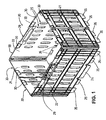
- Figure 1 shows a perspective view of a first embodiment of the invention;
- Figure 2 shows a more detailed view of a resilient tongue of in the assembly shown in Figure 1;
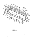
- Figure 3 shows a more detailed view of the outside of a handle of the assembly shown in figure 1;
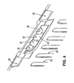
- Figure 4 shows a more detailed view of the inside of a handle of the assembly as shown in Figure 3;
- Figure 5 shows a perspective view of the assembly shown in Figure 1 in a semi-collapsed condition;
- Figure 6 shows a perspective view of a tray for use with the assembly shown in Figure 1;
- Figure 7 shows a perspective view of two enclosure assemblies of the type shown in Figure 1 and the tray shown in Figure 6, and;
- Figure 8 is a detailed view of the enclosure assemblies of Figure 7 in an attached condition.
- With reference to Figure 1 there is shown an
embodiment 20 of an enclosure assembly in accordance with the invention. Theenclosure assembly 20 is of oblong-rectangular shape and comprises twoend walls 21 and twoside walls 22. Each of thewalls elongate apertures 25 for venting. - The lower margin of the
assembly 20 comprises tworesilient tongues 24, one on eachside wall 22, and sixteen locatingtabs 26. - Each
side wall 22 is provided with a pair oftabs 26 on each side of thetongue 24, each pair oftabs 26 of eachside wall 22 being spaced in the direction of the thickness of the side wall. Similarly, eachend wall 21 comprises four locatingtabs 26. The two innermost tabs on each end wall being spaced from the two outermost tabs in the direction of the thickness of the wall. - Each
tongue 24 comprises an inwardly extendingprotrusion 28. Anotch feature 27 is provided in thewall 22 on each side of thetongue 24 to enhance the resilience of the tongue laterally of theenclosure assembly 20. - The uppermost margin of the
assembly 20 comprises twohandles 29 and sixteen tab receivingrecesses 30. Therecesses 30 are sized and arranged to receive thetabs 26 of asecond enclosure assembly 20. - Figures 3 and 4 show a
handle 29 in more detail. Eachhandle 29 comprises fourrecessed portions 32 of substantially circulate outline and five substantiallyflat surface portions 31, three of which are interposed between therecessed portions 32. Below each handle 29 arecess 33 is provided which is sufficiently large to allow the fingers of a person to pass there through. Each handle further comprises fiveouter ribs 37. - With reference to Figure 5, the
assembly 20 comprises fourcorner hinges 35 which are located at the interface between aside wall 22 and anend wall 21, and twohinges 36 which are located centrally of eachend wall 21. As seen in Figure 5, thehinges - Turning to Figure 6 there is shown a
tray 40 for use with theenclosure assembly 20. Thetray 40 comprises four walls, which walls are provided with twohandles 43. Thehandles 43 are substantially identical to thehandles 29 of theenclosure assembly 20. Therecesses 42 are sized and arranged to locate thetabs 26 of theenclosure assembly 20. - Figures 7 and 8 illustrate the use of the
enclosure assembly 20. together with thetray 40 and anenclosure assembly 50. Theenclosure assembly 50 is substantially identical toenclosure assembly 20, save for the fact thatassembly 50 is approximately twice as high as theassembly 20. - In use the
assembly 50 is initially pushed downwards into thetray 40 and in doing so the protrusions of the tongues on the lower margin contact with the outwardly facingribs 44 of each respective handle of thetray 40. Such contact urges the tongues to deflect generally outwardly of theassembly 50. With continual downward movement the tongues of theassembly 50 negotiate the handles and, by virtue of the inherent resilience of the tongues, the tongues 'snap' into a attached condition. Furthermore, in such an attached condition the tabs ofassembly 50 are located inrespective recesses 42 of thetray 40. Theassembly 50 is thus attached to thetray 40, and encloses a region thereabove. - Similarly, the
assembly 20 is then pushed downwards onto the upper margin of theassembly 50, so that theprotrusions 28 of theassembly 20 - Similarly, the
assembly 20 is then pushed downwards onto the upper margin of theassembly 50, so that theprotrusions 28 of theassembly 20 contact with theribs 54 and then snap into position under therespective handles 52 ofassembly 50, and thetabs 26 being located by the respective recesses on the upper margin of theassembly 50. - As can be seen in figure 8, in the attached condition of the
assembly 50 theprotrusion 28 of thetongue 24 is located under thehandle 52 and said protrusion bears againstflat surface portions 53 of thehandle 52. - The stacked arrangement of Figure 7 is particularly advantageous when the container holds tall goods, such as plants, the height of which is greater than that of an enclosure assembly, in which case a second enclosure assembly is attached onto a first enclosure assembly. Thus advantageously the same mechanism is used to attach an enclosure assembly to a container as to attach an enclosure assembly to another enclosure assembly.
- Advantageously the stacked enclosure assemblies form a substantially rigid structure the height of which can be chosen in accordance which the height of the goods to be transported.
- Advantageously, enclosure assemblies of different heights can be manufactured, but, importantly, comprising co-operable attachment means, which offer to a user an increased number of possible stack height configurations.
- Although specific reference has been made to a stack comprising only two enclosure assemblies it will be appreciated that a stack of three or more enclosure assemblies is possible depending on the height of the goods to be transported.
- Since both of the above described embodiments are collapsible to a substantially flat condition the assemblies can be readily stowed.
- It will be appreciated that in all of the embodiments hereinbefore described the co-operation between the attachment means of an upper enclosure assembly and the attachment means of a lower adjacent enclosure assembly or a lower adjacent container or tray is sufficient to suspend that lower assembly or container or tray when the upper enclosure assembly is lifted. The co-operation is desirably sufficient so that a stack of multiple enclosure assemblies and a container or tray (with the goods therein) can be lifted from one of the enclosure assemblies of the stack.
Claims (17)
- An enclosure assembly (20) which is adapted to be supported on a container (40) and in situ the enclosure assembly (20) encloses a region above the container, (40) said enclosure assembly (20) comprising co-operable attachment means (24) and handle means (29), the arrangement of the enclosure assembly (20) being such that in use the attachment means (24) of a first enclosure assembly (20) which is supported on a container (40) is engaged with the attachment means (24) of a second enclosure assembly (20), said enclosure assemblies (20) forming a stack in which the second enclosure assembly (20) encloses a region above the first enclosure assembly (20), the enclosure assembly (20) being characterised in that first attachment means (24) comprises protrusion means (28) and second attachment means comprises protrusion receiving means (33), the protrusion receiving means (33) being provided by a space which is sized to allow the fingers of a person to pass therethrough, and the space being provided below the handle means (29).
- An enclosure assembly (20) as claimed in claim 1 in which the enclosure assembly (20) is of substantially tubular form and the distal ends of which are open.
- An enclosure assembly (20) as claimed in claim 1 or claim 2 in which the first attachment means (24) is spaced from the second attachment means (33) in the direction of the height of the enclosure assembly.
- An enclosure assembly (20) as claimed in claim 3 in which the first attachment means (24) and the second attachment means (33) are located towards respective distal ends of the enclosure assembly (20).
- An enclosure assembly (20) as claimed in claim 4 in which the first attachment means (24) is located towards a lowermost margin of the enclosure assembly (20) the second attachment means (33) is located towards an uppermost margin of the enclosure assembly (20).
- An enclosure assembly (20) as claimed any preceding claim in which the first attachment means (24) of one enclosure assembly (20) is adapted to be engaged with the second attachment means (33) of another assembly (20).
- An enclosure assembly (20) as claimed in any preceding claim in which engagement between the first attachment means (24) and the second attachment means (33) is by way of a male-to-female engagement.
- An enclosure assembly (20) as claimed in any preceding claim in which the first attachment means (24) is adapted to engage with a container (40) so that the enclosure assembly (20) is secured to the container (40) to enclose a region above said container (40).
- An enclosure assembly (20) as claimed in any preceding claim in which the protrusion means (24) comprises a portion (28) which extends generally laterally of the enclosure assembly (20) and which portion (28) is adapted to be received by the protrusion receiving means (33).
- An enclosure assembly (20) as claimed in claim 9 in which the protrusion means (24) is of a tapered profile.
- An enclosure assembly (20) as claimed in claim 10 in which the tapered profile widens laterally of the enclosure assembly with increasing height of the enclosure assembly (20).
- An enclosure assembly (20) as claimed in any preceding claim in which the protrusion means (24) is provided secured to a resilient portion.
- An enclosure assembly (20) as claimed in claim 12 in which the resilient portion extends generally downwards of the enclosure assembly (20).
- An enclosure assembly (20) as claimed in claim 13 in which the resilient portion is adapted to be deflectable in a direction which is generally lateral of the enclosure assembly (20).
- An enclosure assembly (20) as claimed in any preceding claim which is of oblong-rectangular shape, protrusion means (24) being provided on opposite sides of the enclosure assembly (20).
- An enclosure assembly (20) as claimed in any preceding claim in which the first attachment means (24) comprises enclosure assembly attachment means and container attachment means, the enclosure assembly attachment means being physically distinct from the container attachment means.
- An enclosure assembly (20) as claimed in any preceding claim in which the attachment means is such that the stack and the container (40) may be lifted from the handle means (29).
Applications Claiming Priority (3)
| Application Number | Priority Date | Filing Date | Title |
|---|---|---|---|
| GB0113532 | 2001-06-05 | ||
| GBGB0113532.6A GB0113532D0 (en) | 2001-06-05 | 2001-06-05 | Enclosure assembly |
| PCT/GB2002/002569 WO2002098751A1 (en) | 2001-06-05 | 2002-05-31 | Enclosure assembly |
Publications (2)
| Publication Number | Publication Date |
|---|---|
| EP1392571A1 EP1392571A1 (en) | 2004-03-03 |
| EP1392571B1 true EP1392571B1 (en) | 2006-06-21 |
Family
ID=9915845
Family Applications (1)
| Application Number | Title | Priority Date | Filing Date |
|---|---|---|---|
| EP02732911A Expired - Lifetime EP1392571B1 (en) | 2001-06-05 | 2002-05-31 | Enclosure assembly |
Country Status (7)
| Country | Link |
|---|---|
| US (1) | US7562784B2 (en) |
| EP (1) | EP1392571B1 (en) |
| AT (1) | ATE330859T1 (en) |
| DE (1) | DE60212622T2 (en) |
| ES (1) | ES2265506T3 (en) |
| GB (1) | GB0113532D0 (en) |
| WO (1) | WO2002098751A1 (en) |
Families Citing this family (37)
| Publication number | Priority date | Publication date | Assignee | Title |
|---|---|---|---|---|
| DE10326574B4 (en) * | 2003-06-12 | 2007-09-27 | Ifco Systems Gmbh | Transport container system and attachment for a transport container system for general cargo, in particular for fruit and vegetables |
| GB0329487D0 (en) | 2003-12-22 | 2004-01-28 | Le Carton Ltd | Apparatus and method for assembling enclosure assemblies |
| GB2416529B (en) * | 2004-07-24 | 2008-02-13 | Linpac Mouldings Ltd | Collapsible container |
| GB0417317D0 (en) * | 2004-08-04 | 2004-09-08 | Le Carton Ltd | Enclosure assembly |
| DE102006041044A1 (en) * | 2006-09-01 | 2008-03-06 | Schoeller Arca Systems Services Gmbh | transport container |
| FR2921350B1 (en) * | 2007-09-26 | 2011-07-15 | Ds Smith Kaysersberg | CONTAINER WITH EMBEDDED BELTS IN CARDBOARD ONDULE |
| US9022241B2 (en) * | 2007-10-31 | 2015-05-05 | Lincoln Global, Inc. | Stackable container |
| US20090241809A1 (en) * | 2008-03-31 | 2009-10-01 | James Allen Head | Materials safety cage and associated methods |
| US20120067877A1 (en) * | 2010-09-21 | 2012-03-22 | Shaumil Dave | Collapsible carrying device |
| GB2501472A (en) * | 2012-04-23 | 2013-10-30 | Binyamin Mazoz | Reinforced container |
| KR101460972B1 (en) * | 2012-09-27 | 2014-11-21 | 인팩글로벌 주식회사 | folding multistage box for packing |
| US10450152B2 (en) | 2013-01-05 | 2019-10-22 | Trade Fixtures, Llc | Expandle gravity-feed bin |
| US10945537B2 (en) | 2013-01-05 | 2021-03-16 | Trade Fixtures, Llc | Expandable gravity-feed bin |
| US9872572B1 (en) | 2013-01-05 | 2018-01-23 | Trade Fixtures, Llc | Expandable gravity-feed bin |
| US9278788B2 (en) | 2013-01-05 | 2016-03-08 | Trade Fixtures, Llc | Expandable gravity-feed bin |
| CN105050906A (en) | 2013-01-05 | 2015-11-11 | 菲克斯彻贸易有限公司 | Expandable gravity-feed bin |
| DE102013106666A1 (en) * | 2013-06-26 | 2014-12-31 | Bs Systems Gmbh & Co. Kg | Attachment element for a stackable system box |
| US9783362B2 (en) | 2014-08-04 | 2017-10-10 | Christopher E. Boyea | Extender for receptacle and method thereof |
| US10450134B2 (en) | 2014-08-04 | 2019-10-22 | Christopher E. Boyea | Extender for receptacle and method thereof |
| JP5873156B1 (en) * | 2014-10-29 | 2016-03-01 | インパック グローバル カンパニー リミテッド | Packaging box |
| CN106864932A (en) * | 2017-04-26 | 2017-06-20 | 芜湖久恒包装科技有限公司 | A splicable turnover box with full monitoring |
| CN107264922A (en) * | 2017-06-22 | 2017-10-20 | 芜湖久恒包装科技有限公司 | A coaming box structure that is convenient for loading, unloading and recycling |
| CN107128599A (en) * | 2017-06-22 | 2017-09-05 | 芜湖久恒包装科技有限公司 | Loading, unloading, and recycling method for coaming box structure that is convenient for loading, unloading, and recycling |
| CZ32109U1 (en) * | 2017-11-27 | 2018-10-02 | Ppo Group Cz, S.R.O | A combined box for transportation and storage of goods |
| DE102018102960B4 (en) | 2018-02-09 | 2024-03-14 | TWIN-TEC Packaging GmbH | Attachment ring for a transport container, transport container and method for producing a attachment ring |
| US11548727B2 (en) | 2018-07-17 | 2023-01-10 | Christopher E. Boyea | Transformative extender and method thereof |
| TR201815732A2 (en) * | 2018-10-22 | 2018-11-21 | Fiyaka Plastik Ithalat Ihracat Sanayi Ve Ticaret Anonim Sirketi | A TRANSPORT SYSTEM |
| US11951893B2 (en) * | 2020-12-23 | 2024-04-09 | Ford Global Technologies, Llc | Interlocking reconfigurable modular lockers |
| US12617581B2 (en) * | 2024-06-07 | 2026-05-05 | Shuert Technology, Llc | System using clips for joining container sleeves |
| TWD241930S (en) * | 2024-10-14 | 2025-12-11 | 聯府塑膠股份有限公司 苗栗縣銅鑼鄉銅鑼村自強路18號 (中華民國) | Side panel of folding stroller |
| TWD241933S (en) * | 2024-10-14 | 2025-12-11 | 聯府塑膠股份有限公司 苗栗縣銅鑼鄉銅鑼村自強路18號 (中華民國) | Side panel of folding stroller |
| TWD241931S (en) * | 2024-10-14 | 2025-12-11 | 聯府塑膠股份有限公司 苗栗縣銅鑼鄉銅鑼村自強路18號 (中華民國) | Side panel of folding stroller |
| TWD244989S (en) * | 2025-05-02 | 2026-06-11 | 聯府塑膠股份有限公司 苗栗縣銅鑼鄉銅鑼村自強路18號 (中華民國) | Side panel of folding stroller |
| TWD244987S (en) * | 2025-05-02 | 2026-06-11 | 聯府塑膠股份有限公司 苗栗縣銅鑼鄉銅鑼村自強路18號 (中華民國) | Side panel of folding stroller |
| JP1827623S (en) * | 2025-06-27 | 2026-05-25 | Folding container cart side panel | |
| JP1827625S (en) * | 2025-07-04 | 2026-05-25 | Folding container cart side panel | |
| JP1827626S (en) * | 2025-07-04 | 2026-05-25 | Folding container cart side panel |
Family Cites Families (10)
| Publication number | Priority date | Publication date | Assignee | Title |
|---|---|---|---|---|
| GB1117448A (en) | 1964-07-22 | 1968-06-19 | Kearney Persn Services A T | Improvements in or relating to freight binding devices |
| US3581932A (en) * | 1969-04-29 | 1971-06-01 | Pinckney Molded Plastics | Nest and stack containers |
| US4079836A (en) * | 1975-11-12 | 1978-03-21 | Folding Carrier Corporation, A Division Of Unarco Industries, Inc. | Baskets and support therefor, for mass merchandising handling and display of goods |
| US4212415A (en) * | 1978-01-09 | 1980-07-15 | Refreshment Machinery Incorporated | Housing and module therefor |
| DE4037696A1 (en) | 1990-10-26 | 1992-04-30 | Schoeller Plast Ag | CONTAINER SYSTEM, ESPECIALLY TRANSPORT, AND / OR PACKAGING CONTAINER SYSTEM |
| US5123537A (en) * | 1991-04-03 | 1992-06-23 | Fellowes Manufacturing Company | Tray stacking system |
| NL9300986A (en) | 1993-06-08 | 1995-01-02 | Wavin Bv | Container which can be assembled |
| US5544751A (en) * | 1995-05-03 | 1996-08-13 | Flambeau Products Corp. | Stacking connector for storage container |
| FR2805528B1 (en) | 2000-02-29 | 2002-05-17 | Krustanord | PACKAGING SYSTEM |
| US7014043B2 (en) * | 2001-01-15 | 2006-03-21 | Norseman Plastics, Limited | Multi-level stacking container |
-
2001
- 2001-06-05 GB GBGB0113532.6A patent/GB0113532D0/en not_active Ceased
-
2002
- 2002-05-31 AT AT02732911T patent/ATE330859T1/en not_active IP Right Cessation
- 2002-05-31 DE DE60212622T patent/DE60212622T2/en not_active Expired - Lifetime
- 2002-05-31 ES ES02732911T patent/ES2265506T3/en not_active Expired - Lifetime
- 2002-05-31 WO PCT/GB2002/002569 patent/WO2002098751A1/en not_active Ceased
- 2002-05-31 US US10/479,766 patent/US7562784B2/en not_active Expired - Fee Related
- 2002-05-31 EP EP02732911A patent/EP1392571B1/en not_active Expired - Lifetime
Also Published As
| Publication number | Publication date |
|---|---|
| WO2002098751A1 (en) | 2002-12-12 |
| GB0113532D0 (en) | 2001-07-25 |
| EP1392571A1 (en) | 2004-03-03 |
| ES2265506T3 (en) | 2007-02-16 |
| ATE330859T1 (en) | 2006-07-15 |
| DE60212622D1 (en) | 2006-08-03 |
| DE60212622T2 (en) | 2007-07-05 |
| US20040211776A1 (en) | 2004-10-28 |
| US7562784B2 (en) | 2009-07-21 |
Similar Documents
| Publication | Publication Date | Title |
|---|---|---|
| US7562784B2 (en) | Enclosure assembly | |
| US8596487B1 (en) | Carrier unit for carrying parts boxes | |
| US6713029B1 (en) | Sterilization tray | |
| PL206490B1 (en) | Shipping container | |
| US20170008669A1 (en) | Three tiered tray | |
| KR980009049A (en) | Storage containers | |
| US8056723B2 (en) | Collapsible container | |
| AU2004274301A1 (en) | Article storage case | |
| US10450104B2 (en) | Storage tote with latching handle | |
| WO2005097516A3 (en) | Nestable and stackable document storage trays | |
| US20060096883A1 (en) | Multi-level stacking container | |
| EP2289811B1 (en) | Collapsible crate | |
| US20160272369A1 (en) | Containing Box Structure | |
| US20190239639A1 (en) | Compact shelf assembly | |
| EP3517004B1 (en) | Containing device having slidable handle | |
| US4830189A (en) | Container | |
| IE47668B1 (en) | Plastics tray | |
| KR200453733Y1 (en) | Disposable food packaging | |
| US6662949B2 (en) | Package for mechanical or electrical components | |
| US20040163971A1 (en) | Modular container | |
| WO2021240304A1 (en) | Stackable container | |
| KR100885680B1 (en) | Stackable and Stackable Carry Box | |
| US7438185B2 (en) | Stackable tray with integral latch | |
| GB2416762A (en) | Detachable enclosure assembly for a container | |
| US12492040B2 (en) | Stackable and nestable container |
Legal Events
| Date | Code | Title | Description |
|---|---|---|---|
| PUAI | Public reference made under article 153(3) epc to a published international application that has entered the european phase |
Free format text: ORIGINAL CODE: 0009012 |
|
| 17P | Request for examination filed |
Effective date: 20031208 |
|
| AK | Designated contracting states |
Kind code of ref document: A1 Designated state(s): AT BE CH CY DE DK ES FI FR GB GR IE IT LI LU MC NL PT SE TR |
|
| AX | Request for extension of the european patent |
Extension state: AL LT LV MK RO SI |
|
| GRAP | Despatch of communication of intention to grant a patent |
Free format text: ORIGINAL CODE: EPIDOSNIGR1 |
|
| GRAC | Information related to communication of intention to grant a patent modified |
Free format text: ORIGINAL CODE: EPIDOSCIGR1 |
|
| GRAS | Grant fee paid |
Free format text: ORIGINAL CODE: EPIDOSNIGR3 |
|
| GRAA | (expected) grant |
Free format text: ORIGINAL CODE: 0009210 |
|
| AK | Designated contracting states |
Kind code of ref document: B1 Designated state(s): AT BE CH CY DE DK ES FI FR GB GR IE IT LI LU MC NL PT SE TR |
|
| PG25 | Lapsed in a contracting state [announced via postgrant information from national office to epo] |
Ref country code: IT Free format text: LAPSE BECAUSE OF FAILURE TO SUBMIT A TRANSLATION OF THE DESCRIPTION OR TO PAY THE FEE WITHIN THE PRESCRIBED TIME-LIMIT;WARNING: LAPSES OF ITALIAN PATENTS WITH EFFECTIVE DATE BEFORE 2007 MAY HAVE OCCURRED AT ANY TIME BEFORE 2007. THE CORRECT EFFECTIVE DATE MAY BE DIFFERENT FROM THE ONE RECORDED. Effective date: 20060621 Ref country code: AT Free format text: LAPSE BECAUSE OF FAILURE TO SUBMIT A TRANSLATION OF THE DESCRIPTION OR TO PAY THE FEE WITHIN THE PRESCRIBED TIME-LIMIT Effective date: 20060621 Ref country code: FI Free format text: LAPSE BECAUSE OF FAILURE TO SUBMIT A TRANSLATION OF THE DESCRIPTION OR TO PAY THE FEE WITHIN THE PRESCRIBED TIME-LIMIT Effective date: 20060621 Ref country code: CH Free format text: LAPSE BECAUSE OF FAILURE TO SUBMIT A TRANSLATION OF THE DESCRIPTION OR TO PAY THE FEE WITHIN THE PRESCRIBED TIME-LIMIT Effective date: 20060621 Ref country code: BE Free format text: LAPSE BECAUSE OF FAILURE TO SUBMIT A TRANSLATION OF THE DESCRIPTION OR TO PAY THE FEE WITHIN THE PRESCRIBED TIME-LIMIT Effective date: 20060621 Ref country code: LI Free format text: LAPSE BECAUSE OF FAILURE TO SUBMIT A TRANSLATION OF THE DESCRIPTION OR TO PAY THE FEE WITHIN THE PRESCRIBED TIME-LIMIT Effective date: 20060621 |
|
| REG | Reference to a national code |
Ref country code: GB Ref legal event code: FG4D |
|
| REG | Reference to a national code |
Ref country code: CH Ref legal event code: EP |
|
| REG | Reference to a national code |
Ref country code: IE Ref legal event code: FG4D |
|
| REF | Corresponds to: |
Ref document number: 60212622 Country of ref document: DE Date of ref document: 20060803 Kind code of ref document: P |
|
| PG25 | Lapsed in a contracting state [announced via postgrant information from national office to epo] |
Ref country code: DK Free format text: LAPSE BECAUSE OF FAILURE TO SUBMIT A TRANSLATION OF THE DESCRIPTION OR TO PAY THE FEE WITHIN THE PRESCRIBED TIME-LIMIT Effective date: 20060921 Ref country code: SE Free format text: LAPSE BECAUSE OF FAILURE TO SUBMIT A TRANSLATION OF THE DESCRIPTION OR TO PAY THE FEE WITHIN THE PRESCRIBED TIME-LIMIT Effective date: 20060921 |
|
| PG25 | Lapsed in a contracting state [announced via postgrant information from national office to epo] |
Ref country code: PT Free format text: LAPSE BECAUSE OF FAILURE TO SUBMIT A TRANSLATION OF THE DESCRIPTION OR TO PAY THE FEE WITHIN THE PRESCRIBED TIME-LIMIT Effective date: 20061121 |
|
| REG | Reference to a national code |
Ref country code: CH Ref legal event code: PL |
|
| ET | Fr: translation filed | ||
| REG | Reference to a national code |
Ref country code: ES Ref legal event code: FG2A Ref document number: 2265506 Country of ref document: ES Kind code of ref document: T3 |
|
| PLBE | No opposition filed within time limit |
Free format text: ORIGINAL CODE: 0009261 |
|
| STAA | Information on the status of an ep patent application or granted ep patent |
Free format text: STATUS: NO OPPOSITION FILED WITHIN TIME LIMIT |
|
| 26N | No opposition filed |
Effective date: 20070322 |
|
| PG25 | Lapsed in a contracting state [announced via postgrant information from national office to epo] |
Ref country code: MC Free format text: LAPSE BECAUSE OF NON-PAYMENT OF DUE FEES Effective date: 20070531 |
|
| PG25 | Lapsed in a contracting state [announced via postgrant information from national office to epo] |
Ref country code: GR Free format text: LAPSE BECAUSE OF FAILURE TO SUBMIT A TRANSLATION OF THE DESCRIPTION OR TO PAY THE FEE WITHIN THE PRESCRIBED TIME-LIMIT Effective date: 20060922 |
|
| PG25 | Lapsed in a contracting state [announced via postgrant information from national office to epo] |
Ref country code: IE Free format text: LAPSE BECAUSE OF NON-PAYMENT OF DUE FEES Effective date: 20070531 |
|
| PG25 | Lapsed in a contracting state [announced via postgrant information from national office to epo] |
Ref country code: LU Free format text: LAPSE BECAUSE OF NON-PAYMENT OF DUE FEES Effective date: 20070531 Ref country code: CY Free format text: LAPSE BECAUSE OF FAILURE TO SUBMIT A TRANSLATION OF THE DESCRIPTION OR TO PAY THE FEE WITHIN THE PRESCRIBED TIME-LIMIT Effective date: 20060621 |
|
| PGFP | Annual fee paid to national office [announced via postgrant information from national office to epo] |
Ref country code: IT Payment date: 20090527 Year of fee payment: 8 |
|
| PG25 | Lapsed in a contracting state [announced via postgrant information from national office to epo] |
Ref country code: TR Free format text: LAPSE BECAUSE OF FAILURE TO SUBMIT A TRANSLATION OF THE DESCRIPTION OR TO PAY THE FEE WITHIN THE PRESCRIBED TIME-LIMIT Effective date: 20060621 |
|
| PGFP | Annual fee paid to national office [announced via postgrant information from national office to epo] |
Ref country code: ES Payment date: 20100521 Year of fee payment: 9 Ref country code: FR Payment date: 20100610 Year of fee payment: 9 |
|
| PGFP | Annual fee paid to national office [announced via postgrant information from national office to epo] |
Ref country code: DE Payment date: 20100726 Year of fee payment: 9 |
|
| PG25 | Lapsed in a contracting state [announced via postgrant information from national office to epo] |
Ref country code: IT Free format text: LAPSE BECAUSE OF NON-PAYMENT OF DUE FEES Effective date: 20100531 |
|
| REG | Reference to a national code |
Ref country code: FR Ref legal event code: ST Effective date: 20120131 |
|
| REG | Reference to a national code |
Ref country code: DE Ref legal event code: R119 Ref document number: 60212622 Country of ref document: DE Effective date: 20111201 |
|
| PG25 | Lapsed in a contracting state [announced via postgrant information from national office to epo] |
Ref country code: FR Free format text: LAPSE BECAUSE OF NON-PAYMENT OF DUE FEES Effective date: 20110531 |
|
| PG25 | Lapsed in a contracting state [announced via postgrant information from national office to epo] |
Ref country code: DE Free format text: LAPSE BECAUSE OF NON-PAYMENT OF DUE FEES Effective date: 20111201 |
|
| REG | Reference to a national code |
Ref country code: GB Ref legal event code: 732E Free format text: REGISTERED BETWEEN 20130704 AND 20130710 |
|
| REG | Reference to a national code |
Ref country code: ES Ref legal event code: FD2A Effective date: 20131029 |
|
| PG25 | Lapsed in a contracting state [announced via postgrant information from national office to epo] |
Ref country code: ES Free format text: LAPSE BECAUSE OF NON-PAYMENT OF DUE FEES Effective date: 20110601 |
|
| PGFP | Annual fee paid to national office [announced via postgrant information from national office to epo] |
Ref country code: NL Payment date: 20160531 Year of fee payment: 15 |
|
| REG | Reference to a national code |
Ref country code: NL Ref legal event code: MM Effective date: 20170601 |
|
| PG25 | Lapsed in a contracting state [announced via postgrant information from national office to epo] |
Ref country code: NL Free format text: LAPSE BECAUSE OF NON-PAYMENT OF DUE FEES Effective date: 20170601 |
|
| PGFP | Annual fee paid to national office [announced via postgrant information from national office to epo] |
Ref country code: GB Payment date: 20201221 Year of fee payment: 19 |
|
| GBPC | Gb: european patent ceased through non-payment of renewal fee |
Effective date: 20210531 |
|
| PG25 | Lapsed in a contracting state [announced via postgrant information from national office to epo] |
Ref country code: GB Free format text: LAPSE BECAUSE OF NON-PAYMENT OF DUE FEES Effective date: 20210531 |