EP1391976A2 - Air-cooled motor - Google Patents
Air-cooled motor Download PDFInfo
- Publication number
- EP1391976A2 EP1391976A2 EP03255108A EP03255108A EP1391976A2 EP 1391976 A2 EP1391976 A2 EP 1391976A2 EP 03255108 A EP03255108 A EP 03255108A EP 03255108 A EP03255108 A EP 03255108A EP 1391976 A2 EP1391976 A2 EP 1391976A2
- Authority
- EP
- European Patent Office
- Prior art keywords
- cylindrical member
- air
- supply section
- fluid
- hole
- Prior art date
- Legal status (The legal status is an assumption and is not a legal conclusion. Google has not performed a legal analysis and makes no representation as to the accuracy of the status listed.)
- Granted
Links
Images


Classifications
-
- H—ELECTRICITY
- H02—GENERATION; CONVERSION OR DISTRIBUTION OF ELECTRIC POWER
- H02K—DYNAMO-ELECTRIC MACHINES
- H02K7/00—Arrangements for handling mechanical energy structurally associated with dynamo-electric machines, e.g. structural association with mechanical driving motors or auxiliary dynamo-electric machines
-
- H—ELECTRICITY
- H02—GENERATION; CONVERSION OR DISTRIBUTION OF ELECTRIC POWER
- H02K—DYNAMO-ELECTRIC MACHINES
- H02K5/00—Casings; Enclosures; Supports
- H02K5/04—Casings or enclosures characterised by the shape, form or construction thereof
-
- H—ELECTRICITY
- H02—GENERATION; CONVERSION OR DISTRIBUTION OF ELECTRIC POWER
- H02K—DYNAMO-ELECTRIC MACHINES
- H02K5/00—Casings; Enclosures; Supports
- H02K5/04—Casings or enclosures characterised by the shape, form or construction thereof
- H02K5/20—Casings or enclosures characterised by the shape, form or construction thereof with channels or ducts for flow of cooling medium
- H02K5/207—Casings or enclosures characterised by the shape, form or construction thereof with channels or ducts for flow of cooling medium with openings in the casing specially adapted for ambient air
-
- H—ELECTRICITY
- H02—GENERATION; CONVERSION OR DISTRIBUTION OF ELECTRIC POWER
- H02K—DYNAMO-ELECTRIC MACHINES
- H02K9/00—Arrangements for cooling or ventilating
- H02K9/02—Arrangements for cooling or ventilating by ambient air flowing through the machine
- H02K9/04—Arrangements for cooling or ventilating by ambient air flowing through the machine having means for generating a flow of cooling medium
-
- H—ELECTRICITY
- H02—GENERATION; CONVERSION OR DISTRIBUTION OF ELECTRIC POWER
- H02K—DYNAMO-ELECTRIC MACHINES
- H02K9/00—Arrangements for cooling or ventilating
- H02K9/02—Arrangements for cooling or ventilating by ambient air flowing through the machine
- H02K9/04—Arrangements for cooling or ventilating by ambient air flowing through the machine having means for generating a flow of cooling medium
- H02K9/06—Arrangements for cooling or ventilating by ambient air flowing through the machine having means for generating a flow of cooling medium with fans or impellers driven by the machine shaft
-
- H—ELECTRICITY
- H02—GENERATION; CONVERSION OR DISTRIBUTION OF ELECTRIC POWER
- H02K—DYNAMO-ELECTRIC MACHINES
- H02K9/00—Arrangements for cooling or ventilating
- H02K9/19—Arrangements for cooling or ventilating for machines with closed casing and closed-circuit cooling using a liquid cooling medium, e.g. oil
- H02K9/197—Arrangements for cooling or ventilating for machines with closed casing and closed-circuit cooling using a liquid cooling medium, e.g. oil in which the rotor or stator space is fluid-tight, e.g. to provide for different cooling media for rotor and stator
-
- H—ELECTRICITY
- H02—GENERATION; CONVERSION OR DISTRIBUTION OF ELECTRIC POWER
- H02K—DYNAMO-ELECTRIC MACHINES
- H02K9/00—Arrangements for cooling or ventilating
- H02K9/24—Protection against failure of cooling arrangements, e.g. due to loss of cooling medium or due to interruption of the circulation of cooling medium
-
- H—ELECTRICITY
- H02—GENERATION; CONVERSION OR DISTRIBUTION OF ELECTRIC POWER
- H02K—DYNAMO-ELECTRIC MACHINES
- H02K7/00—Arrangements for handling mechanical energy structurally associated with dynamo-electric machines, e.g. structural association with mechanical driving motors or auxiliary dynamo-electric machines
- H02K7/003—Couplings; Details of shafts
Definitions
- the present invention relates to an air-cooled motor and, more particularly, to an air-cooled motor in which a through hole for passing a fluid is provided in a rotary shaft.
- a motor in which a through hole is formed in the rotary shaft is widely used (for example, refer to Japanese Patent Application Laid-Open No. 10-146021).
- the motor of this type has a hole for passing a liquid or gas, which is formed so as to extend through the rotary shaft, and has a supply section using a rotary joint at the end of the shaft on the rear side of the motor in order to supply the liquid or gas into the through hole.
- an air cooling type is often used to cool down the motor body.
- a structure commonly employed is that the exhaust direction of cooling air is set to the axial direction of the motor (the direction in which the rotary shaft extends), and the cooling fan is attached to the rear side of the motor. Therefore, the cooling air for cooling the motor body passes around the supply section in which the rotary joint is provided and reaches the cooling fan.
- a structure is generally employed such that the rotary joint is covered with a cylindrical member called a distance block and the cooling fan is attached to the rear end face of the cylindrical member.
- An object of the invention is therefore to provide an air-cooled motor which solves the problems of the conventional technique and of which supply section (rotary joint) to a through hole and the periphery of the supply section can be visually observed so that an abnormal state of the supply section (rotary joint), a liquid leakage, or the like can be found early.
- the invention is applied to an air-cooled motor having: a motor body in which a through hole is formed in a rotary shaft; a supply section for supplying a fluid to the through hole; a cylindrical member surrounding the supply section; and a cooling fan provided on the side opposite the motor body with respect to the cylindrical member.
- a window is provided in the cylindrical member so that the supply section can be visually observed. At least a part of the cylindrical member may be made of a transparent material so that the supply section can be visually observed. Further, a passage for distributing cooling air toward the cooling fan may be provided in the cylindrical member.
- the supply section can be visually observed without providing openings in the cylindrical member.
- the cylindrical member itself can be used as means for assuring a passage of cooling air in a manner similar to the conventional technique.
- the cylindrical member in the case of providing a passage for distributing cooling air toward the cooling fan in the cylindrical member, even when an opening is formed in the cylindrical member for using it as a "window", there is no worry that the air cooling efficiency of the motor body deteriorates. Since the number of the openings increases, heat dissipation is promoted.
- FIG. 1 is a cross section of main components of an air-cooled motor according to a first embodiment of the invention.
- reference numeral 1 denotes a motor body having a through hole 10 in a rotary shaft.
- a rotary joint attachment housing 2 is provided, and a rotary joint 3 is attached to the rotary joint attachment housing 2.
- the rotary joint 3 constructs a fluid supply section for supplying a fluid (liquid or gas) from a stationary portion side to the through hole 10 formed in the rotary shaft.
- a hose (fluid feeding tube) 11 is connected to the rotary joint (fluid supply section) 3. Via the hose (fluid feeding tube) 11, fluid is fed to the rotary joint (fluid supply section) 3.
- the main shaft of a processing machine having a through hole on the same rotary axis as the through hole 10 is connected to the front end side of the rotary shaft of the motor via a joint, a processing tool with a through hole. is attached to the front end of the main shaft, and the fluid fed via the rotary joint (fluid supply section) 3 into the through hole 10 passes through the through hole of the main shaft and the through hole of the processing tool and is sprayed to a process region of a workpiece to be processed.
- the process region is cooled by the fluid, so that overheating is prevented, and also an efficient discharge of chips is performed.
- cooling air passages 13 are provided in proper places in the motor body 1 and a cooling fan 4 is disposed on the rear side of the rotary joint 3.
- the cooling air passages 13 are open to the outside in proper places in the front portion of the motor body 1 in order to take in the outside air.
- the space around the fluid supply section (rotary joint) 3 interposed between the cooling fan 4 and the motor body 1 is surrounded by a cylindrical member 20 detachably attached to the rear end side of the motor body 1.
- the cylindrical member 20 is also called a distance block.
- the cylindrical member (distance block) 20 itself provides a cooling air passage extending between the cooling fan 4 and the motor body 1.
- the portion around the rotary joint (fluid supply section) 3 can be easily visually observed from the outside, by forming a part of the cylindrical member (distance block) 20 by a transparent member 21.
- the transparent member 21 is made of, for example, transparent acrylic resin, glass, or the like and forms an observation window having four corners a, b, c, and d.
- the transparent member 21 is provided so as to close the portion defined by the reference characters a, b, c, and d without creating a gap, so that the outside air is not taken in through the observation window and the air cooling efficiency does not deteriorate. It is preferable to detachably attach the transparent member 21 to the cylindrical member (distance block) 20.
- the operator When the leaked fluid is accumulated in the cylindrical member 20 when a large amount of fluid leaks due to breakage of the rotary joint 3, the operator immediately turns off the power of the motor, detaches the transparent member 21 and the cylindrical member 20 and discharge the accumulated fluid. The operator also takes necessary steps such as replacement of the broken rotary joint.
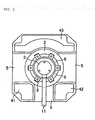
- FIG. 2 is a diagram showing a portion around the rear portion of the air-cooled motor according to the second embodiment.
- FIG. 3 is a cross section taken along line B-B in the air-cooled motor shown in FIG. 2.
- the rotary joint attachment housing 2 is provided on the rear side of the motor body 1 having the through hole 10 in the rotary shaft, and the rotary joint 3 is attached to the rotary joint attachment housing 2.
- Reference numeral 8 denotes legs of the rotary joint attachment housing 2 and, by using the legs 8, the rotary joint attachment housing 2 is attached to the rear portion of the motor body 1.
- Reference numeral 6 denotes openings (notches) formed in plural portions in the rotary joint attachment housing 2 and, as described later. When a fluid leakage occurs due to breakage or the like of the rotary joint 3, the openings 6 provide an escape of a leaked fluid.
- the rotary joint 3 constitutes the fluid supply section for supplying a fluid (liquid or gas) from the stationary portion side to the through hole 10 formed through the rotary shaft.
- the hose (fluid feeding tube) 11 is connected to the rotary joint (fluid supply section) 3, and the fluid is fed into the rotary joint (fluid supply section) 3 via the hose (fluid feeding tube) 11.
- FIG. 2 the rear end of the rotary shaft having the through hole 10 is shown by reference numeral 15.
- the main shaft of a processing machine having a through hole which is coaxial with the through hole 10 is connected via a joint to the front end side of the rotary shaft of the motor.
- a processing tool with a through hole is attached to the front end of the main shaft, and the fluid fed into the through hole 10 via the rotary joint (fluid supply section) 3 passes through the through hole in the main shaft and the through hole in the processing tool and is sprayed to the process region in the workpiece to be processed.
- the process region is cooled down by the fluid, so that overheating is prevented, and also an efficient discharge of chips is performed.
- cooling air passages are provided in proper places in the motor body 1 and the cooling fan 4 is disposed on the rear side of the rotary joint 3.
- the cooling air passages in the motor body 1 are open to the outside in proper places in the front part of the motor body 1 to take in the outside air. Since the cooling air passages provided in the motor body 1 are similar to those in the foregoing embodiment described with reference to FIG. 1, the detailed description will not be repeated and the cooling air passages are not shown here.
- the space around the fluid supply section (rotary joint) 3 interposed between the cooling fan 4 and the motor body 1 is surrounded by a cylindrical member 30 detachably attached to the rear end side of the motor body 1.
- the cylindrical member 30 has, different from the cylindrical member 20 used in the foregoing embodiment (FIG. 1), windows 5 opened to the sides with respect to the axial direction of the motor (extending direction of the rotary shaft) in some places.
- cooling air passages 41, 42, and 43 are integrally provided on the inside of the cylindrical member (distance block) 30 so that they are used as a cooling air passage portion.
- the cooling air passage portion for assuring the cooling air passage may be formed by a member (pipe) which is different from the cylindrical member 30.
- the portion around the rotary joint (fluid supply section) 3 can be easily visually observed from the outside.
- the fluid passes through the openings (notches) 6 formed in some places in the rotary joint attachment housing 2 and the opened windows 5 through which air can be ventilated and flows to the outside.
- the structure such that the fluid supply section (rotary joint) to the through hole and its periphery can be visually observed is provided while assuring the passage of the cooling air for air-cooling. It facilitates early finding of an abnormal state of the fluid supply section using a rotary joint, a fluid leakage, and the like.
Landscapes
- Engineering & Computer Science (AREA)
- Power Engineering (AREA)
- Motor Or Generator Cooling System (AREA)
- Motor Or Generator Frames (AREA)
- Iron Core Of Rotating Electric Machines (AREA)
Abstract
Description
Claims (4)
- An air-cooled motor comprising:wherein a window is provided in the cylindrical member so that the supply section can be visually observed.a motor body in which a through hole is formed in a rotary shaft;a supply section for supplying a fluid to the through hole;a cylindrical member surrounding the supply section; anda cooling fan provided on the side opposite the motor body with respect to the cylindrical member,
- The air-cooled motor according to claim 1, wherein a passage for distributing cooling air toward the cooling fan is provided in the cylindrical member.
- An air-cooled motor comprising:wherein at least a part of the cylindrical member is made of a transparent material so that the supply section can be visually observed.a motor body in which a through hole is formed in a rotary shaft;a supply section for supplying a fluid to the through hole;a cylindrical member surrounding the supply section; anda cooling fan provided on the side opposite the motor body with respect to the cylindrical member,
- The air-cooled motor according to claim 3, wherein a passage for distributing cooling air toward the cooling fan is provided in the cylindrical member.
Applications Claiming Priority (2)
| Application Number | Priority Date | Filing Date | Title |
|---|---|---|---|
| JP2002244109 | 2002-08-23 | ||
| JP2002244109A JP3650613B2 (en) | 2002-08-23 | 2002-08-23 | Air-cooled electric motor |
Publications (3)
| Publication Number | Publication Date |
|---|---|
| EP1391976A2 true EP1391976A2 (en) | 2004-02-25 |
| EP1391976A3 EP1391976A3 (en) | 2005-02-02 |
| EP1391976B1 EP1391976B1 (en) | 2007-11-14 |
Family
ID=31185243
Family Applications (1)
| Application Number | Title | Priority Date | Filing Date |
|---|---|---|---|
| EP03255108A Expired - Lifetime EP1391976B1 (en) | 2002-08-23 | 2003-08-18 | Air-cooled motor |
Country Status (4)
| Country | Link |
|---|---|
| US (1) | US6940192B2 (en) |
| EP (1) | EP1391976B1 (en) |
| JP (1) | JP3650613B2 (en) |
| DE (1) | DE60317418T2 (en) |
Families Citing this family (8)
| Publication number | Priority date | Publication date | Assignee | Title |
|---|---|---|---|---|
| JP4297859B2 (en) * | 2004-09-28 | 2009-07-15 | 三洋電機株式会社 | HUB UNIT FOR ELECTRIC WHEEL AND VEHICLE HAVING THE HUB UNIT |
| US20110089777A1 (en) * | 2009-10-18 | 2011-04-21 | Ernesto Camilo Rivera | Thermally manageable system and electric device |
| JP5429216B2 (en) * | 2011-03-16 | 2014-02-26 | 株式会社安川電機 | Rotating electrical machine air duct and rotating electrical machine unit |
| US9653967B2 (en) | 2013-03-15 | 2017-05-16 | Techtronic Power Tools Technology Limited | Cooling arrangement for an electric motor |
| US9973049B2 (en) | 2013-03-15 | 2018-05-15 | Techtronic Industries Co. Ltd. | Electric motor |
| US10178997B2 (en) * | 2014-09-24 | 2019-01-15 | Gyrus Acmi, Inc. | High-speed powered hand tool with improved motor cooling |
| JP6474441B2 (en) | 2017-03-10 | 2019-02-27 | ファナック株式会社 | Electric motors and machine tools |
| JP6937967B1 (en) * | 2020-12-01 | 2021-09-22 | 三菱電機株式会社 | Rotating machine |
Family Cites Families (20)
| Publication number | Priority date | Publication date | Assignee | Title |
|---|---|---|---|---|
| US1575660A (en) * | 1922-10-26 | 1926-03-09 | Mancha Storage Battery Locomot | Motor housing |
| JPS5625337Y2 (en) * | 1976-02-10 | 1981-06-15 | ||
| US4574210A (en) * | 1983-07-07 | 1986-03-04 | Wilhelm Gebhardt Gmbh | External rotor motor having a cooling system |
| JPS6162544A (en) | 1984-09-03 | 1986-03-31 | Mitsubishi Chem Ind Ltd | Resin composition |
| JPS6162542A (en) | 1984-09-04 | 1986-03-31 | Sumitomo Chem Co Ltd | Thermoplastic resin composition |
| NO167489C (en) * | 1985-02-11 | 1991-11-06 | Siemens Ag | RETURN FITTED TRIANGLE FIELD MACHINE WITH ELECTRONIC SETTING BODY |
| JPS6219059A (en) | 1985-07-15 | 1987-01-27 | Nisshin Flour Milling Co Ltd | Frozen noodle |
| US5019733A (en) * | 1987-09-25 | 1991-05-28 | Honda Giken Kogyo Kabushiki Kaisha | AC generator |
| JPH0285093A (en) | 1988-06-09 | 1990-03-26 | Shipbuild Res Assoc Japan | Sludge recovering device |
| JPH0810976B2 (en) | 1989-01-25 | 1996-01-31 | ファナック株式会社 | Liquid cooling structure of motor |
| JPH0456988A (en) | 1990-06-26 | 1992-02-24 | Furuno Electric Co Ltd | In-figure character display device |
| JPH05324407A (en) | 1992-05-26 | 1993-12-07 | Nec Corp | Cpu monitor system |
| US5589720A (en) * | 1992-09-10 | 1996-12-31 | Elin Motoren Gmbh | Electric motor with cooling device |
| JP2966799B2 (en) | 1996-11-07 | 1999-10-25 | ファナック株式会社 | Air-cooled motor |
| US6087744A (en) * | 1997-08-26 | 2000-07-11 | Robert Bosch Gmbh | Electrical machine |
| JPH11179631A (en) * | 1997-12-18 | 1999-07-06 | Fanuc Ltd | Spindle protecting structure in spindle through coolant |
| JP4175584B2 (en) * | 1998-09-11 | 2008-11-05 | 油研工業株式会社 | Motor-integrated hydraulic pump device |
| EP0989658A1 (en) * | 1998-09-28 | 2000-03-29 | The Swatch Group Management Services AG | Liquid-cooled aynchronous electric machine |
| US5994804A (en) * | 1998-12-07 | 1999-11-30 | Sundstrand Corporation | Air cooled dynamoelectric machine |
| US6727609B2 (en) * | 2001-08-08 | 2004-04-27 | Hamilton Sundstrand Corporation | Cooling of a rotor for a rotary electric machine |
-
2002
- 2002-08-23 JP JP2002244109A patent/JP3650613B2/en not_active Expired - Lifetime
-
2003
- 2003-08-18 EP EP03255108A patent/EP1391976B1/en not_active Expired - Lifetime
- 2003-08-18 DE DE60317418T patent/DE60317418T2/en not_active Expired - Lifetime
- 2003-08-20 US US10/643,872 patent/US6940192B2/en not_active Expired - Lifetime
Also Published As
| Publication number | Publication date |
|---|---|
| US6940192B2 (en) | 2005-09-06 |
| EP1391976B1 (en) | 2007-11-14 |
| DE60317418D1 (en) | 2007-12-27 |
| US20040036366A1 (en) | 2004-02-26 |
| JP3650613B2 (en) | 2005-05-25 |
| EP1391976A3 (en) | 2005-02-02 |
| DE60317418T2 (en) | 2008-09-11 |
| JP2004088850A (en) | 2004-03-18 |
Similar Documents
| Publication | Publication Date | Title |
|---|---|---|
| US5356245A (en) | Cooling and dust collecting apparatus for a machine tool | |
| EP0864728A2 (en) | Blade cooling air supplying system for gas turbine | |
| ES2533842T3 (en) | Apparatus and method for a liquid-cooled shield for improved drilling performance | |
| US6940192B2 (en) | Air-cooled motor | |
| US8176997B2 (en) | Hand-held power tool with a chuck for receiving a percussion working tool | |
| AU749722B2 (en) | Equipment for working a hard material | |
| CN1374173A (en) | Motor driving tool | |
| CN102672212A (en) | Cutting tool including a locking screw and adapter with coolant delivery | |
| US5978219A (en) | Heat dissipating device | |
| CN1853871B (en) | Electrical power tool | |
| EP3670913B1 (en) | Hydraulic unit | |
| EP1270124A1 (en) | High-speed rotating tool with an insert of fluid-cooled hard material | |
| US20050230134A1 (en) | Power tool | |
| JP2005246545A (en) | Machine tool equipped with cooling mechanism | |
| US20180000319A1 (en) | Apparatus For Video-Endoscopy | |
| US20180015582A1 (en) | Method of operating a cutting system, and collar assembly and collar member therefor | |
| JP4485190B2 (en) | Electric hammer | |
| US7937841B2 (en) | Electric jigsaw | |
| CN102596512A (en) | Machine tool and method for cooling a machine tool | |
| US20060222541A1 (en) | Attachment for a hand-held power tool | |
| JPH04146103A (en) | Gear pump for molten resin | |
| KR102146305B1 (en) | Vortex cooler for cutter | |
| CN222680849U (en) | Electric tool | |
| JP4608241B2 (en) | Drilling tool | |
| CN118905361A (en) | Tapping handle of a knife of ration oil spout |
Legal Events
| Date | Code | Title | Description |
|---|---|---|---|
| PUAI | Public reference made under article 153(3) epc to a published international application that has entered the european phase |
Free format text: ORIGINAL CODE: 0009012 |
|
| AK | Designated contracting states |
Kind code of ref document: A2 Designated state(s): AT BE BG CH CY CZ DE DK EE ES FI FR GB GR HU IE IT LI LU MC NL PT RO SE SI SK TR |
|
| AX | Request for extension of the european patent |
Extension state: AL LT LV MK |
|
| PUAL | Search report despatched |
Free format text: ORIGINAL CODE: 0009013 |
|
| AK | Designated contracting states |
Kind code of ref document: A3 Designated state(s): AT BE BG CH CY CZ DE DK EE ES FI FR GB GR HU IE IT LI LU MC NL PT RO SE SI SK TR |
|
| AX | Request for extension of the european patent |
Extension state: AL LT LV MK |
|
| RIC1 | Information provided on ipc code assigned before grant |
Ipc: 7H 02K 9/24 B Ipc: 7B 23Q 5/10 B Ipc: 7H 02K 9/197 B Ipc: 7H 02K 5/04 B Ipc: 7H 02K 9/04 A |
|
| 17P | Request for examination filed |
Effective date: 20050727 |
|
| AKX | Designation fees paid |
Designated state(s): DE |
|
| GRAP | Despatch of communication of intention to grant a patent |
Free format text: ORIGINAL CODE: EPIDOSNIGR1 |
|
| RIN1 | Information on inventor provided before grant (corrected) |
Inventor name: KATSUZAWA, YUKIO Inventor name: OOHARA, TAKU Inventor name: MASUYA, MICHI Inventor name: NAKAZAWA, YASUYUKI |
|
| GRAS | Grant fee paid |
Free format text: ORIGINAL CODE: EPIDOSNIGR3 |
|
| GRAA | (expected) grant |
Free format text: ORIGINAL CODE: 0009210 |
|
| AK | Designated contracting states |
Kind code of ref document: B1 Designated state(s): DE |
|
| REF | Corresponds to: |
Ref document number: 60317418 Country of ref document: DE Date of ref document: 20071227 Kind code of ref document: P |
|
| PLBE | No opposition filed within time limit |
Free format text: ORIGINAL CODE: 0009261 |
|
| STAA | Information on the status of an ep patent application or granted ep patent |
Free format text: STATUS: NO OPPOSITION FILED WITHIN TIME LIMIT |
|
| 26N | No opposition filed |
Effective date: 20080815 |
|
| REG | Reference to a national code |
Ref country code: DE Ref legal event code: R082 Ref document number: 60317418 Country of ref document: DE Representative=s name: HASELTINE LAKE LLP, DE |
|
| REG | Reference to a national code |
Ref country code: DE Ref legal event code: R082 Ref document number: 60317418 Country of ref document: DE Representative=s name: HL KEMPNER PATENTANWALT, RECHTSANWALT, SOLICIT, DE |
|
| PGFP | Annual fee paid to national office [announced via postgrant information from national office to epo] |
Ref country code: DE Payment date: 20220621 Year of fee payment: 20 |
|
| REG | Reference to a national code |
Ref country code: DE Ref legal event code: R071 Ref document number: 60317418 Country of ref document: DE |