Field of the invention
The present invention relates to an automatic power-on circuit
used for a personal computer (PC) such as a notebook type
personal computer (notebook PC), and in particular, to an
automatic power-on circuit which turns on the power for the PC
without operator intervention according to the supply of power.
Background art
Recently, a PC such as a notebook type personal computer
(notebook PC) is used as a service processor which is
responsible for remotely managing a large scale computer or a
large scale magnetic disk system (disk storage system). In one
instance, this notebook PC serving as a service processor may
perform a diagnostic or maintenance utility for the large scale
computer or disk storage system.
It is desirable to turn on the PC serving as the service
processor without operator intervention before it performs the
diagnostic or maintenance utility. That is, it is desirable
that the PC starts up automatically when the power is supplied
to it through an AC adapter (or without an AC adapter). For
example, an enterprise may want to install a rewritten program
in many PCs at a time in order to reduce the total cost
including system maintenance. Such a case will also require
that each of the PCs is turned on without operator
intervention.
To accommodate such a requirement, there has been a prior
configuration wherein, for example, a power switch of the PC is
physically held in its ON state. This configuration could
allow the PC itself to start up automatically without operator
intervention by supplying AC/DC power to it.
Problems to be solved by the invention
However, many PCs currently on the market meet the
specification for power-controlled interfaces called the
Advanced Configuration and Power Interface (ACPI) proposed by
Intel (USA), Microsoft (USA), and other corporations. The
section "POWER BUTTON OVER-RIDE" described in the ACPI requires
that, if a power switch is held in its ON state for 4 seconds
or longer, a PC should go into a soft-off state equivalent to
that where the power is turned off by means of software. Thus,
if the power switch is physically held in its ON state like in
the prior art, the "POWER BUTTON OVER-RIDE" function would
prevent the PC from booting up.
Alternatively, the PC may be started up through the WAKE-ON-LAN
function if it is allowed by its basic input/output system
(BIOS), operating system (OS), or network card. This
WAKE-ON-LAN function allows a local computer to turn on a
computer at a remote location for start-up and is a technology
to turn on the computer under instructions through a network
based on remote operations, instead of an operator's manual
power-on operation. However, this technology involves network
connection and special controls as well as a configuration
which allows for receiving signals from outside through a
network, since a particular packet is sent through the network
to start up a PC. Namely, this technology requires that a
packet is sent through LAN and the PC cannot perform the
power-on operation by itself.
The present invention has been made to solve the technical
problems described above and it is an object to turn on a PC
for start-up through power supply (connection) from an external
power supply, irrespective of the power switch.
It is another object to accomplish these functions by inserting
a predetermined card into the PC without any change to the PC
body.
Summary of the invention
To attain these and other objects, a computer device according
to the present invention comprises a bus capable of connecting
an expansion card, auxiliary power supply means for supplying
auxiliary power to the expansion card when the device body is
connected to a power supply, signal activation means provided
in the expansion card for activating a predetermined signal in
the bus based on the auxiliary power supplied by the auxiliary
power supply means, and power-on means for turning on the power
for the device body based on the predetermined signal activated
by the signal activation means.
In the computer device, the signal activation means generates a
pulse signal of a predetermined pulse width with a delay after
the start-up of the supplied auxiliary power and activates the
predetermined signal by means of the generated pulse signal.
The predetermined signal is a signal line which also serves as
a start-up signal to start up the WAKE-ON-LAN function for
turning on the power from a remote location.
In the light of another aspect, a computer device according to
the present invention comprises a peripheral component
interconnect (PCI) bus, a mini PCI card connected to the PCI
bus, a power supply circuit for supplying auxiliary power to
the mini PCI card when the device body is connected to a power
supply, an automatic power-on circuit provided in the mini PCI
card for activating a power management event (PME) signal in
the PCI bus based on the auxiliary power supplied by the power
supply circuit, and output means for detecting the PME signal
activated by the automatic power-on circuit to provide the
power supply circuit with a state equivalent to that where a
power switch is turned on.
According to still another aspect, the present invention
provides an expansion card which can be connected to a
particular bus in a computer device. The expansion card can be
also connected to a bus in a computer device which does not
start up automatically when it is connected to a power supply
with or without an AC adapter. The expression "does not start
up automatically" includes the case where a computer device
starts up temporarily but cannot keep its ON state. This
interpretation will apply throughout the description herein.
It should be appreciated that the computer device to be started
up automatically as described above may be, for example, a
device which goes into a soft-off state and cannot be booted up
when a power switch is held in its ON state after the lapse of
a predetermined period of time.
According to still another aspect, the present invention
provides a mini PCI card. The mini PCI card comprises pulse
signal generation means, when connected to a bus, for
generating a pulse signal with a predetermined delay time after
the start-up of power supplied when a device body is connected
to an AC or DC power supply and activation means, when
connected to the bus, for activating a PME signal in the bus
based on the generated pulse signal.
According to still another aspect, the present invention
provides an automatic power-on circuit provided in an expansion
card such as a mini PCI card. The automatic power-on circuit
comprises pulse generation means for generating a pulse of a
predetermined width from auxiliary power obtained and the pulse
generation means includes a noise eliminator for eliminating
any noise generated when the auxiliary power starts up and a
delay time generator for generating a delay time to yield a
predetermined pulse width.
According to still another aspect, the present invention
provides an automatic start-up method for automatically
starting up a computer device which does not start up
automatically without assistance when it is connected to a
power supply with or without an AC adapter, comprises
activating a particular signal in a bus such as a PCI bus by
auxiliary power supplied when it is connected to an AC or DC
power supply and detecting the particular signal activated to
perform a similar function to turning on a power switch.
In addition, a signal activation method according to the
present invention comprises supplying auxiliary power to an
expansion card connected to a predetermined bus when a computer
device is connected to a power supply with or without an AC
adapter, generating a pulse of a predetermined width from the
supplied auxiliary power, and activating a predetermined signal
in the bus based on the generated pulse.
Preferred embodiments
Now, the present invention will be described below in detail
with reference to an embodiment shown in the accompanying
drawings.
Figure 1 shows the hardware configuration of a computer system
10 according to this embodiment. A computer device comprising
the computer system 10 is configured to be, for example, a
notebook type personal computer (notebook PC), is conformable
to the Open Architecture Developer's Group (OADG) specification
and has a predetermined operation system (OS) installed
thereon.
In the computer system 10 shown in Figure 1, a CPU 11 serves as
the brain for the entire computer system 10 and executes
various programs under the control of the OS. The CPU 11 is
interconnected with the components via three-level buses: a
front side bus (FSB) 12 as a system bus, a peripheral component
interconnect (PCI) bus 20 as a bus for faster I/O devices, and
an industry standard architecture (ISA) bus 40 as a bus for
slower I/O devices. The CPU 11 allows for faster processes by
storing program codes and data in a cache memory. Recently, an
SRAM of approximately 128 KB is integrated in the CPU 11 as a
primary cache but a secondary cache 14 of approximately 512 KB
to 2 MB is provided via a back side bus (BSB) 13, which is a
dedicated bus, in order to compensate for storage capacity
shortages. It should be appreciated that the BSB 13 may be
omitted with the secondary cache 14 directly connected to the
FSB 12 to avoid the package from having too many terminals,
resulting in lower manufacturing costs.
The FSB 12 and the PCI bus 20 are in communication with each
other through a CPU bridge (host-PCI bridge) 15 called as a
memory/PCI chip. The CPU bridge 15 is configured to include a
memory controller function for controlling any access to a main
memory 16 as well as data buffer for compensating for any
difference in data rate between the FSB 12 and the PCI bus 20.
The main memory 16 is a writable memory used as an area into
which executable programs for the CPU 11 are loaded or as a
working area into which data processed by the executable
programs is written. For example, the main memory 16 can be
composed of a plurality of DRAM chips to provide a standard
storage of, for example, 64 MB, which can be expandable to 320
MB. These executable programs include various drivers for
operating the OS and peripheral equipment on a hardware basis,
application programs intended for specific applications, and
firmware such as a basic input/output system (BIOS) stored in a
flash ROM 44 as described below.
A video subsystem 17 is a subsystem to implement video-related
functions and includes a video controller. The video
controller processes draw instructions from the CPU 11, writes
processed picture information into a video memory, and at the
same time, reads out the picture information from the video
memory to provide it to a liquid crystal display (LCD) 18 as
picture data.
The PCI bus 20 is a bus which allows for relatively faster data
transfer and is standardized to have a data bus width of 32
bits or 64 bits, a highest operating frequency of 33 MHz or 66
MHz, and a highest data rate of 132 MB/sec or 528 MB/sec. An
I/O bridge 21, a card bus controller 22, an audio subsystem 25,
a docking station interface (Dock I/F) 26, and a mini PCI
connector 27 are connected to the PCI bus 20.
The card bus controller 22 is a dedicated controller to connect
a bus signal in the PCI bus 20 directly to an interface
connector (card bus) in a card bus slot 23, in which a PC card
24 can be inserted. The docking station interface 26 is
hardware to connect a docking station (not shown) which is an
expansion unit for the computer system 10. When the notebook
PC is placed on the docking station, various hardware elements
connected to an internal bus of the docking station are
connected to the PCI bus 20 via the docking station interface
26. A mini PCI card 60 which contains an automatic power-on
circuit according to this embodiment is also connected to the
mini PCI connector 27. The mini PCI card 60 is an expansion
card (board) which is expandable according to the mini PCI
specification. This mini PCI specification is established for
mobile applications and published as an appendix to the PCI
Rev. 2.2 specification. It is functionally equivalent to a
full-spec PCI.
The I/O bridge 21 has the function of a bridge between the PCI
bus 20 and the ISA bus 40. It also has the functions of a DMA
controller, a programmable interrupt controller (PIC), a
programmable interval timer (PIT), an Integrated Device
Electronics (IDE) interface, a Universal Serial Bus (USB), and
a System Management Bus (SMB) interface and contains a real
time clock (RTC).
The DMA controller function is a function to perform data
transfer between the main memory 16 and peripheral equipment
such as an FDD without intervention of the CPU 11. The PIC
function is a function to cause a predetermined program
(interrupt handler) to execute in response to an interrupt
request (IRQ) from the peripheral equipment. The PIT function
is a function to generate a timer signal at predetermined
intervals. An IDE hard disk drive (HDD) 31 is connected to an
interface implemented by the IDE interface function and a
CD-ROM drive 32 is also connected to the interface through the
AT Attachment Packet Interface (ATAPI) scheme. Other types of
IDE devices such as a digital versatile disc (DVD) drive may be
connected instead of the CD-ROM drive 32. Such external
storages as the HDD 31 and the CD-ROM drive 32 are housed, for
example, in a place called "media bay" or "device bay" in the
notebook PC body. These external storages built in as standard
equipment may be mounted exclusively or interchangeably with
other equipment such as an FDD or battery pack.
The I/O bridge 21 also has a USB port, which is connected to a
USB connector 30 provided, for example, in a wall of the
notebook PC body. In addition, an EEPROM 33 is connected to
the I/O bridge 21 via an SM bus. The EEPROM 33 is a memory to
hold information such as a user-registered password or
supervisor password and a product serial number and is a
nonvolatile memory whose content is electrically rewritable.
Furthermore, the I/O bridge 21 is connected to a power supply
circuit 50. The power supply circuit 50 comprises an AC
adapter 51, a battery switching circuit 54 for charging a main
battery 52 or a second battery 53 as a battery (secondary
battery) and for switching between the power supply paths from
these batteries and the AC adapter 51, and a DC/DC converter
(DC/DC) 55 for generating a DC constant voltage of 5 V or 3.3 V
used for the computer system 10.
Within the core chip constituting the I/O bridge 21, an
internal register for managing the power condition of the
computer system 10 and a logic (state machine) for managing the
power condition of the computer system 10 including the
operation of the internal register are provided. This logic
sends to and/or receives from the power supply circuit 50
various signals and knows the actual condition of power from
the power supply circuit 50 to the computer system 10 through
these signals. The power supply circuit 50 controls the power
supply to the computer system 10 according to the instructions
of this logic.
The ISA bus 40 is a bus having a lower data rate than the PCI
bus 20 (for example, a bus width of 16 bits and a highest data
rate of 4 MB/sec). An embedded controller 41 connected to a
gate array logic 42, a CMOS 43, a flash ROM 44, and a Super I/O
controller 45 are connected to the ISA bus 40. In addition,
the ISA bus is also used to connect peripheral equipment which
operates at a lower speed such as a keyboard/mouse controller.
The Super I/O controller 45 connects to an I/O port 46 and
controls the driving of the FDD, the input/output of parallel
data via a parallel port (PIO), and the input/output of serial
data via a serial port (SIO).
The embedded controller 41 controls a keyboard (not shown) and
is connected to the power supply circuit 50 to perform part of
the power management function in cooperation of the gate array
logic 42 through a built-in power management controller (PMC).
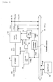
Figure 2 is an explanatory drawing for showing the operation of
power supply according to this embodiment. In this embodiment,
a pulse generation circuit is added to the mini PCI card 60 to
allow for power-on and boot operations for the ACPI-conformable
PC power supply in response to the power supply from the AC
adapter 51 without operator intervention. The WAKE-ON-LAN
function to turn on the PC in response to the instructions
through a network is divided into a first aspect wherein the PC
starts up from its power-off state and a second aspect wherein
the PC automatically wakes up from its sleep state. In this
embodiment, the first aspect corresponds to the power-on
operation through the gate array logic 42 and the second aspect
corresponds to the return from its low power state through the
embedded controller 41 and the I/O bridge 21.
The AC adapter 51 shown in Figure 2 receives a supplied voltage
of 100 to 240 V AC and converts it to a voltage of 16 V DC.
The DC/DC converter 55 receives the DC voltage of 16 V and
generates DC constant voltages: Vcc1 of 12 V, 2.5 V, 1.5 V, or
5 V, Vcc2 of 3.3 V, and VccAUX of 3.3 V which is an auxiliary
power. The auxiliary power VccAUX is supplied to the PCI bus
20 to allow for automatic power-on when the PC body comprising
the computer system 10 is supplied with power from the AC
adapter 51. It should be appreciated that at the stage when
the power supply is connected via the AC adapter 51, only the
auxiliary power VccAUX is provided by the DC/DC converter 55 to
portions other than those for power control and that the
voltages Vcc1 and Vcc2 are made available when the power switch
goes into its ON state.
The auxiliary power VccAUX supplied to the PCI bus 20 through
the connected AC adapter 51 is supplied to the mini PCI card 60
connected to the PCI bus 20. The mini PCI card 60 according to
this embodiment has an automatic power-on circuit therein. The
automatic power-on circuit is configured to be triggered by the
auxiliary power VccAUX to provide a negative pulse with a
predetermined delay after its rising and is also configured to
connect its output to a signal line for the PCI bus 20 called
- PME (Power Management Event).
The negative pulse -PME generated by the automatic power-on
circuit is supplied to the gate array logic 42 provided in the
core chip of the I/O bridge 21. The output of the gate array
logic 42 is connected to one input of an OR circuit 81. A
power switch is connected to the other input of the OR circuit
81 and either of these inputs allows a POWER ON signal to be
supplied to the DC/DC converter 55, turning on the computer
system 10. According to this embodiment, the same functions as
those performed when the power switch is pressed down can be
activated by detecting the -PME pulse through the gate array
logic 42. Furthermore, according to this embodiment, the
power-on and boot operations can be performed irrespective of
the operation of the power switch by mounting the mini PCI card
60 on a PC which supports the WAKE-ON-LAN function.
On the other hand, the wake-up from a low power state which is
otherwise performed by the OS is performed by the embedded
controller 41 in this embodiment. More specifically, when the
embedded controller 41 receives the negative pulse -PME in a
sleep or soft-off state, it issues a wake-up instruction to the
DC/DC converter 55 via the I/O bridge 21. This can allow the
PC to return from its low power state to a previous state.
Next, the automatic power-on circuit according to this
embodiment will be described below with reference to Figures 3
and 4.
Figure 3 is a circuit diagram for showing an example of the
automatic power-on circuit according to this embodiment.
Figure 4 shows waveforms obtained at the points (1) to (7) in
Figure 3 with the horizontal axis indicating time and the
vertical axis indicating voltage. It should be appreciated
that the circuit diagram and waveforms in the drawings show
only an example of this embodiment and other circuits may be
used to implement the present invention.
As shown in Figure 3, the voltage obtained from the auxiliary
power VccAUX rises not rapidly but slowly due to a noise
reducing section which is constituted by, for example, a
resistor of 100 kΩ(R1) 62, a capacitor of 2.2 µF (C1) 63, and a
diode 64 (D1). As a result, at the point (1), the voltage
rises very gently as shown in Figure 4(1). For example, an
intermittent electric current with "crackling" may be caused
when the user inserts a connector into an AC convenience
receptacle but such a phenomenon can be cancelled by using this
noise reducing section to dull the voltage waveform.
Then, the dulled voltage is supplied to an inverter 65 which is
an inverting circuit. The inverter 65 determines the input to
be 1 which is above a certain threshold level or to be 0 which
is below the level for binarization and produces an inverted
output. Thus, a waveform as shown in Figure 4(2) is obtained
at the point (2). As shown in Figure 4(2), the output voltage
changes from 1 to 0 when it exceeds a certain level.
The output from the inverter 65 is supplied to one input
terminal of an XOR (exclusive OR) circuit 69. The output from
the inverter 65 is also dulled into a gentle waveform by, for
example, a resistor of 100 kΩ(R2) 66 and a capacitor of 0.82 µF
(C2) 67 and an output waveform as shown in Figure 4(3) is
obtained at the point (3). This output is then supplied to an
inverter 68 where it is binarized and inverted to produce at
the point (4) a phase-inverted output as shown in Figure 4(4),
which is shifted in time from the waveform (2) by t (for
example, 80 ms). Namely, the resistor (R2) 66, the capacitor
(C2) 67, and the inverter 68 constitute the function of
generating a predetermined delayed waveform and the function of
inverting it. A larger time constant provided by the resistor
(R2) 66 and the capacitor (C2) 67 can produce a longer delay
time and then, the delayed and inverted output is supplied to
the other input terminal of the XOR circuit 69. It should be
appreciated that the -PME signal is assumed herein to have a
pulse width of "at least 50 ms" and the time t is approximately
80 ms in this embodiment.
The XOR circuit 69 performs the exclusive OR operation and
produces an output of 1 when the two inputs (2) and (4) do not
match. More specifically, since the two inputs have the same
value in their portions corresponding to the delay time t as
shown in the waveform of Figure 4(4) but they have different
values in other portions, a waveform as shown in Figure 4(5) is
obtained at the point (5) in Figure 3. Namely, if any delay
occurs, a duration of "0" will be formed.
The output from the XOR circuit 69 is inverted by the inverter
70 and then supplied to a transistor 72 through a resistor of
2.2 kΩ(R3) 71. In the PCI standard, the PME signal can be
activated by other circuits for controlling the power
management. Therefore, an open collector (open state) allows
the collector of the transistor 72 to be used as an output,
which will not be affected by other circuits being pulled down
to low. It should be appreciated, however, that the inverter
70 is provided between the XOR circuit 69 and the transistor 72
because the output of the transistor 72 is inverted. More
specifically, an inverted waveform as shown in Figure 4(6) is
obtained at the point (6) which corresponds to the output of
the inverter 70 and an electric current having a pulse waveform
as shown in Figure 4(7) is supplied to the PME terminal at the
point (7) which corresponds to the output of the transistor 72.
It should be appreciated that the -PME signal is used for this
embodiment since the signal line also serves as a wake-up
signal for the WAKE-ON-LAN function. As described above, the
PME wake-up operation described in the PCI standard wakes up a
CPU, a hard disk, a display, or any other device in its low
power state which is operationally equivalent to suspension.
However, the WAKE-ON-LAN in this embodiment refers to turning a
system from its OFF state into its ON state and the length
requirement for PME signals specified in "PCI Bus Power
Management Interface Specification" Rev1.1 does not apply to
it. For example, the pulse width of a -PME signal may be
defined to be "at least 50 ms" as described above.
Thus, this embodiment requires no change to the PC body because
a circuit for driving the -PME signal to active is implemented
on the mini PCI card 60. A card which supports the WAKE-ON-LAN
function has a similar circuit on the mini PCI card 60 but it
cannot allow the PC to turn on by itself because it performs
its own function when a magic packet is sent from outside
through a network. This embodiment provides a circuit which
can unconditionally drive the -PME signal to active when the
auxiliary power VccAUX is supplied by the DC/DC converter 55,
for example, through the connection of the AC adapter 51, in
synchronization with the power supply. This can allow for
automatic power-on (outputs Vcc1 and Vcc2) without intervention
from outside.
Another embodiment can be configured by using other ICs (for
example, reset ICs) capable of generating such a pulse, rather
than the circuit shown in Figure 3. Other alternative
embodiments can be accomplished by selecting an optional
configuration such as that for providing digital outputs by
means of a counter. It should be appreciated that the circuit
shown in Figure 3 is more advantageous in that the system can
be configured at a very low cost.
This embodiment in which the AC adapter 51 is provided has been
described above but still another embodiment may be configured,
for example, by providing the PC body with a power cable to be
connected to commercial power and by providing an AC/DC
converter in the PC body rather than the AC adapter 51. In
addition, this embodiment is configured to supply the auxiliary
power VccAUX but it is unimportant whether the AC adapter 51 is
provided, if some power is supplied to the circuits connected
to the bus when the system is connected to a power supply.
Giving a summary of the operations in this embodiment, when
some power is supplied to the PC body in a mechanical off
state, for example, by connecting the AC adapter 51 to a
commercial power receptacle, the auxiliary power VccAUX is
supplied to the mini PCI card 60 to support the WAKE-ON-LAN
function. In the meantime, the mini PCI card 60 is provided
with a circuit for generating a negative pulse with a certain
delay after the start-up of the power so that any output
produced by the supplied auxiliary power VccAUX is connected to
the -PME pulse in the PCI bus 20. Thus, the PC body can be
waken up from the mechanical off state by managing the -PME
pulse.
According to this embodiment, the PC which supports the
WAKE-ON-LAN function can turn on and boot up irrespective of
the power switch, by providing the PC with the mini PCI card 60
of the configuration described above without any change to the
PC body. Consequently, even a PC which goes into a soft-off
state due to the ACPI-conformable "POWER BUTTON OVER-RIDE"
function, can turn on without any operation of the power switch
and thus this can avoid the problem of going into soft-off
state. In addition, the maintenance for the PC can be
accomplished only by providing a spare mini PCI card 60 because
no change is made to the PC body. Furthermore, if the PC in
use is to be replaced with a new model PC due to phase out or
other reasons, the same functions can be performed by moving
the mini PCI card 60 into the new model PC. If any change was
made to the PC body to perform the same functions, additional
changes would be required each time the PC is replaced with a
new one. Thus, the present invention would provide much more
advantages and cost reduction effects.
As described above, according to the present invention, a PC
can be turned on for start-up through power supply from an
external power supply, irrespective of the power switch.