Field of the Invention and
Related Art Statement
-
The present invention relates to an image forming apparatus
using an electrophotographic system, such as a copying machine,
a printer, a facsimile, or a combination machine of the
above-mentioned machines, and more specifically to an image forming
apparatus in which a special image can be obtained in addition to
a normal toner image.
-
Conventionally, an image forming apparatus such as a copying
machine or a printer that utilizes the electrophotographic system
or the electrostatic transfer system is widely known. In such an
image forming apparatus, a black-and-white image, a full-color image
formed with toners of yellow, cyan, and magenta, and the like are
usually formed on a paper and outputted. In addition, unlike the
technique for obtaining these (flat) images, there has been proposed
a technique for obtaining a three-dimensional image using a special
toner (foaming toner). For example, the applicant has already
proposed "Image forming toner, preparation method thereof,
three-dimensional image forming method and image forming apparatus"
and "Image forming apparatus" in JP 2000-131875 A and JP 2001-194846
A, respectively. Further, there has been conventionally proposed
a technique for obtaining an image in gold, silver, etc. using a
special toner (toner of a metallic color).
-
However, it is inappropriate that all the image forming
apparatuses are previously constructed to be capable of forming
an image by using a special toner (foaming toner or toner of a metallic
color). This is because a user who does not need an image formed
of the special toner is compelled to unnecessary functions and costs .
On the other hand, it is inefficient to manufacture completely
separately an image forming apparatus using only a normal toner
and an image forming apparatus using the special toner as well as
the normal toner. Therefore, it is conceivable that an optional
developing device using a special toner is mounted to the image
forming apparatus using only a normal toner, so that an image forming
apparatus to meet the users' needs is efficiently provided.
-
Note that, as for the special toner, it is required in its
nature to specify the order that toners are superposed on the paper.
The reason for this is as follows. That is, for example, if a toner
layer including a foaming-toner layer is laminated on a paper, by
arranging the foaming-toner layer on the lower side than a
normal-toner layer (first developer) mainly used for coloring, a
colored layer including the first developer can be lifted by the
foaming-toner layer from underneath, so that a three-dimensional
image can be obtained. Also, it is difficult to inhibit appropriate
color reproduction (formation) due to a color mixture among the
first developers, so that an objective optimal image can be obtained.
If the foaming-toner layer is formed in the upper layer or the
intermediate layer of the first developer, particularly color
reproducibility deteriorates. Further, in the case of laminating
a toner layer including a metallic-toner layer on a paper, when
the metallic-toner layer is not mixed with other colors, a gloss
with more metallic sensation can be obtained. Accordingly, the color
mixture can be avoided as much as possible by forming the
metallic-toner layer in the uppermost layer with respect to other
toner layers, so that an objective optimal image can be obtained.
Object and Summary of the Invention
-
Therefore, the present invention has been made in view of the
above circumstances and provides an image forming apparatus in which,
if the image forming apparatus using only a normal toner is modified
to be capable of forming an image formed of a special toner, an
appropriate image can be formed in accordance with characteristics
of the special toner.
-
According to the present invention, there is provided an image
forming apparatus including: an image bearing member; a first
developing unit for forming an image consisting of one kind or plural
kinds of first developer on the image bearing member; a transfer
section for transferring the image formed on the image bearing member
onto a recording medium, the image forming apparatus being capable
of mounting thereto a second developing unit for forming an image
consisting of one kind or plural kinds of second developer different
from the first developer on the image bearing member; a developing
unit judging section for judging a kind of a developing unit included
in the image forming apparatus; and a control unit for controlling
stacking of images on the recording medium based on a judgment result
of the developing unit judging section.
-
Here, the second developing unit may be (alternatively)
mountable so as to replace an entirety or a part of the first developing
unit, or may be (additionally) mountable so as to be added to the
first developing unit. Also, the developing unit may be mounted
to the image forming apparatus one by one, or the plural developing
units may be collectively mounted to the image forming apparatus.
Moreover, the developing unit may be mounted to the image forming
apparatus solely by itself, or an image forming unit including the
image bearing member as well as the developing unit may be mounted
to the image forming apparatus.
-
In addition, the first developer and the second developer can
be distinguished from each other in that the first developer does
not contain a foaming agent and the second developer contains a
foaming agent, the first developer contains a colorant of a
nonmetallic color and the second developer contains a colorant of
a metallic color, the first developer contains a colorant of a
chromatic color and the second developer contains a colorant of
an achromatic color, or the first developer contains a specific
colorant and the second developer contains a colorant different
from the specific colorant.
-
Examples of the first developer include a developer (of one
type) containing a colorant of black, developers of three types
containing colorants of yellow, magenta, and cyan, respectively,
and developers of four types containing a colorant of black in addition
to these developers of three types. In addition, as examples of
the second developer, there are a colorless developer (of one type)
containing a foaming agent and not containing a colorant, a developer
(of one type) containing a foaming agent and a colorant, a developer
(of one type) not containing a foaming agent and containing a colorant
of a metallic color, and developers of plural types that are arbitrary
combinations of the above-mentioned developers. Note that the
foaming agent and the colorant may be internally added or externally
added to a developer.
-
Further, under a first control performed by the control unit,
the image forming apparatus can be controlled such that, in the
case of using the second developing unit mounted thereto, an image
consisting of the second developer is formed into a specific-level
layer within a stack of images on the recording medium. Here, the
specific-level layer may be (1) automatically determined by the
image forming apparatus (without an operation by a user), or (2)
determined based on an instruction by a user.
-
In other words, in the case of the former (1), the specific-level
layer is automatically determined in accordance with the kind of
the second developing unit to be used. For example, if the first
developer contains no foaming agent and the second developer contains
a foaming agent, the specific-level layer is automatically
determined to be a lowermost layer in the stack of the images on
the recording medium. In another example, if the first developer
contains a colorant of a nonmetallic color and the second developer
contains a colorant of a metallic color, the specific-level layer
is automatically determined to be an uppermost layer in the stack
of the images on the recording medium.
-
Alternatively, in the case of the latter (2), a user interface
section to which an instruction from a user is inputted is provided
to the image forming apparatus, and the specific-level layer is
determined based on an instruction from the user interface section.
Examples of the user interface section include an operation button
and an operation panel of the image forming apparatus . In the similar
case where the specific-level layer is determined based on an
instruction from the user, the instruction from the user may be
transmitted to a printer (image forming apparatus) via a computer
(including a printer driver) connected thereto.
-
Examples of a method of controlling the stacking of the images
on the recording medium include: a method of controlling the stacking
of the images on the recording medium by controlling the order that
each developing unit forms an image on the image bearing member
by the control unit; and a method of controlling the stacking of
the images by controlling the order that the transfer section
transfers the images (onto the intermediate transfer member and
the recording medium) by the control unit.
-
Further, under a second control performed by the control unit,
the image forming apparatus can be controlled such that, in the
case of using the second developing unit mounted thereto, an image
consisting of the second developer is formed to be laminated on
the recording medium based on an electrophotographic parameter (one
or more parameters selected from the group consisting of, for example,
a developing bias, a charging bias (an image bearing member surface
potential), a transferring bias, a fixing temperature, a fixing
rate, and an image processing parameter) which differs from the
electrophotographic parameter used in the case where an image
consisting of the first developer is formed to be laminated on the
recording medium. Here, the electrophotographic process parameter
may be automatically determined by the kind of the second developing
unit to be used.
-
Further, in order to judge the kind of the developing unit
mounted to the image forming apparatus, the developing unit may
have a special shape in accordance with its developer, and may include
the developing unit judging section for judging the kind of the
mounted developing unit based on the special shape. Also, the
developing unit may include a nonvolatile memory for storing
developer information that indicates a developer of the developing
unit in the nonvolatile memory, and may include the developing unit
judging section for judging the kind of the mounted developing unit
based on the read developer information. Moreover, if the image
forming unit including the image bearing member as well as the
developing unit is mounted to the image forming apparatus, the image
forming unit may have the special shape in accordance with the
developer, or may include the non-volatile memory.
-
Also, the present invention relates to an image forming
apparatus including: an image bearing member; a first developing
unit for forming an image consisting of one kind or plural kinds
of first developer on the image bearing member; and a transfer section
for transferring the image formed on the image bearing member onto
a recording medium, the image forming apparatus being capable of
mounting thereto a second developing unit for forming an image
consisting of one kind or plural kinds of second developer on the
image bearing member.
-
Further, according to the present invention, there is also
provided an image forming apparatus which includes an image bearing
member, a first developing unit for forming an image consisting
of one kind or plural kinds of first developer on the image bearing
member, and a transfer section for transferring the image formed
on the image bearing member onto a recording medium, and to which
a second developing unit for forming an image consisting of one
kind or plural kinds of second developer on the image bearing member
is mountable, the image forming apparatus including: a user interface
section to which an instruction from a user is inputted; and a control
unit for controlling the image forming apparatus such that, in the
case of using the second developing unit mounted thereto, an image
consisting of the second developer is formed into a specific-level
layer within a stack of images on the recording medium, the
specific-level layer being determined based on the instruction from
the user interface section.
-
In addition, the transfer unit may include only a final transfer
section and transfer an image on the image bearing member to a
recording medium directly. Alternatively, the transfer unit may
be provided with an intermediate transfer member and an intermediate
transfer section in addition to the final transfer section, transfer
an image on the image bearing member to the intermediate transfer
member once by the intermediate transfer section, and further
transfer the image on the intermediate transfer member to a recording
medium by the final transfer section.
-
Further, the present invention can be applied to any image
forming apparatus of the electrophotographic system. Turning to
a relationship between a developing unit and an image bearing member
(photosensitive member, latent image bearing member), there are
an image forming apparatus in which each developing unit and image
bearing member has a one to one relationship and an image forming
apparatus in which each developing unit and image bearing member
has an N (N is a natural number) to one relationship. As examples
of the former image forming apparatus, there are a monochrome image
forming apparatus, a full-color image forming apparatus of the tandem
system using an intermediate transfer member, from an upstream side
to a downstream side of which image forming units corresponding
to each color are arranged, and the like. As examples of the latter
image forming apparatus, there are image forming apparatus using
a developing apparatus of the rotary system, a full-color image
forming apparatus in which developing units corresponding to each
color are arranged from an upstream side to a downstream side of
an image bearing member, and the like.
As described above, according to the present invention, if
the image forming apparatus using only a normal toner is modified
to be capable of forming an image formed of a special toner, there
can be provided an image forming apparatus capable of forming an
appropriate image in accordance with the characteristics of the
special toner.
Brief Description of the Drawings
-
Preferred embodiments of the present invention will be
described in detail based on the following drawings, wherein:
- Fig. 1 is a cross-sectional schematic view for explaining an
example of a color printer according to Embodiment Modes 1 to 3
of the present invention;
- Fig. 2 is a cross-sectional schematic view for explaining an
example of a color copying machine according to Embodiment Modes
1 to 3 of the present invention;
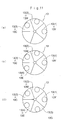
- Figs. 3A and 3B are cross-sectional schematic views for
explaining a rotary developing apparatus of the color printer or
the color copying machine according to Embodiment Mode 1 of the
present invention;
- Fig. 4 is a perspective view for explaining how a developing
device is removed from the rotary developing apparatus of Figs.
3A and 3B;
- Figs. 5A to 5C are cross-sectional views for explaining
projected portions and buttons of a developing device of the rotary
developing apparatus of Figs. 3A and 3B;
- Fig. 6 is ablock diagram for explaining a structure of a control
system of the color printer or the color copying machine according
to Embodiment Modes 1 to 3 of the present invention;
- Fig. 7 is a flow chart for explaining an operation of a control
system of the color printer or the color copying machine according
to Embodiment Modes 1 to 3 of the present invention;
- Figs. 8A1 to 8A4, 8B1 to 8B4, and 8C are used for explaining
steps and states of stacking toner images on a photosensitive drum,
an intermediate transfer belt, and a recording paper;
- Figs. 9A to 9C are used for explaining an image processing
control of the color printer according to Embodiment Modes 1 to
5 of the present invention;
- Figs. 10A and 10B are cross-sectional schematic views for
explaining a rotary developing apparatus of the color printer or
the color copying machine according to Embodiment Mode 2 of the
present invention;
- Figs. 11A and 11B are cross-sectional schematic views for
explaining a rotary developing apparatus of the color printer or
the color copying machine according to Embodiment Mode 3 of the
present invention;
- Figs. 12A1 to 12A3, 12B1 to 12B3, and 12C are used for explaining
steps and states of stacking toner images on a photosensitive drum,
an intermediate transfer belt, and a recording paper;
- Figs. 13A1 to 13A5, 13B1 to 13B5, and 13C are used for explaining
steps and states of stacking toner images on a photosensitive drum,
an intermediate transfer belt, and a recording paper;
- Fig. 14 is a cross-sectional schematic view showing a main
part of the color printer or the color copying machine according
to Embodiment Modes 4 and 5 of the present invention;
- Figs. 15A and 15B are used for explaining an image forming
section of Fig. 14; and
- Fig. 16 is a block diagram for explaining a control system
of the color printer according to Embodiment Modes 4 and 5 of the
present invention.
-
Detailed Description of the Preferred Embodiments
-
Embodiment Modes of the present invention will be hereinafter
described with reference to the accompanying drawings properly.
Embodiment Mode 1
-
Fig. 1 shows a color printer 100 of the electrophotographic
system as an image forming apparatus according to Embodiment Mode
1 of the present invention. In addition, Fig. 2 shows a color copying
machine 102 of the electrophotographic system as the image forming
apparatus according to Embodiment Mode 1 of the present invention.
-
In Figs. 1 and 2, reference numeral 100 denotes a color printer
and a main body of a color copying machine. As shown in Fig. 2,
an original reader 101 for reading an image of an original d pressed
by a platen cover 61 is arranged above this color copying machine
main body 100. This original reader 101 is adapted to illuminate
the original d placed on a platen glass 62 with light sources 63a
and 63b, scan and expose a reflected light image from the original
d on an image reading element 60 including CCD via a reduction optical
system including a full-rate mirror 64, half-rate mirrors 65 and
66, and a focusing lens 67, and read a light image reflected by
coloring material of the original d with this image reading element
60 at a predetermined dot density (e.g., 16 dots/mm).
-
The light image reflected by coloring material of the original
d read by the original reader 101 is sent to an image processing
apparatus 30 as, for example, reflectance data of original for three
colors of red (R), green (G), and blue (B) (8 bits each). In this
image processing apparatus 30, predetermined image processing such
as shading correction, positional deviation correction,
brightness/color spatial conversion, gamma correction, frame
deletion, or color/movement edition is applied to the reflectance
ratio data of the original d.
-
Then, the image data subjected to the predetermined image
processing in the image processing apparatus 30 as described above
is sent to a raster output scanner (ROS) 12 as gradation data of
original coloring material for four colors of yellow (Y), magenta
(M), cyan (c), and black (BK) (8 bits each) . In this ROS 12, image
exposure by laser beams is performed according to the gradation
data of original coloring material.
-
An image forming section capable of forming plural toner images
of different colors is disposed inside the color printer 100 and
the copying machine main body 100. This image forming section is
constituted mainly of the ROS 12 as an image exposure section, a
photosensitive drum 10 as an image bearing member on which an
electrostatic latent image is formed, and a developing apparatus
13 of the rotary system as a developing section capable of developing
the electrostatic latent image formed on the photosensitive drum
10 to form plural toner images of different colors.
-
As shown in Figs. 1 and 2, the ROS 12 modulates a not-shown
semiconductor laser according to gradation data of original
reproducing coloring material and emits a laser beam LB from this
semiconductor laser according to the gradation data. The laser beam
LB emitted from this semiconductor laser is deflected and scanned
by a not-shown rotary polygon mirror, and scanned and exposed on
the photosensitive drum 10 as an image bearing member via a not-shown
f· lens and reflection mirror.
-
The photosensitive drum 10 on which the laser beam LB is scanned
and exposed by the ROS 12 is adapted to be rotated and driven at
a predetermined speed along an arrow direction by a not-shown drive
section. The surface of this photosensitive drum 10 is charged to
a predetermined polarity (e.g., negative polarity) and potential
by a Scorotron 11 for primary charging in advance and, then, an
electrostatic latent image is formed as the laser beam LB is scanned
and exposed according to the gradation data of original reproducing
coloring material. For example, the surface of the photosensitive
drum 10 is uniformly charged to -650 V and, then, the laser beam
LB is scanned and exposed on an image portion thereof, and an
electrostatic latent image with -200 V in the exposed part is formed
thereon.
-
The electrostatic latent image formed on the photosensitive
drum 10 is subjected to reversal development, for example, with
a toner (charged coloring material) charged in the negative polarity,
which is the same polarity as the charged polarity of the
photosensitive drum 10, in a development region D by the developing
apparatus 13 of the rotary system provided with developing devices
(first developing units) 13Y to 13BK corresponding to yellow (Y),
magenta (M), cyan (C) , and black (BK), and turns into a toner image
T of a predetermined color. In this case, for example, a developing
bias voltage of -500 V is applied to developing rolls of the developing
devices 13Y to 13BK. Note that the toner image formed on the
photosensitive drum 10 is subjected to charging of a negative polarity
by a pre-transfer charger 14 if necessary, and an amount of charges
of the toner image is adjusted.
-
A toner image (image) of a toner (first developer) of each
color formed on the photosensitive drum 10 is multiply transferred
onto an intermediate transfer belt 20 serving as an intermediate
transfer member, which is arranged below the photosensitive drum
10, at a first nip portion T1 by a primary transfer roll 15 serving
as a first transfer section. This intermediate transfer belt 20
is stretched and suspended by a drive roll 21, a driven roll 26,
a tension roll 22, and a backup roll 23 serving as an opposed roll
forming a part of a secondary transfer section, and supported
rotatably along an arrow direction at a moving speed identical with
a peripheral speed of the photosensitive drum 10.
-
Toner images of all or a part of four colors of yellow (Y),
magenta (M), cyan (C), and black (BK) formed on the photosensitive
drum 10 are sequentially transferred in a stacked state onto the
intermediate transfer belt 20 by the primary transfer roll 15
according to a color of an image to be formed. The toner image
transferred onto the intermediate transfer belt 20 is transferred
onto a recording paper P, which serves as a recording medium to
be conveyed to a secondary transfer position T2 at predetermined
timing, by a press-contacting force and an electrostatic attracting
force acting between the backup roll 23 supporting the intermediate
transfer belt 20 and a secondary transfer roll 24 forming a part
of the secondary transfer section that is in press-contact with
the backup roll 23.
-
As shown in Figs. 1 and 2, the recording paper (recording medium)
P of a predetermined size supported by a sheet guide 41 is fed from
a sheet feeding cassette 40, which serves as a recording medium
containing member arranged in the lower part of the color printer
100 and the copying machine main body 100, by the pickup roll 42
and feed and retard rolls 43. The fed recording paper P is conveyed
to a secondary transfer position T2 of the intermediate transfer
belt 20 at predetermined timing by plural conveyor rolls 44 and
registration rolls 45. Then, as described above, toner images of
predetermined colors are collectively transferred on to the recording
paper P from the intermediate transfer belt 20 by the backup roll
23 and the secondary transfer roll 24 serving as the secondary transfer
section.
-
In addition, after being separated from the intermediate
transfer belt 20, the recording paper P, to which the toner images
of predetermined colors are transferred from the intermediate
transfer belt 20, is conveyed to a fixing apparatus 50. Then, the
toner images are fixed on the recording paper P with heat and pressure
by a heating roll 51 and a pressure roll 52 of the fixing apparatus
50, and discharged to the outside of the color printer 100 and the
copying machine main body 100, whereby the process of forming a
color image ends.
-
Note that, in Figs. 1 and 2, reference numeral 16 denotes a
cleaning device for removing a residual toner, paper powder, and
the like from the surface of the photosensitive drum 10 after the
transfer process ends; 27, a cleaner for intermediate transfer belt
for cleaning the intermediate transfer belt 20; and 25, a cleaner
for cleaning the secondary transfer roll 24. In addition, the cleaner
for intermediate transfer belt 27 and the cleaner 25 for the secondary
transfer roll 24 are constituted so as to come into contact with
and separate from the intermediate transfer belt 20 at predetermined
timing.
-
Incidentally, in the color printer 100 and the color copying
machine 102 according to Embodiment Mode 1, it is possible to mount
a developing device (secondary developing unit) 13E corresponding
to a foamable toner E (second developer containing a foaming agent
and not containing a colorant) in place of one of the developing
devices ( first developing units) 13Y to 13BK corresponding to toners
(first developers not containing a foaming agent and containing
a colorant of a nonmetallic color) of yellow (Y), cyan (C), magenta
(M), and black (BK), respectively. Note that, when heated by the
fixing apparatus 50, the foamable toner E discussed later is expanded
by the heat and can form a three-dimensional image on the recording
paper P.
-
As shown in Figs. 3A and 3B, the developing apparatus 13 of
the rotary system is provided with first to fourth developing devices
13(1) to 13(4) different from each other for each of its four areas
divided equally in a fan shape around its rotation axis . In addition,
as shown in Fig. 4, each of the developing devices 13(1) to 13(4)
slides along a guide rail provided in each of the developing devices
13(1) to 13(4), which is parallel with the rotation axis, and a
guide rail support provided in the developing apparatus main body
to be opposed to the guide rail by applying a force in a direction
B and a direction A in the figure, and is constituted detachably.
-
In this way, in the color printer 100 and the color copying
machine 102 using only the normal toners of yellow (Y), cyan (C),
magenta (M), and black (BK), it becomes also possible to form an
image with the special foamable toner E simply by replacing developing
devices.
-
In addition, as shown in Figs . 5A to 5C, in a developing apparatus
main body 13, a first button (developing unit judging section) 13a
and a second button (developing unit judging section) 13b are provided.
In each of the developing devices 13(1) to 13(4), a projected portion
(special shape) 130 of a shape corresponding to characteristics
of a developer contained in the developer is provided. The developing
apparatus main body 13 is constituted such that, when each of the
developing devices (1) to (4) is mounted on the developing apparatus
13, these first and second buttons 13a and 13b and the projected
portion 130 are opposed to each other.
-
Here, in each of the developing devices 13Y to 13BK
corresponding to the toners of yellow (Y), cyan (C), magenta (M),
and black (BK), first projected portions 130Y to 130BK are formed
as shown in Fig. 5A. When the developing devices 13Y and 13BK are
mounted on the developing apparatus main body 13, only the first
button 13a is pressed. In addition, in the developing device 13E
corresponding to the foamable toner E, a second projected portion
130E as shown in Fig. 5B is formed. When the developing device 13E
is mounted on the developing apparatus main body 13, only the second
button 13b is pressed. Note that, in a developing device 13G
corresponding to a gold toner G in Embodiment Mode 2 discussed later,
a third projected portion 130G as shown in Fig. 5C is formed. When
the developing device 13G is mounted on the developing apparatus
13, both the first button 13a and the second button 13b are pressed.
Note that, although the developing devices of three types (the
developing devices Y to BK, the developing device E, and the developing
device G) are explained as being distinguished for simplicity, the
developing devices Y to BK can be distinguished, respectively, by
increasing the number of combinations of buttons and projected
portions.
-
Moreover, when a developing device of the color printer 100
and the color copying machine 102 according to Embodiment Mode 1
is replaced, update of <1> an order of image formation, <2> image
processing parameters, and <3> electrophotographic process
parameters is automatically controlled according to characteristics
of a toner contained in the replaced developing device. In this
way, the image forming apparatus according to Embodiment Mode 1
makes it possible not only to form an image with the special foamable
toner E by replacing a developing device but also to form an
appropriate image according to characteristics of the foamable toner
E.
-
Fig. 6 is a functional block diagram illustrating a structure
of this update control system. This control system is constituted
with a control unit 70 as a main part. Signals inputted in the control
unit 70 are <1> ON/OFF signals from the first button 13a and the
second button 13b and <2> an instruction signal from a user interface
device (user interface section) 80 including a touch panel or an
operation button of the color printer 100 or a color copying machine
102. Signals outputted to the control unit 70 are <1> a drive command
given to a developing motor 13m for rotating the developing apparatus
13 of the rotary system, <2> an image processing update command
for updating image processing parameters in the image processing
apparatus 30, and <3> a process update command for updating
electrophotographic process parameters in each functional
components of an image forming apparatus.
-
Moreover, this process update command of <3> includes a
charging bias update command given to a charging power supply section
11p for applying a charging bias to the Scorotron 11, a developing
bias update command given to a developing power supply section 13p
for applying a developing bias to each of the developing devices
13(1) to 13(4) of the developing apparatus 13, a primary bias update
command given to a primary transfer power supply section 15p for
applying a primary transfer bias to the primary transfer roll 15,
a drive command given to a fixing motor 50m for rotating the heating
roll 51 and the pressure roll 52, and a heating power update command
given to a heating power supply section 51p for applying an electric
power to a halogen lamp (heating source) of the heating roll 51.
The control unit 70 can control a charging potential, a developing
bias, a primary transfer bias, a secondary transfer bias, a fixing
rate, and a fixing temperature on the photosensitive drum 10 according
to these process update commands, respectively.
-
Note that, as a specific structure of the control unit 70,
the control unit 70 is provided with a hardware configuration
including a central processing unit, a control device, a memory
device, an input/output device, a bus connecting these devices each
other, and the like, and a software configuration including a control
program and the like stored in the memory device in advance.
Functions of the control unit 70 are realized by the hardware
configuration and the software configuration.
-
Fig. 7 is a flow chart explaining operations of this update
control system. Update control operations of the color printer 100
and the color copying machine 102 according to Embodiment Mode 1
will be hereinafter described in accordance with this flow chart.
Embodiment 1
-
In explaining the update control operations of the color
printer 100 and the color copying machine 102 according to Embodiment
Model, as an example (Embodiment 1) thereof, a case will be described
in which the image forming apparatus is mounted with the developing
device 13BK corresponding to the black toner BK as the first developing
device 13(1), the developing device 13Y corresponding to the yellow
toner Y as the second developing device 13(2), the developing device
13M corresponding to the magenta toner M as the third developing
device 13(3), and the developing device 13C corresponding to the
cyan toner C as the fourth developing device 13(4) as shown in Fig.
3A in an initial state of development and, thereafter, the first
developing device 13(1) is changed from the developing device 13BK
corresponding to the black toner BK to the developing device 13E
corresponding to the foamable toner E as shown in Fig. 3B.
-
Note that, hereinafter, a description will be made of a case
where the developing device 13BK corresponding to the black toner
BK is replaced with the developing device 13E corresponding to the
foamable toner E. However, the present invention is not limited
thereto and it is possible to appropriately select a developing
device for the replacement depending upon the image to be obtained.
Therefore, it is possible to replace a developing device
corresponding to another toner. For example, the developing device
13Y corresponding to the yellow toner Y is replaced with the developing
device 13E corresponding to the foamable toner E.
-
Figs. 8A1 to 8A4, 8B1 to 8B4, and 8C illustrate steps of forming
and stacking toner images in the color printer 100 and the color
copying machine 102 according to Embodiment Mode 1. Figs. 8A1 to
8A4 illustrate steps of forming toner images D1 to D4 on the
photosensitive drum 10 . Figs . 8B1 to 8B4 illustrate steps of forming
and stacking the toner images D1 to D4 on the intermediate transfer
belt 20. Fig. 8C illustrates a step of stacking the toner images
D1 to D4 on the recording paper P.
-
In this embodiment, the toner image (D1) formed of the black
toner BK, the toner image (D2) formed of the yellow toner Y, the
toner image (D3) formed of the magenta toner M, and the toner image
(D4) formed of the cyan toner C are developed on the photosensitive
drum 10 sequentially in the development region D, respectively,
in the initial state (see Figs. 1 and 2). These toner images are
primarily transferred onto the intermediate transfer belt 20
sequentially in the primary transfer position T1. Finally, the toner
image (D1) formed of the black toner BK, the toner image (D2) formed
of the yellow toner Y, the toner image (D3) formed of the magenta
toner M, and the toner image (D4) formed of the cyan toner C are
stacked from a bottom layer to a top layer on the intermediate transfer
belt 20. The stacked toner images are secondarily transferred onto
the recording paper P in the secondary transfer position T2 at one
time. As a result, the toner image (D4) formed of the cyan toner
C, the toner image (D3) formed of the magenta toner M, the toner
image (D2) formed of the yellow toner Y, and the toner image (D1)
formed of the black toner BK are stacked from a bottom layer to
a top layer on the recording paper P.
-
Next, after changing the first developing device 13(1) from
the developing device 13BK to the developing device 13E, when an
image is formed, the update control operation shown in the flow
chart of Fig. 7 is performed.
-
First, the control unit 70 judges whether or not the developing
device (second developing unit) 13E is mounted on the developing
apparatus 13 (S1 in Fig. 7). That is, in the case where the first
button 13a is "OFF" and the second button 13b is "ON", when the
developing device 13E is mounted, the control unit 70 judges that
the developing device 13E is mounted (see Fig. 5B).
-
In the case where the developing device 13E is mounted, the
control unit 70 judges whether or not the developing device (second
developing unit) 13E is used (S2 in Fig. 7). In the case of the
color printer 100, judgement is made based on whether or not a
three-dimensional image forming command is included in an image
forming command from a personal computer or the like connected to
the color printer 100. Alternatively, in the case of the color
copying machine 102, judgment is made based on whether or not a
three-dimensional image forming command has been inputted directly
from a user via the user interface device 102.
-
If the developing device 13E is used, the control unit 70 updates
an order of image formation of the image forming apparatus (S3 in
Fig. 7). That is, the control unit 70 sends a drive command to the
developing motor 13m, thereby updating the order of image formation
as follows: before replacing a developing device, the control unit
70 moves the developing devices 13(1) to 13(4) to the development
region D opposed to the photosensitive drum 10 in the order of the
first developing device 13(1) (= 13BK), the second developing device
13(2) (= 13Y), the third developing device 13(3) (= 13M), and the
fourth developing device 13(4) (= 13C) to develop images by the
developing devices 13(1) to 13(4), whereas, after replacing the
developing device, the control unit 70 moves the developing devices
13(1) to 13(4) to the development region D opposed to the
photosensitive drum 10 in the order of the second developing device
13(2) (= 13Y), the third developing device 13(3) (= 13M), the fourth
developing device 13(4) (= 13C), and the first developing device
13(1) (= 13E) to develop images by the developing devices 13(1)
to 13(4).
-
By updating an order of image formation as described above,
after replacing the developing device, the toner image (D1) formed
of the yellow toner Y, the toner image (D2) formed of the magenta
toner M, the toner image (D3) formed of the cyan toner C, and the
toner image (D4) formed of the foamable toner E are developed on
the photosensitive drum 10 sequentially in the development region
D, respectively, (see Figs. 1 and 2). These toner images are
primarily transferred onto the intermediate transfer belt 20
sequentially in the primary transfer position T1. Finally, thetoner
image (D1) formed of the yellow toner Y, the toner image (D2) formed
of the magenta toner M, the toner image (D3) formed of the cyan
toner C, and the toner image (D4) formed of the foamable toner E
are laminated from a bottom layer to a top layer on the intermediate
transfer belt 20. The laminated toner images are secondarily
transferred onto the recording paper P in the secondary transfer
position T2 at one time. As a result, the toner image (D4) formed
of the foamable toner E, the toner image (D3) formed of the cyan
toner C, the toner image (D2) formed of the magenta toner M, and
the toner image (D1) formed of the yellow toner Y, are laminated
from a bottom layer to a top layer on the recording paper P. That
is, the toner image (D4) formed of the foamable toner E always
constitutes the lowermost layer.
-
In addition, in the case where the developing device 13E is
used, the control unit 70 updates image processing parameters of
the image forming apparatus (S4 in Fig. 7). That is, the control
unit 70 sends an image processing update command to the image
processing apparatus 30, thereby first changing a type of gradation
data, and secondly performing image processing such that a toner
image formed of the other toners Y to C is not formed in the outline
part (over a very small width) of the toner image with the foamable
toner E.
-
Here, a type of gradation data is changed for the purpose of
performing image processing such that: gradation data of so-called
process black is obtained in which gradation data of yellow (Y),
magenta (M), and cyan (C) is used instead of obtaining gradation
data of single black (BK) and performing image processing, whereas,
before replacing the developing device, gradation data of four colors
of yellow (Y), magenta (M), cyan (C), and black (BK) (8 bits each)
is obtained from reflectance data of the original d; and gradation
data is newly generated for a three-dimensional image.
-
In addition, image processing as described below is performed
in order not to form a toner image formed of the other toners Y
to C in the outline part of the toner image formed of the foamable
toner E, or in order to form a toner image formed of the other toners
Y to C only on the upper surface of the toner image formed of the
foamable toner E and in order not to form a toner image formed of
the other toners Y to C on the side (slant surface) of the image
with the foamable toner E.
-
A toner image formed of the toners Y, M, and C, and the foamable
toner E, which is secondarily transferred onto the recording paper
P, is not formed in the same manner as a normal full-color image.
Image processing is performed such that a toner image formed of
the toners Y, M, and C is not formed over a predetermined very small
width (about several µm to 40 µm) in an outline part of a
three-dimensional image, which is formed with the foamable toner
E subsequent to forming the toner image formed of the toners Y,
M, and C, as shown in Fig. 9A. More specifically, the image processing
is adapted such that an edge part of a three-dimensional image is
detected by an edge detection circuit of the image processing
apparatus 30 and gradation data of Y, M, and C is not generated
over a predetermined very small width in the edge part of the
three-dimensional image. In this case, in the edge part of
three-dimensional image, a gap may be set over a predetermined very
small width in the external periphery of the three-dimensional image
as shown in Fig. 9B. Alternatively, a gap may be set over a
predetermined very small width in the internal periphery of the
three-dimensional image as shown in Fig. 9C.
-
By performing such image processing, a gap with a very small
width is formed in the outline part of the three-dimensional image
formed of the foamable toner E. Thus, even if a supporting body
such as the recording paper P is bent, an unbearable tension or
compressive force does not act on the toner image formed of the
toners Y, M, and C formed in the outline part of the three-dimensional
image, and the toner image formed of the toners Y, M, and C is not
destroyed. Therefore, it becomes possible to form a
three-dimensional full-color image having sufficient durability
at low costs.
-
In addition, in the case where the developing device 13E is
used, the control unit 70 updates electrophotographic process
parameters of the image forming apparatus (S5 in Fig. 7). That is,
the control unit 70 sends a charging bias update command, a developing
bias update command, a primary transfer bias update command, a
secondary transfer bias update command, a drive command, and a heating
power update command to the charging power supply section lip, the
developing power supply section 13p, the primary transfer power
supply section 15p, the secondary transfer power supply section
15p, the fixing motor 50m, and the heating power supply section
51p, respectively.
-
Thus, it is possible to control: a charging potential and a
developing bias on the photosensitive drum 10 when the developing
device 13E performs development; a primary transferring bias when
the toner image formed of the foaming toner E is primarily transferred;
a secondary transferring bias when the toner image with the foaming
toner E is secondary transferred; and a fixing rate and a fixing
temperature when the toner image with the foaming toner E is fixed.
At this time, the fixing temperature and the fixing rate can be
changed in accordance with the materials of the foaming toner E
and the normal toner, the image quality of the toner image to be
obtained, the height of the three-dimensional image after expansion,
and the like. Also, one or both of the fixing temperature and the
fixing rate can be changed. In this case, the fixing rate of only
the foaming toner E can be reduced to 20% to 95% of the fixing rate
of only the normal toner, and the fixing temperature of only the
foaming toner E can be increased to 5% to 40% of the fixing temperature
of only the normal toner.
-
After the above-mentioned image forming orders, image
processing parameters, and electrophotographic process parameters
have been automatically updated and determined, the control unit
70 performs image formation (S6 in Fig. 7). Here, the height of
the toner image consisting of this unfixed foamable toner E is 55
to 60 µm. Thereafter, fixing processing is performed with heat and
pressure by the heating roll 31 and the pressure roll 32 of fixing
device 30, so that the binder resin within the foamable toner E
is fused and the foaming agent within the formable toner E is foamed.
Thus, the three-dimensional image and the full-color image in Y,
M, and C are fixed onto the recording paper P. The three-dimensional
image fixed onto the recording paper P are expanded to have a height
of 130 µm. Note that, the fixing process is performed under the
condition that the fixing temperature is 150°C, the nip width between
the heating roll 51 and the pressure roll 52 is 4.8 mm, and the
fixing rate is 35 mm/sec.
-
Note that, although an order of development is automatically
determined according to a type of a mounted developing device in
Embodiment 1, the image forming apparatus can be constituted such
that a user can determine the order of development personally via
the user interface device (user interface section) 80.
-
Note that, although the case where the developing device 13BK
corresponding to the black toner BK forming the uppermost layer
(see D1 in Fig. 8) on the recording paper P is replaced with the
developing
device 13E corresponding to the foamable toner E, which
should form the lowermost layer (see D4 in Fig. 8) on the recording
paper P, is described in
Embodiment 1, other examples are shown
in
Embodiments 2 to 6 in Tables 1 and 2.
| | D1 | D2 | D3 | D4 |
| Embodiment |
| 1 | BK | Y | M | C |
| Embodiment |
| 2 | BK | Y | C | M |
| Embodiment |
| 3 | BK | M | Y | C |
| Embodiment |
| 4 | BK | M | C | Y |
| Embodiment |
| 5 | BK | C | Y | M |
| Embodiment 6 | BK | C | M | Y |
-
Table 1 shows combinations of the toner images D1 to D4 before
replacing a developing device. Table 2 shows combinations of the
toner images D1 to D4 after replacing the developing device . Moreover,
the developing device 13 corresponding to the toner forming the
layers other than the uppermost layer (see D2, D3, and D4 in Fig.
8) on the recording paper P can also be replaced with the developing
device 13E corresponding to the foamable toner E that should
constitute the lowermost layer (see D4 in Fig. 8) on the recording
paper P.
Embodiment Mode 2
-
In the color printer 100 and the color copying machine 102
according to Embodiment Mode 2, instead of one of the developing
devices (first developing units) 13Y to 13BK corresponding to the
toners (first developer including no foaming agent and including
a colorant of a nonmetallic color) in the respective colors of yellow
(Y), cyan (C), magenta (M), and black (BK) , developing device (second
developing unit) 13G corresponding to gold toner G (second developer
including no foaming agent and including a colorant of a metallic
color) can be mounted to the apparatus. Note that the structural
members identical to those of the color printer 100 and the color
copying machine 102 according to Embodiment Mode 1 are denoted by
the same symbols and a description thereof will be omitted.
-
As shown in Figs. 10A and 10B, this rotary developing apparatus
13 is provided with first to fourth developing devices 13(1) to
13(4) that are different from each other in each of regions that
are obtained by dividing the apparatus into four fan shapes about
the rotation axis. As shown in Fig. 4, the developing devices 13(1)
to 13(4) are structured to be detachably mountable and to be able
to slide along a guide rail that is provided to the developing devices
13(1) to 13(4) and is parallel to the rotation axis and a guide
rail support that is provided to the developing apparatus main body
so as to face the guide rail by exerting a force in the directions
B or A in the drawing with respect to the developing apparatus main
body.
-
Thus, in the color printer 100 and the color copying machine
102 which use only normal toners in yellow (Y), cyan (C), magenta
(M), and black (BK), it is possible to form an image by using the
special gold toner G by only replacing developing devices.
Embodiment 7
-
Prior to a description of the update control operation of the
color printer 100 and the color copying machine 102 according to
Embodiment Mode 2, as an example thereof (Embodiment 7), a description
will be given of the following case. That is, in an initial state,
as shown in Fig. 10A, there are mounted the developing device 13Y
corresponding to the yellow toner Y as the first developing device
13(1), the developing device 13M corresponding to the magenta toner
M as the second developing device 13(2), the developing device 13C
corresponding to the cyan toner C as the third developing device
13(3), and the developing device 13BK corresponding to the black
toner BK as the fourth developing device 13(4). Thereafter, as shown
in Fig. 10B, the developing device 13M corresponding to the magenta
toner M is replaced with the developing device 13G corresponding
to the gold toner G as the second developing device 13(2).
-
Note that, hereinafter, a description will be given of the
case in which the developing device 13M corresponding to the magenta
toner M is replaced with the developing device 13G corresponding
to the gold toner G. However, the present invention is not limited
to this case and the developing device can be appropriately selected
according to the image to be obtained. Thus, the developing device
13Y corresponding to other toners, e.g., yellow toner Y can be replaced
with the developing device 13G corresponding to the gold toner G
as well.
-
In this embodiment, the toner image (D1) formed of the yellow
toner Y, the toner image (D2) formed of the magenta toner M, the
toner image (D3) formed of the cyan toner C, and the toner image
(D4) formed of the black toner BK are developed on the photosensitive
drum 10 sequentially in the development region D, respectively,
in the initial state (see Figs. 1 and 2, and Figs. 8A1 to 8A4).
These toner images are primarily transferred onto the intermediate
transfer belt 20 sequentially in the primary transfer position T1.
Finally, the toner image (D1) formed of the yellow toner Y, the
toner image (D2) formed of the magenta toner M, the toner image
(D3) formed of the cyan toner C, and the toner image (D4) formed
of the black toner BK are laminated from a bottom layer to a top
layer on the intermediate transfer belt 20 (see Figs. 1, 2, and
8B4). The stacked toner images are secondarily transferred onto
the recording paper P in the secondary transfer position T2 at one
time. As a result, the toner image (D4) formed of the black toner
BK, the toner image (D3) formed of the cyan toner C, the toner image
(D2) formed of the magenta toner M, and the toner image (D1) formed
of the yellow toner Y are stacked from a bottom layer to a top layer
on the recording paper P (see Figs. 1, 2, and 8C).
-
Next, after changing the second developing device 13(2) from
the developing device 13M to the developing device 13G, when an
image is formed, the update control operation shown in the flow
chart of Fig. 7 is performed as in Embodiment Mode 1.
-
Here, the control unit 70 sends a drive command to the developing
motor 13m, thereby updating the order of image formation as follows :
before replacing a developing device, the control unit 70 moves
the developing devices 13(1) to 13(4) to the development region
D opposed to the photosensitive drum 10 in the order of the first
developing device 13(1) (13Y), the second developing device 13(2)
(13M), the third developing device 13(3) (13C), and the fourth
developing device 13(4) (13BK) to develop images by the developing
device 13(1) to 13(4), whereas, after replacing the developing device,
the control unit 70 moves the developing devices 13(1) to 13(4)
to the development region D opposed to the photosensitive drum 10
in the order of the second developing device 13(2) (13G), the first
developing device 13(1) (13Y), the third developing device 13(3)
(13C), and the fourth developing device 13(4) (13BK) to develop
images by the developing devices 13(1) to 13(4).
-
By updating an order of image formation as described above,
after replacing a developing device, the toner image (D1) formed
of the gold toner G, the toner image (D2) formed of the yellow toner
Y, the toner image (D3) formed of the cyan toner C, and the toner
image (D4) formed of the black toner BK are developed on the
photosensitive drum 10 sequentially in the development region D,
respectively (see Figs. 1 and 2). These toner images are primarily
transferred onto the intermediate transfer belt 20 sequentially
in the primary transfer position T1. Finally, the toner image (D1)
formed of the gold toner G, the toner image (D2) formed of the yellow
toner Y, the toner image (D3) formed of the cyan toner C, and the
toner image (D4) formed of the black toner BK are stacked from a
bottom layer to a top layer on the intermediate transfer belt 20.
The stacked toner images are secondarily transferred onto the
recording paper P in the secondary transfer position T2 at one time.
As a result, the toner image (D4) formed of the black toner BK,
the toner image (D3) formed of the cyan toner C, the toner image
(D2) formed of the yellow toner Y, and the toner image (D1) formed
of the gold toner G, are stacked from a bottom layer to a top layer
on the recording paper P. That is, the toner image (D1) formed of
the gold toner G always constitutes the uppermost layer.
-
In addition, in the case where the developing device 13G is
used, the control unit 70 updates image processing parameters of
the image forming apparatus (S4 in Fig. 7). That is, the control
unit 70 sends an image processing update command to the image
processing apparatus 30, thereby changing a type of gradation data.
-
Here, a type of gradation data is changed for the purpose of
performing image processing such that: gradation data of gold G
is newly generated without generating gradation data of magenta
(M), whereas, before replacing the developing device, gradation
data of four colors of yellow (Y), magenta (M), cyan (C), and black
(BK) (8 bits each) is obtained from reflectance data of the original
d.
-
In addition, in the case where the developing device 13G is
used, the control unit 70 updates electrophotographic process
parameters of the image forming apparatus (S5 in Fig. 7). That is,
the control unit 70 sends a charging bias update command, a developing
bias update command, a primary transfer bias update command, a
secondary transfer bias update command, a drive command, and a heating
power update command to the charging power supply section 11p, the
developing power supply section 13p, the primary transfer power
supply section 15p, the secondary transfer power supply section
23p, the fixing motor 50m, and the heating power supply section
51p, respectively.
-
Thus, it is possible to control: a charging potential and a
developing bias on the photosensitive drum 10 when the developing
device 13G performs development; a primary transferring bias when
the toner image formed of the gold toner G is primarily transferred;
a secondary transferring bias when the toner image with the gold
toner G is primarily transferred; and a fixing rate and a fixing
temperature when the toner image with the gold toner G is fixed.
At this time, the fixing temperature and the fixing rate can be
changed in accordance with the materials of the gold toner G and
the normal toner, the image quality of the toner image to be obtained,
the height of the three-dimensional image after expansion, and the
like. Also, one or both of the fixing temperature and the fixing
rate can be changed. In this case, the fixing rate of only the gold
toner G can be reduced to 20% to 95% of the fixing rate of only
the normal toner, and the fixing temperature of only the gold toner
G can be increased to 5% to 40% of the fixing temperature of only
the normal toner.
-
After the above-mentioned image forming orders, image
processing parameters, and electrophotographic process parameters
have been automatically updated and determined, the control unit
70 performs image formation (S6 in Fig. 7).
-
Note that in Embodiment 7, even after the developing device
13(2) is replaced, the developing devices 13Y and 13C corresponding
to the other color toners (yellow (Y) andcyan (C)) are used. However,
after replacement of the developing device 13(2), it is also possible
to dispense with the developing devices 13Y and 13C under control.
In this case, after the replacement of the developing device, the
second developing device 13(2) (13G) and the fourth developing device
13(4) (13BK) are moved in this order to the development region D
facing the photosensitive drum 10 and are used for development.
-
Note that, although the case where the developing
device 13M
corresponding to the magenta toner M forming the second layer from
the uppermost layer (see Fig. 8D2) on the recording paper P is replaced
with the developing
device 13G corresponding to the gold toner G,
which should form the uppermost layer (see Fig. 8D1) on the recording
paper P, is described in Embodiment 7, other examples are shown
in
Embodiments 8 to 12 in Tables 3 and 4.
| | D1 | D2 | D3 | D4 |
| Embodiment 7 | Y | M | C | BK |
| Embodiment 8 | Y | C | M | BK |
| Embodiment 9 | M | Y | C | BK |
| Embodiment 10 | M | C | Y | BK |
| Embodiment 11 | C | Y | M | BK |
| Embodiment 12 | C | M | Y | BK |
| | D1 | D2 | D3 | D4 |
| Embodiment 7 | Y | G | C | BK |
| Embodiment 8 | Y | G | M | BK |
| Embodiment 9 | M | G | C | BK |
| Embodiment 10 | M | G | Y | BK |
| Embodiment 11 | C | G | M | BK |
| Embodiment 12 | C | G | Y | BK |
Table 3 shows combinations of the toner images D1 to D4 before
replacing a developing device. Table 4 shows combinations of the
toner images D1 to D4 after replacing the developing device. Moreover,
the developing
device 13 corresponding to the toner forming the
layers other than the second layer from the uppermost layer (see
Figs. 8D1, 8D3, and 8D4) on the recording paper P can also be replaced
with the developing
device 13G corresponding to the gold toner G
that should constitute the uppermost layer (see Fig. 8D1) on the
recording paper P.
Embodiment Mode 3
-
In the color printer 100 and the color copying machine 102
according to Embodiment Mode 3, the respective developing devices
(first developing units) 13Y to 13C corresponding to the toners
(first developers including not foaming agent but colorant of
nonmetallic color) of the respective colors of yellow (Y), magenta
(M), and cyan (C) and in addition, the developing device (second
developing unit) 13E corresponding to the foaming toner E (second
developer including not the colorant but the foaming agent) can
bemounted. Further, the developing device (second developing unit)
13G corresponding to the gold toner G (second developer including
not the foaming agent but the colorant of metallic color) can be
mounted thereto. Note that the same structural members as those
in the color printer 100 and the color copying machine 102 according
to Embodiment Mode 1 or 2 are denoted by the same symbols and a
description thereof is omitted.
-
As shown in Figs. 11A to 11C, this rotary developing apparatus
13 is provided with first to fifth developing devices 13(1) to 13(5)
that are different from each other in each of regions that are obtained
by dividing the apparatus into five fan shapes about the rotation
axis. As shown in Fig. 4, the developing devices 13(1) to 13(5)
are structured to be detachably mountable and to be able to slide
along a guide rail that is provided to the developing devices 13(1)
to 13(5) and is parallel to the rotation axis and a guide rail support
that is provided to the developing apparatus main body so as to
face the guide rail by exerting a force in the direction B or A
in the drawing with respect to the developing apparatus main body.
-
Thus, in the color printer 100 and the color copying machine
102 which use only normal toners in yellow (Y), magenta (M), and
cyan (C) , it is possible to form an image by using the special foamable
toner E and gold toner G by only adding developing devices.
Embodiment 13
-
Prior to a description of the update control operation of the
color printer 100 and the color copying machine 102 according to
Embodiment Mode 2, as an example thereof (Embodiment 13), a
description will be given of the following case. That is, in an
initial state, as shown in Fig. 11A, there are mounted the developing
device 13Y corresponding to the yellow toner Y as the first developing
device 13(1), the developing device 13M corresponding to the magenta
toner M as the second developing device 13(2), and the developing
device 13C corresponding to the cyan toner C as the third developing
device 13(3). Thereafter, as shown in Fig. 11B, there is mounted
the developing device 13E corresponding to the foamable toner E
as the fourth developing device 13(4). Further, as shown in Fig.
11C, there is mounted the developing device 13G corresponding to
the gold toner G as the fifth developing device 13(5).
-
In this embodiment, the toner image (D1) formed of the yellow
toner Y, the toner image (D2) formed of the magenta toner M, and
the toner image (D3) formed of the cyan toner C are developed on
the photosensitive drum 10 sequentially in the development region
D, respectively, in the initial state (see Figs. 1 and 2, and Figs.
12A1 to 12A3). These toner images are primarily transferred onto
the intermediate transfer belt 20 sequentially in the primary
transfer position T1 (see Figs. 12B1 and 12B2) . Finally, the toner
image (D1) formed of the yellow toner Y, the toner image (D2) formed
of the magenta toner M, and the toner image (D3) formed of the cyan
toner C are stacked from a bottom layer to a top layer on the
intermediate transfer belt 20 (see Figs. 1, 2 and 12B3). The stacked
toner images are secondarily transferred onto the recording paper
P in the secondary transfer position T2 at one time. As a result,
the toner image (D3) formed of the cyan toner C, the toner image
(D2) formed of the magenta toner M, and the toner image (D1) formed
of the yellow toner Y are stacked from a bottom layer to a top layer
on the recording paper P (see Figs. 1, 2, and 12C).
-
Next, in the case where the developing device 13E is added
into the empty fourth developing device 13(4) for image formation,
the update control operation as shown in the flow chart of Fig.
7 is performed similarly to Embodiment Mode 1.
-
Here, the control unit 70 transmits the drive command to the
developing motor 13m, so that after the addition of the developing
device, the first developing device 13(1) (13Y), the second
developing device 13(2) (13M), the third developing device 13(3)
(13C), and the fourth developing device 13(4) (13E) are moved in
this order to the development region D facing the photosensitive
drum 10 and are used for development.
-
By updating an order of image formation as described above,
after replacing a developing device, the toner image (D1) formed
of the yellow toner Y, the toner image (D2) formed of the magenta
toner M, the toner image (D3) formed of the cyan toner C, and the
toner image (D4) formed of the foamable toner E are developed on
the photosensitive drum 10 sequentially in the development region
D, respectively (see Figs. 1 and 2). These toner images are primarily
transferred onto the intermediate transfer belt 20 sequentially
in the primary transfer position T1 (see Figs. 8B1 to 8B3). Finally,
the toner image (D1) formed of the yellow toner Y, the toner image
(D2) formed of the magenta toner M, the toner image (D3) formed
of the cyan toner C, and the toner image (D4) formed of the foamable
toner E are stacked from a bottom layer to a top layer on the
intermediate transfer belt 20. The stacked toner images are
secondarily transferred onto the recording paper P in the secondary
transfer position T2 at one time. As a result, the toner image (D4)
formed of the foamable toner E, the toner image (D3) formed of the
cyan toner C, the toner image (D2) formed of the magenta toner M,
and the toner image (D1) formed of the yellow toner Y, are stacked
from a bottom layer to a top layer on the recording paper P. That
is, the toner image (D4) formed of the foamable toner E always
constitutes the lowermost layer.
-
Further, when the developing device 13E is used, similarly
to Embodiment Mode 1, the control unit 70 updates the image processing
parameter (S4 in Fig. 7) and the electrophotographic process
parameter (S5 in Fig. 7) of the image forming apparatus. After the
image formation order, the image processing parameter, and the
electrophotographic process parameter are automatically updated
and determined, the control unit 70 performs image formation (S6
in Fig. 7).
-
Next, in the case where the developing device 13G is added
into the empty fourth developing device 13 (5) for image formation,
the update control operation as shown in the flow chart of Fig.
7 is performed similarly to Embodiment Mode 2.
-
Here, the control unit 70 transmits the drive command to the
developing motor 13m, so that after the further addition of the
developing device, the fifth developing device 13(5) (13G), the
first developing device 13(1) (13Y), the second developing device
13(2) (13M), the third developing device 13(3) (13C), and the fourth
developing device 13(4) (13E) are moved in this order to the
development region D facing the photosensitive drum 10 and are used
for development.
-
By updating an order of image formation as described above,
after replacing a developing device, the toner image (D1) formed
of the gold toner G, the toner image (D2) formed of the yellow toner
Y, the toner image (D3) formed of the magenta toner M, the toner
image (D4) formed of the cyan toner C, and the toner image (D5)
formed of the foamable toner E are developed on the photosensitive
drum 10 sequentially in the development region D, respectively (see
Figs. 1 and 2, and Figs. 13A1 to 13A5). These toner images are
primarily transferred onto the intermediate transfer belt 20
sequentially in the primary transfer position T1 (see Figs. 13B1
to 13B4). Finally, the toner image (D1) formed of the gold toner
G, the toner image (D2) formed of the yellow toner Y, the toner
image (D3) formed of the magenta toner M, the toner image (D4) formed
of the cyan toner C, and the toner image (D5) formed of the foamable
toner E are stacked from a bottom layer to a top layer on the
intermediate transfer belt 20 (see Fig. 13B5). The stacked toner
images are secondarily transferred onto the recording paper P in
the secondary transfer position T2 at one time. As a result, the
toner image (D5) formed of the foamable toner E, the toner image
(D4) formed of the cyan toner C, the toner image (D3) formed of
the magenta toner M, the toner image (D2) formed of the yellow toner
Y, and the toner image (D1) formed of the gold toner G, are stacked
from a bottom layer to a top layer on the recording paper P. That
is, the toner image (D5) formed of the foamable toner E always
constitutes the lowermost layer and the toner image (D1) formed
of the gold toner G always constitutes the uppermost layer.
-
Further, when the developing device 13G is used, similarly
to Embodiment Mode 2, the control unit 70 updates the image processing
parameter (S4 in Fig. 7) and the electrophotographic process
parameter (S5 in Fig. 7) of the image forming apparatus. After the
image formation order, the image processing parameter, and the
electrophotographic process parameter are automatically updated
and determined, the control unit 70 performs image formation (S6
in Fig. 7).
-
Note that in
Embodiment 13, the description is given assuming
that the second layer, the third layer, and the fourth layer are
used for the yellow toner Y, the magenta toner M, and the cyan toner
C, respectively on the recording paper P as viewed from the uppermost
layer. However, another example is shown in
Embodiments 14 to 18
using Table 5 to Table 7.
| | D1 | D2 | D3 |
| Embodiment |
| 13 | Y | M | C |
| Embodiment 14 | Y | C | M |
| Embodiment 15 | M | Y | C |
| Embodiment 16 | M | C | Y |
| Embodiment 17 | C | Y | M |
| Embodiment 18 | C | M | Y |
| | D1 | D2 | D3 | D4 |
| Embodiment |
| 13 | Y | M | C | E |
| Embodiment 14 | Y | C | M | E |
| Embodiment 15 | M | Y | C | E |
| Embodiment 16 | M | C | Y | E |
| Embodiment 17 | C | Y | M | E |
| Embodiment 18 | C | M | Y | E |
| | D1 | D2 | D3 | D4 | D5 |
| Embodiment |
| 13 | G | Y | M | C | E |
| Embodiment 14 | G | Y | C | M | E |
| Embodiment 15 | G | M | Y | C | E |
| Embodiment 16 | G | M | C | Y | E |
| Embodiment 17 | G | C | Y | M | E |
| Embodiment 18 | G | C | M | Y | E |
-
Table 5 shows combinations of the toner images D1 to D3 before
the addition of developing devices. Table 6 shows combinations of
the toner images D1 to D4 after the addition of (one) developing
device. Table 7 shows combinations of the toner images D1 to D5
after the addition of (two) developing devices.
Embodiment Mode 4
-
In the color printer 100 and the color copying machine 102
according to Embodiment Mode 4, as a substitute for one of the image
forming units (first image forming units) 1Y to 1BK corresponding
to the toners (first developers including not foaming agent but
colorant of nonmetallic color) of the respective colors of yellow
(Y), cyan (C) , magenta (M), and black (BK), the image forming unit
(second image forming unit) 1E corresponding to the foaming toner
E (second developer including not the colorant but the foaming agent)
can be mounted thereto. Alternatively, the image forming unit
(second image forming unit) 1G corresponding to the gold toner G
(second developer including not the foaming agent but the colorant
of metallic color) can be mounted thereto.
-
Fig. 14 shows a main part of the color printer 100 and the
color copying machine 102 according to Embodiment Mode 4. Fig. 15A
shows the image forming section of the color printer 100 and the
color copying machine 102 according to Embodiment Mode 4. Fig. 16
is a functional block diagram illustrating the update control system
of the color printer 100 and the color copying machine 102 according
to Embodiment Mode 4. Note that the same structural members as those
in the color printer 100 and the color copying machine 102 according
to Embodiment Modes 1 to 3 are denoted by the same symbols and a
description thereof is omitted.
-
As shown in Fig. 15A, the image forming section 1 is provided
with the four image forming units 1(1) to 1(4) over the upstream
side to the downstream side in the conveying direction of the
intermediate transfer belt 20. In the first image forming unit 1(1)
to the fourth image forming unit 1(4), the different types of toner
images are formed on the respective photosensitive drums 10(1) to
10(4). The toner images are successively superposed on one another
at the respective primary transfer positions T1(1) to T1(4) and
transferred thereto. The image forming units 1(1) to 1(4) are each
provided with the photosensitive drum 10 and the primary transferring
roll 15 as well as the charging roll, the exposure device, the
developing device, the cleaning device, and the nonvolatile memory
(not shown). Here, in the nonvolatile memory (developing unit
judgement section), information on the type of toner of the toner
image formed by the corresponding image forming unit 1 is stored.
-
Also, in the color printer 100 and the color copying machine
102 according to Embodiment Mode 4, the secondary transferring roll
24 and the belt cleaning device 27 are structured as being capable
of contacting and separating from the intermediate transfer belt
20. Also, on the recording paper conveying path extending from the
secondary transfer position to the fixing position, the paper
conveying belt device 47 is arranged.
-
Fig. 16 is a functional block diagram illustrating the
structure of the update control system. This control system is mainly
constituted of the control unit 70. The input signal to the control
unit 70 is divided as follows: (1) a toner signal from the respective
nonvolatile memories 1M(1) to 1M(4); and (2) an indication signal
from the user interface device 80 including the touch panel or
operation buttons of the color printer 100 and the color copying
machine 102. The output signal to the control unit 70 is divided
as follows: (1) a drive command of the solenoids 24s and 27s with
the secondary transferring roll 24 and the belt cleaning device
27 being brought into contact therewith or separating therefrom;
(2) an image formation update command for updating the image
processing parameter in the image processing apparatus 30; and (3)
a process update command for updating the electrophotographic
process parameter in each functional section of the image forming
units 1(1) to 1(4).
Embodiment 19
-
Prior to a description of the update control operation of the
color printer 100 and the color copying machine 102 according to
Embodiment Mode 4, as an example thereof (Embodiment 19), a
description will be given of the following case. That is, in an
initial state, there are included the image forming unit 1Y
corresponding to the yellow toner Y as the first image forming unit
1(1), the image forming unit 1M corresponding to the magenta toner
M as the second image forming unit 1(2), the image forming unit
1C corresponding to the cyan toner C as the third image forming
unit 1(3), and the image forming unit 1BK corresponding to the black
toner BK as the fourth image forming unit 1(4). Thereafter, as the
fourth image forming unit 1(4), the image forming unit 1BK
corresponding to the black toner BK is replaced with the image forming
unit 1E corresponding to the foaming toner E.
-
In this embodiment, the toner image (D1) formed of the yellow
toner Y, the toner image (D2) formed of the magenta toner M, the
toner image (D3) formed of the cyan toner C, and the toner image
(D4) formed of the black toner BK are developed on the photosensitive
drum 10 sequentially in the development region D, respectively,
in the initial state (see Figs. 14 and 8A1 to 8A4). These toner
images are primarily transferred onto the intermediate transfer
belt 20 sequentially in the primary transfer position T1(1) to T1(4).
Finally, the toner image (D1) formed of the yellow toner Y, the
toner image (D2) formed of the magenta toner M, the toner image
(D3) formed of the cyan toner C, and the toner image (D4) formed
of the black toner BK are stacked from a bottom layer to a top layer
on the intermediate transfer belt 20 (see Figs. 14 and 8B4). The
stacked toner images are secondarily transferred onto the recording
paper P in the secondary transfer position T2 at one time. As a
result, the toner image (D4) formed of the black toner BK, the toner
image (D3) formed of the cyan toner C, the toner image (D2) formed
of the magenta toner M, and the toner image (D1) formed of the yellow
toner Y are stacked from a bottom layer to a top layer on the recording
paper P.
-
Next, in the case where after the image forming unit 1BK
corresponding to the black toner BK is replaced with the image forming
unit 1E corresponding to the foaming toner E as the fourth image
forming unit 1(4), the image is formed, the update control operation
shown in the flow chart of Fig. 7 is performed similarly to Embodiment
Mode 1.
-
First, the control unit 70 makes judgement as to whether or
not the image forming unit 1E is mounted to the image forming section
1 (S1 in Fig. 7). That is, the control unit 70 reads the information
stored on the respective nonvolatile memories 1M(1) to 1M(4) and
judges the type of the toner. When the image forming unit 1E is
mounted thereto, the control unit 70 judges whether or not the image
forming unit 1E is used (S2 in Fig. 7).
-
When the image forming unit 1E is used, the control unit 70
updates the image formation order of the image forming apparatus
(S3 in Fig. 7). In this embodiment, the image formation order of
the image forming apparatus is not changed. By determining an order
of image formation as described above, after replacing an image
forming device, the toner image (D1) formed of the yellow toner
Y, the toner image (D2) formed of the magenta toner M, the toner
image (D3) formed of the cyan toner C, and the toner image (D4)
formed of the foamable toner E are developed on the photosensitive
drum 10 sequentially in the development region D, respectively (see
Fig. 14). These toner images are primarily transferred onto the
intermediate transfer belt 20 sequentially in the respective primary
transfer positions T1(1) to T1(4) (see Figs. 8B1 to 8B3). Finally,
the toner image (D1) formed of the yellow toner Y, the toner image
(D2) formed of the magenta toner M, the toner image (D3) formed
of the cyan toner C, and the toner image (D4) formed of the foamable
toner E are stacked from a bottom layer to a top layer on the
intermediate transfer belt 20. The stacked toner images are
secondarily transferred onto the recording paper P in the secondary
transfer position T2 at one time. As a result, the toner image (D4)
formed of the foamable toner E, the toner image (D3) formed of the
cyan toner C, the toner image (D2) formed of the magenta toner M,
and the toner image (D1) formed of the yellow toner Y, are stacked
from a bottom layer to a top layer on the recording paper P. That
is, the toner image (D4) formed of the foamable toner E always
constitutes the lowermost layer. The subsequent operation is the
same as in Embodiment Modes 1 to 3.
-
Note that, although an order of development is automatically
determined according to a type of a mounted image forming unit in
Embodiment 19, the image forming apparatus can be constituted such
that a user can determine the order of image formation personally
via the user interface device 80.
Embodiment 20
-
Prior to a description of the update control operation of the
color printer 100 and the color copying machine 102 according to
Embodiment Mode 4, as an example thereof (Embodiment 20), a
description will be given of the following case. That is, in an
initial state, there are included the image forming unit 1Y
corresponding to the yellow toner Y as the first image forming unit
1(1), the image forming unit 1M corresponding to the magenta toner
M as the second image forming unit 1(2), the image forming unit
1C corresponding to the cyan toner C as the third image forming
unit 1(3), and the image forming unit 1BK corresponding to the black
toner BK as the fourth image forming unit 1(4). Thereafter, as the
fourth image forming unit 1(4), the image forming unit 1BK
corresponding to the black toner BK is replaced with the image forming
unit 1G corresponding to the foaming toner G.
-
In this embodiment, similarly to Embodiment 19, finally, the
toner image (D4) formed of the black toner (BK), the toner image
(D3) formed of the cyan toner (C), the toner image (D2) formed of
the magenta toner (M) , and the toner image (D1) formed of the yellow
toner (Y) are stacked from a bottom layer to a top layer on the
recording paper P (see Figs. 14 and 8C).
-
Next, in the case where after the image forming unit 1BK
corresponding to the black toner BK is replaced with the image forming
unit 1G corresponding to the gold toner G as the fourth image forming
unit 1(4), the image is formed, the update control operation shown
in the flow chart of Fig. 7 is performed similarly to Embodiment
Mode 19.
-
First, the control unit 70 makes judgement as to whether or
not the image forming unit 1G is mounted to the image forming section
1 (S1 in Fig. 7). That is, the control unit 70 reads the information
stored on the respective nonvolatile memories 1M(1) to 1M(4) and
judges the type of the toner. When the image forming unit 1G is
mounted thereto, the control unit 70 judges whether or not the image
forming unit 1G is used (S2 in Fig. 7).
-
When the image forming unit 1G is used, the control unit 70
updates the image formation order of the image forming apparatus
(S3 in Fig. 7). In this embodiment, the image formation order of
the image forming apparatus is changed in the following manner.
That is, first, the toner image of the gold toner G is subjected
to primary transferring at the primary transfer position T1(4) onto
the intermediate transfer belt 20 by the image forming unit 1G.
At the time when the toner image reaches the secondary transfer
position T2 and the cleaning position, the control unit 70 transmits
the drive command to each of the solenoids 24s and 27s. Thus, the
secondary transferring roll 24 and the belt cleaning device 27 are
spaced apart from the intermediate transfer belt 20. Then, when
the toner image of the gold toner G passes through the primary transfer
positions T1(1) to T1(3) along with the rotation of the intermediate
transfer belt 20, the toner images of the yellow toner Y, the magenta
toner M, and the cyan toner C are superposed for primary transferring.
-
When the image formation order is determined in this way, after
the replacement of the image forming unit, the toner image (D1)
of the gold toner G is first subjected to primary transferring onto
the intermediate transfer belt 20 (see Fig. 8B1). Next, the toner
image (D1) makes approximately one rotation together with the
intermediate transfer belt 20 and subsequently, the toner image
(D2) of yellow toner Y, the toner image (D3) of magenta toner M,
and the toner image (D4) of cyan toner C are subjected to primary
transferring onto the intermediate transfer belt 20 in order (see
Figs. 8B2 to 8B4). Finally, on the intermediate transfer belt 20,
the toner image (D1) of gold toner G, the toner image (D2) of yellow
toner Y, the toner image (D3) of magenta toner M, and the toner
image (D4) of cyan toner C are laminated from the lower layer to
the upper layer thereof. The laminated toner images are subjected
to secondary transferring onto the recording paper P at the secondary
transfer position T2 at a time. As a result, on the recording paper
P, the toner image (D4) of cyan toner C, the toner image (D3) of
magenta toner M, the toner image (D2) of yellow toner Y, and the
toner image (D1) of gold toner G are laminated from the lower layer
to the upper layer thereof. That is, the toner image (D1) of gold
toner G always constitutes the uppermost layer. The subsequent
operation is the same as in Embodiment Modes 1 to 3.
Embodiment Mode 5
-
In the color printer 100 and the color copying machine 102
according to Embodiment Mode 5, the image forming units (first image
forming units) 1Y to 1BK corresponding to the toners ( first developers
including not foaming agent but colorant of nonmetallic color) of
the respective colors of yellow (Y), cyan (C), magenta (M), and
black (BK) and in addition, the image forming unit (second image
forming unit) 1E corresponding to the foaming toner E (second
developer including not the colorant but the foaming agent), or
the image forming unit (second image forming unit) 1G corresponding
to the gold toner G (second developer including not the foaming
agent but the colorant of metallic color) can be mounted thereto.
Note that the same structural members as those in the color printer
100 and the color copying machine 102 according to Embodiment Mode
4 are denoted by the same symbols and a description thereof is omitted.
Embodiment 21
-
Prior to a description of the update control operation of the
color printer 100 and the color copying machine 102 according to
Embodiment Mode 5, as an example thereof (Embodiment 21), a
description will be given of the following case. That is, in an
initial state, there are included the image forming unit 1Y
corresponding to the yellow toner Y as the first image forming unit
1(1), the image forming unit 1M corresponding to the magenta toner
M as the second image forming unit 1(2), the image forming unit
1C corresponding to the cyan toner C as the third image forming
unit 1 (3) , and the image forming unit 1BK corresponding to the black
toner BK as the fourth image forming unit 1(4). Thereafter, the
image forming unit 1E corresponding to the foaming toner E is added
as the fifth image forming unit 1(5).
-
As shown in Fig. 15B, in the case where after the image forming
unit 1E corresponding to the foaming toner E is added as the fifth
image forming unit 1(5), the image is formed, the update control
operation shown in the flow chart of Fig. 7 is performed similarly
to Embodiment Mode 1.
-
When the image forming unit 1E is used, the control unit 70
updates the image formation order of the image forming apparatus
(S3 in Fig. 7). In this embodiment, the image formation order of
the image forming apparatus is not changed. By determining an order
of image formation as described above, after replacing the image
forming unit, the toner image (D1) formed of the yellow toner Y,
the toner image (D2) formed of the magenta toner M, the toner image
(D3) formed of the cyan toner C, the toner image (D4) formed of
the black toner BK, and the toner image (D5) formed of the foamable
toner E are developed on the photosensitive drum 10 sequentially
in the development region D, respectively (see Fig. 14). These toner
images are primarily transferred onto the intermediate transfer
belt 20 sequentially in the respective primary transfer positions
T1(1) to T1(5) (see Figs. 13B1 to 13B5). Finally, the toner image
(D1) formed of the yellow toner Y, the toner image (D2) formed of
the magenta toner M, the toner image (D3) formed of the cyan toner
C, the toner image (D4) formed of the black toner BK, and the toner
image (D5) formed of the foamable toner E are stacked from a bottom
layer to a top layer on the intermediate transfer belt 20. The stacked
toner images are secondarily transferred onto the recording paper
P in the secondary transfer position T2 at one time. As a result,
the toner image (D5) formed of the foamable toner E, the toner image
(D4) formed of the black toner BK, the toner image (D3) formed of
the cyan toner C, the toner image (D2) formed of the magenta toner
M, and the toner image (D1) formed of the yellow toner Y, are stacked
from a bottom layer to a top layer on the recording paper P. That
is, the toner image (D5) formed of the foamable toner E always
constitutes the lowermost layer. The subsequent operation is the
same as in Embodiment Modes 1 to 3.
Embodiment 22
-
Prior to a description of the update control operation of the
color printer 100 and the color copying machine 102 according to
Embodiment Mode 4, as an example thereof (Embodiment 22), a case
in which the image forming unit 1G corresponding to the gold toner
G is added is explained.
-
As shown in Fig. 15B, in the case where after the image forming
unit 1G corresponding to the gold toner G is added as the fifth
image forming unit 1(5), the image is formed, the update control
operation shown in the flow chart of Fig. 7 is performed similarly
to Embodiment 21.
-
When the image forming unit 1G is used, the control unit 70
updates the image formation order of the image forming apparatus
(S3 in Fig. 7). In this embodiment, the image formation order of
the image forming apparatus is changed in the following manner.
That is, first, the toner image of the gold toner G is subjected
to primary transferring at the primary transfer position T1(4) onto
the intermediate transfer belt 20 by the image forming unit 1G.
At the time when the toner image reaches the secondary transfer
position T2 and the cleaning position, the control unit 70 transmits
the drive command to each of the solenoids 24s and 27s. Thus, the
secondary transferring roll 24 and the belt cleaning device 27 are
spaced apart from the intermediate transfer belt 20. Then, when
the toner image of the gold toner G passes through the primary transfer
positions T1(1) to T1(4) along with the rotation of the intermediate
transfer belt 20, the toner images of the yellow toner Y, the magenta
toner M, the cyan toner C, and the black toner BK are superposed
for primary transferring.
-
When the image formation order is determined in this way, after
the replacement of the image forming unit, the toner image (D1)
of the gold toner G is first subjected to primary transferring onto
the intermediate transfer belt 20 (see Fig. 13B1). Next, the toner
image (D1) makes approximately one rotation together with the
intermediate transfer belt 20 and subsequently, the toner image
(D2) of yellow toner Y, the toner image (D3) of magenta toner M,
the toner image (D4) of cyan toner C, and the toner image (D5) of
black toner BK are subjected to primary transferring onto the
intermediate transfer belt 20 in order (see Figs. 13B2 to 13B5).
Finally, on the intermediate transfer belt 20, the toner image (D1)
of gold toner G, the toner image (D2) of yellow toner Y, the toner
image (D3) of magenta toner M, the toner image (D4) of cyan toner
C, and the toner image (D5) of black toner BK are laminated from
the lower layer to the upper layer thereof. The laminated toner
images are subjected to secondary transferring onto the recording
paper P at the secondary transfer position T2 at a time. As a result,
on the recording paper P, the toner image (D5) of black toner BK,
the toner image (D4) of cyan toner C, the toner image (D3) of magenta
toner M, the toner image (D2) of yellow toner Y, and the toner image
(D1) of gold toner G are laminated from the lower layer to the upper
layer thereof (see Fig. 13C) . That is, the toner image (D1) of gold
toner G always constitutes the uppermost layer. The subsequent
operation is the same as in Embodiment Modes 1 to 4.
Foaming Toner
-
The foaming toner E used in Embodiments 1 to 5 will be hereinafter
described in detail. The foamable toner E is a toner for image
formation containing at least a binder resin and a foaming agent,
and a toner in which a foaming agent is not substantially exposed
to the surface of the toner is used as the foamable toner E.
-
Any foaming agent can be used without particular limitation
as long as it expands in volume with heat. It may be solid or liquid
under the normal temperature. In addition, a material of the foaming
agent is not limited to a material including a single substance
but may be a material including plural substances or a functional
material such as micro-capsule particles. A preferable range of
a foaming temperature of the foaming agent differs depending on
what type of apparatus is used to form a three-dimensional image.
In the case where a three-dimensional image is formed using the
ordinary printer or copying machine as shown in Fig. 1 or 2, the
foaming temperature is preferably equal to or lower than a heating
and fixing temperature.
-
As the foaming agent, for example, a foaming agent containing
a substance generating gas due to thermal decomposition as a main
material can be used. More specifically, examples of the foaming
agent include bicarbonate such as sodium bicarbonate generating
carbon dioxide, a mixture of NaNo2 and NH4Cl generating nitrogen
gas, azo compounds such as azobisisobutyronitrile and
diazoaminobenzene, and peroxide generating oxide and the like.
-
Other forms of the foaming agent include a foaming agent of
micro-capsule particles encapsulating a low boiling point substance
that vaporizes at a low temperature (which may be in a liquid state
or a solid state under the normal temperature) (hereinafter referred
to as "micro-capsule type foaming agent" in some cases) . The
micro-capsule type foaming agent is preferable because it is highly
foamable. In the case where the toner for image formation of this
embodiment mode is used in the ordinary printer, copying machine,
or the like, the low boiling point substance contained in the
micro-capsule is required to at least vaporize at a temperature
lower than the heating and fixing temperature. More specifically,
it is a substance that vaporizes at 100°C or less, preferably 50°C
or less, and more preferably 25°C or less. However, since thermal
responsiveness of the micro-capsule type foaming agent depends not
only on a boiling point of the low boiling point substance, which
serves as a core material, but also on a softening point of a wall
material, a preferable boiling point range of the low boiling point
material is not limited to the aforementioned range. Examples of
the low boiling point substance include neopentane, neohexane,
isopentane, isobutylene, and isobutane. Among them, isobutane is
preferable which is stable with respect to the wall material of
the micro-capsule and has a high thermal expansion coefficient.
-
As the wall material of the micro-capsule, a material is
preferable which has solvent resistance against various solvents
used in a manufacturing process of a toner and has non-permeability
against gas when the low boiling point substance encapsulated in
the micro-capsule vaporizes. In addition, in the case where the
toner for image formation of this embodiment mode is used for the
ordinary printer, copying machine, or the like, the wall material
is required to soften and expand at a temperature lower than the
heating and fixing temperature. As the wall material of the
micro-capsule, a wall material that has been used conventionally
can be used extensively. For example, a homopolymer such as polyvinyl
chloride, polyvinyl acetate, polystyrene, polyacrylonitrile,
polybutadiene, and polyacrylic acid ester, and copolymers of these
are preferably used. Among them, a copolymer of vinylidene chloride
and acryronitrile is preferable in that it has a high adhesive property
with a binder resin and has a high solvent resistance against solvents.
-
A preferable range of a content of the foaming agent in the
toner of this embodiment mode varies depending upon a type of the
foaming agent. Usually, it is 5 to 50 wt%, and preferably 10 to
40 wt%. When the content of the foaming agent is 5 wt% or less,
thermal expansion of the toner may become insufficient practically.
On the other hand, when the content of the foaming agent exceeds
50 wt%, a percentage of the binder resin in the toner may become
insufficient relatively to cause a problem such as failure to obtain
a sufficient fixing property.
-
The binder resin of the toner for three-dimensional image
formation of this embodiment is not specifically limited, and any
resin that is generally used as a resin for toner can be used. More
specifically, a polyester resin, a styrene resin, an acrylic resin,
a styrene-acrylic resin, a silicone resin, an epoxy resin, a diene
resin, a phenol resin, an ethylene-vinyl acetate resin, and the
like can be used. Among them, the polyester resin is more preferable.
-
Two or more kinds of the polyester resin may be combined and
other resins may be further combined with the binder resin of this
embodiment mode. As other resins, there are a styrene resin, an
acrylic resin, a styrene-acrylic resin, a silicone resin, an epoxy
resin, a diene resin, a phenol resin, a terpene resin, a coumarin
resin, an amide resin, an amide-imide resin, a butyral resin, a
urethane resin, an ethylene-vinyl acetate resin, a polypropylene
resin, a polyethylene resin, and a natural wax resin such as Carnauba
wax. In this embodiment mode, it is preferable to use the polyester
resin as a main component and add the other resins in an amount
of 0 to 30 wt%. In addition, in the case where a foaming agent is
dispersed in a monomer of the binder resin to produce a toner by
suspending and polymerizing these, a monomer, which can be suspended
and polymerized, in the binder resin can be used.
-
When a toner particle of the foamable toner E is sliced and
the slice is observed with a microscope, it is found that the toner
consists at least of the binder resin and a foaming agent particle,
and the foaming agent particle is contained on the core portion
side of the toner without losing a foaming property. Since the toner
particle of the foamable toner E has a structure in which the foaming
agent is not substantially exposed to its surface, the toner has
a high thermal expansion property and, at the same time, favorably
maintains an adhesive property and a charging stability with respect
to a recording medium.
-
Note that "not substantially exposed to its surface" in this
context indicates that, for example, as a result of observing electron
micrographs of fifty toner particles, it is found that there are
80 % or more toners in which the foaming agent is not exposed to
the surface thereof at all. In addition, it is preferable that the
foaming agent is dispersed as particles in the toner uniformly because
the adhesive property and the charging stability of the toner with
respect to the recording medium can be improved more.
-
Acolorant is not contained in the foamable toner E of Embodiment
Mode 1. However, a colorant may be contained to color and visualize
the toner. As a colorant to be dispersed, a publicly known organic
or inorganic pigment, dye, or oil-soluble dye can be used. In general,
a percentage of approximately 1 to 100 parts by weight is appropriate
for these colorants with respect to 100 parts by weight of toner,
although it depends on a particle diameter of toner or an amount
of development.
-
In addition, a magnetic substance may be contained in the
foamable toner E in order to give magnetization to the toner. As
a type of the magnetic substance, a publicly known one can be used
appropriately. Moreover, a release agent may be contained in the
foamable toner E if so desired. This is preferable because an offset
phenomenon or the like at the time when the foamable toner E is
brought into contact with a recording paper and fixed thereon can
be prevented by containing the release agent in the toner. Note
that a charging control agent may be added in the foamable toner
E if so desired. Moreover, a publicly known externally added agent
may be contained in the foamable toner E in order to control its
flowability and developing property.
-
As a method of producing the foamable toner E, for example,
the foamable toner foamable toner E is produced by a process including
a step of suspending and dispersing an oil phase, in which at least
a binder resin and a foaming agent are dissolved and/or dispersed
in a solvent, in a water phase to produce particles including the
oil phase and a step of removing the solvent from the particles.
In addition, the foamable toner E may be produced by a process
including a step of suspending and polymerizing a monomer for binder
resin, in which at least a foaming agent is dissolved or dispersed,
in a water phase. In the foamable toner E, a binder polymer was
contained as a binder resin by 75 wt% and Expancel 461 by 25 wt%.
A volume average particle diameter of this foamable toner E was
approximately 30 µm.
-
In using the foamable toner E, a development system may be
any of the two-component development system, the nonmagnetic
one-component development system, and the magnetic one-component
development system. In this embodiment mode, the two-component
development system is adopted to form an image. As a toner
composition, a wax for realizing oil-less heat fixing may be contained
or may not be contained both in a foamable toner and a non-foaming
full-color toner. In this embodiment mode, toners in which the wax
is not contained are adopted for both of a foaming toner and a
non-foaming color toner, and an image is formed by a soft roll fixing
apparatus equipped with an oil system.