EP1391706A1 - Seat load measuring apparatus - Google Patents
Seat load measuring apparatus Download PDFInfo
- Publication number
- EP1391706A1 EP1391706A1 EP03017656A EP03017656A EP1391706A1 EP 1391706 A1 EP1391706 A1 EP 1391706A1 EP 03017656 A EP03017656 A EP 03017656A EP 03017656 A EP03017656 A EP 03017656A EP 1391706 A1 EP1391706 A1 EP 1391706A1
- Authority
- EP
- European Patent Office
- Prior art keywords
- seat
- load
- sensor
- base frame
- measuring apparatus
- Prior art date
- Legal status (The legal status is an assumption and is not a legal conclusion. Google has not performed a legal analysis and makes no representation as to the accuracy of the status listed.)
- Granted
Links
- 230000001012 protector Effects 0.000 claims abstract description 43
- 238000001514 detection method Methods 0.000 claims description 10
- 230000009979 protective mechanism Effects 0.000 claims description 9
- 238000005452 bending Methods 0.000 claims description 6
- 230000003014 reinforcing effect Effects 0.000 claims description 3
- 230000002787 reinforcement Effects 0.000 claims description 2
- 230000000694 effects Effects 0.000 description 7
- 238000003780 insertion Methods 0.000 description 7
- 230000037431 insertion Effects 0.000 description 7
- 238000004519 manufacturing process Methods 0.000 description 6
- 238000012856 packing Methods 0.000 description 5
- 230000036961 partial effect Effects 0.000 description 5
- 230000002093 peripheral effect Effects 0.000 description 5
- 230000000052 comparative effect Effects 0.000 description 4
- 230000002829 reductive effect Effects 0.000 description 4
- 238000003466 welding Methods 0.000 description 4
- 239000011347 resin Substances 0.000 description 3
- 229920005989 resin Polymers 0.000 description 3
- 229920006362 Teflon® Polymers 0.000 description 2
- 239000004020 conductor Substances 0.000 description 2
- 229910052751 metal Inorganic materials 0.000 description 2
- 239000002184 metal Substances 0.000 description 2
- 150000002739 metals Chemical class 0.000 description 2
- 210000003739 neck Anatomy 0.000 description 2
- 238000004382 potting Methods 0.000 description 2
- 230000000630 rising effect Effects 0.000 description 2
- 229910000831 Steel Inorganic materials 0.000 description 1
- 230000037396 body weight Effects 0.000 description 1
- 238000006243 chemical reaction Methods 0.000 description 1
- 230000001419 dependent effect Effects 0.000 description 1
- 230000006870 function Effects 0.000 description 1
- 230000002452 interceptive effect Effects 0.000 description 1
- 239000000463 material Substances 0.000 description 1
- 230000004224 protection Effects 0.000 description 1
- 230000000452 restraining effect Effects 0.000 description 1
- 239000010959 steel Substances 0.000 description 1
Images




Classifications
-
- B—PERFORMING OPERATIONS; TRANSPORTING
- B60—VEHICLES IN GENERAL
- B60R—VEHICLES, VEHICLE FITTINGS, OR VEHICLE PARTS, NOT OTHERWISE PROVIDED FOR
- B60R21/00—Arrangements or fittings on vehicles for protecting or preventing injuries to occupants or pedestrians in case of accidents or other traffic risks
- B60R21/01—Electrical circuits for triggering passive safety arrangements, e.g. airbags, safety belt tighteners, in case of vehicle accidents or impending vehicle accidents
- B60R21/015—Electrical circuits for triggering passive safety arrangements, e.g. airbags, safety belt tighteners, in case of vehicle accidents or impending vehicle accidents including means for detecting the presence or position of passengers, passenger seats or child seats, and the related safety parameters therefor, e.g. speed or timing of airbag inflation in relation to occupant position or seat belt use
- B60R21/01512—Passenger detection systems
- B60R21/01516—Passenger detection systems using force or pressure sensing means
-
- B—PERFORMING OPERATIONS; TRANSPORTING
- B60—VEHICLES IN GENERAL
- B60N—SEATS SPECIALLY ADAPTED FOR VEHICLES; VEHICLE PASSENGER ACCOMMODATION NOT OTHERWISE PROVIDED FOR
- B60N2/00—Seats specially adapted for vehicles; Arrangement or mounting of seats in vehicles
- B60N2/002—Seats provided with an occupancy detection means mounted therein or thereon
- B60N2/0021—Seats provided with an occupancy detection means mounted therein or thereon characterised by the type of sensor or measurement
- B60N2/0024—Seats provided with an occupancy detection means mounted therein or thereon characterised by the type of sensor or measurement for identifying, categorising or investigation of the occupant or object on the seat
- B60N2/0025—Seats provided with an occupancy detection means mounted therein or thereon characterised by the type of sensor or measurement for identifying, categorising or investigation of the occupant or object on the seat by using weight measurement
-
- B—PERFORMING OPERATIONS; TRANSPORTING
- B60—VEHICLES IN GENERAL
- B60N—SEATS SPECIALLY ADAPTED FOR VEHICLES; VEHICLE PASSENGER ACCOMMODATION NOT OTHERWISE PROVIDED FOR
- B60N2/00—Seats specially adapted for vehicles; Arrangement or mounting of seats in vehicles
- B60N2/002—Seats provided with an occupancy detection means mounted therein or thereon
- B60N2/0021—Seats provided with an occupancy detection means mounted therein or thereon characterised by the type of sensor or measurement
- B60N2/003—Seats provided with an occupancy detection means mounted therein or thereon characterised by the type of sensor or measurement characterised by the sensor mounting location in or on the seat
- B60N2/0031—Seats provided with an occupancy detection means mounted therein or thereon characterised by the type of sensor or measurement characterised by the sensor mounting location in or on the seat mounted on the frame
-
- B—PERFORMING OPERATIONS; TRANSPORTING
- B60—VEHICLES IN GENERAL
- B60N—SEATS SPECIALLY ADAPTED FOR VEHICLES; VEHICLE PASSENGER ACCOMMODATION NOT OTHERWISE PROVIDED FOR
- B60N2/00—Seats specially adapted for vehicles; Arrangement or mounting of seats in vehicles
- B60N2/002—Seats provided with an occupancy detection means mounted therein or thereon
- B60N2/0021—Seats provided with an occupancy detection means mounted therein or thereon characterised by the type of sensor or measurement
- B60N2/003—Seats provided with an occupancy detection means mounted therein or thereon characterised by the type of sensor or measurement characterised by the sensor mounting location in or on the seat
- B60N2/0032—Seats provided with an occupancy detection means mounted therein or thereon characterised by the type of sensor or measurement characterised by the sensor mounting location in or on the seat mounted on springs
-
- B—PERFORMING OPERATIONS; TRANSPORTING
- B60—VEHICLES IN GENERAL
- B60N—SEATS SPECIALLY ADAPTED FOR VEHICLES; VEHICLE PASSENGER ACCOMMODATION NOT OTHERWISE PROVIDED FOR
- B60N2/00—Seats specially adapted for vehicles; Arrangement or mounting of seats in vehicles
- B60N2/002—Seats provided with an occupancy detection means mounted therein or thereon
- B60N2/0021—Seats provided with an occupancy detection means mounted therein or thereon characterised by the type of sensor or measurement
- B60N2/0035—Seats provided with an occupancy detection means mounted therein or thereon characterised by the type of sensor or measurement characterised by the sensor data transmission, e.g. wired connections or wireless transmitters therefor; characterised by the sensor data processing, e.g. seat sensor signal amplification or electric circuits for providing seat sensor information
-
- B—PERFORMING OPERATIONS; TRANSPORTING
- B60—VEHICLES IN GENERAL
- B60N—SEATS SPECIALLY ADAPTED FOR VEHICLES; VEHICLE PASSENGER ACCOMMODATION NOT OTHERWISE PROVIDED FOR
- B60N2/00—Seats specially adapted for vehicles; Arrangement or mounting of seats in vehicles
- B60N2/02—Seats specially adapted for vehicles; Arrangement or mounting of seats in vehicles the seat or part thereof being movable, e.g. adjustable
- B60N2/04—Seats specially adapted for vehicles; Arrangement or mounting of seats in vehicles the seat or part thereof being movable, e.g. adjustable the whole seat being movable
- B60N2/06—Seats specially adapted for vehicles; Arrangement or mounting of seats in vehicles the seat or part thereof being movable, e.g. adjustable the whole seat being movable slidable
- B60N2/07—Slide construction
- B60N2/0702—Slide construction characterised by its cross-section
- B60N2/0715—C or U-shaped
-
- B—PERFORMING OPERATIONS; TRANSPORTING
- B60—VEHICLES IN GENERAL
- B60N—SEATS SPECIALLY ADAPTED FOR VEHICLES; VEHICLE PASSENGER ACCOMMODATION NOT OTHERWISE PROVIDED FOR
- B60N2/00—Seats specially adapted for vehicles; Arrangement or mounting of seats in vehicles
- B60N2/02—Seats specially adapted for vehicles; Arrangement or mounting of seats in vehicles the seat or part thereof being movable, e.g. adjustable
- B60N2/04—Seats specially adapted for vehicles; Arrangement or mounting of seats in vehicles the seat or part thereof being movable, e.g. adjustable the whole seat being movable
- B60N2/06—Seats specially adapted for vehicles; Arrangement or mounting of seats in vehicles the seat or part thereof being movable, e.g. adjustable the whole seat being movable slidable
- B60N2/07—Slide construction
- B60N2/0722—Constructive details
- B60N2/0732—Attachment of seat frame to the slide, e.g. eyelets
-
- B—PERFORMING OPERATIONS; TRANSPORTING
- B60—VEHICLES IN GENERAL
- B60R—VEHICLES, VEHICLE FITTINGS, OR VEHICLE PARTS, NOT OTHERWISE PROVIDED FOR
- B60R21/00—Arrangements or fittings on vehicles for protecting or preventing injuries to occupants or pedestrians in case of accidents or other traffic risks
- B60R21/01—Electrical circuits for triggering passive safety arrangements, e.g. airbags, safety belt tighteners, in case of vehicle accidents or impending vehicle accidents
- B60R21/015—Electrical circuits for triggering passive safety arrangements, e.g. airbags, safety belt tighteners, in case of vehicle accidents or impending vehicle accidents including means for detecting the presence or position of passengers, passenger seats or child seats, and the related safety parameters therefor, e.g. speed or timing of airbag inflation in relation to occupant position or seat belt use
- B60R21/01512—Passenger detection systems
- B60R21/01516—Passenger detection systems using force or pressure sensing means
- B60R21/0152—Passenger detection systems using force or pressure sensing means using strain gauges
-
- G—PHYSICS
- G01—MEASURING; TESTING
- G01G—WEIGHING
- G01G19/00—Weighing apparatus or methods adapted for special purposes not provided for in the preceding groups
- G01G19/40—Weighing apparatus or methods adapted for special purposes not provided for in the preceding groups with provisions for indicating, recording, or computing price or other quantities dependent on the weight
- G01G19/413—Weighing apparatus or methods adapted for special purposes not provided for in the preceding groups with provisions for indicating, recording, or computing price or other quantities dependent on the weight using electromechanical or electronic computing means
- G01G19/414—Weighing apparatus or methods adapted for special purposes not provided for in the preceding groups with provisions for indicating, recording, or computing price or other quantities dependent on the weight using electromechanical or electronic computing means using electronic computing means only
- G01G19/4142—Weighing apparatus or methods adapted for special purposes not provided for in the preceding groups with provisions for indicating, recording, or computing price or other quantities dependent on the weight using electromechanical or electronic computing means using electronic computing means only for controlling activation of safety devices, e.g. airbag systems
-
- B—PERFORMING OPERATIONS; TRANSPORTING
- B60—VEHICLES IN GENERAL
- B60N—SEATS SPECIALLY ADAPTED FOR VEHICLES; VEHICLE PASSENGER ACCOMMODATION NOT OTHERWISE PROVIDED FOR
- B60N2210/00—Sensor types, e.g. for passenger detection systems or for controlling seats
- B60N2210/40—Force or pressure sensors
- B60N2210/42—Strain gauges
-
- B—PERFORMING OPERATIONS; TRANSPORTING
- B60—VEHICLES IN GENERAL
- B60N—SEATS SPECIALLY ADAPTED FOR VEHICLES; VEHICLE PASSENGER ACCOMMODATION NOT OTHERWISE PROVIDED FOR
- B60N2230/00—Communication or electronic aspects
- B60N2230/10—Wired data transmission
Definitions
- the present invention pertains to a technical field of a seat load measuring apparatus for measuring a seat load applied to a seat of a vehicle, such as an automobile, by the weight of an occupant sitting on the seat.
- the present invention pertains to a technical field of a seat load measuring apparatus which can be flexibly and effectively adopted to various kinds of motor vehicles.
- vehicles such as automobiles are equipped with seat belt devices and airbag devices. These devices are provided for restraining the inertial movement of occupants so as to protect the occupants in the event of emergency such as a vehicle collision at which large deceleration is exerted on the vehicle.
- the amount of the inertia force acting in the occupant depends on the weight of the occupant sitting on the vehicle seat. If the seat belt device and the airbag device are uniquely controlled regardless of the weight of the occupant, it is difficult to make these devices to operate enough and effectively. In order to make the seat belt device and the airbag device to operate enough and effectively, in recent years, there has been a proposal of controlling the actions of these safety devices depending on the weight (body weight) of an occupant sitting in a vehicle seat. For example, the amount of gas for deploying the airbag, the airbag inflating speed, and/or the magnitude of pretension of the seat belt are adjusted depending on the weight of the occupant.
- a vehicle seat is provided with a seat load measuring apparatus for measuring the weight of an occupant sitting on the vehicle seat.
- the seat load measuring apparatus requires load sensors for detecting the magnitude of load applied to the vehicle seat by the weight of the occupant.
- load sensors for example, see JP No. H11-304579, JP No. H11-351952, JP No 2001-304949).
- Load sensors to be used for this purpose are required to have enough high accuracy of detection and enough fracture strength.
- the accuracy of detection required for the load sensor against the load in the gravitational direction is a level enabling a load fluctuation about 100g to be detected. It is required that the accuracy is not affected even when a load of 100 kg is applied in any direction other than the gravitational direction.
- the strength of the load sensor it is required that the sensor effectively and securely withstands a large load in the event of a vehicle collision.
- the strain gauge as the load sensor is disposed on a sensor plate which is deflected and deformed depending on the magnitude of load applied to the vehicle seat and is connected to a cable for connection with an electronic control unit (ECU) mounted on the vehicle so that a casing for the load sensor and the cable are united.
- ECU electronice control unit
- the different kind of vehicle requires a different length of the cable. Therefore, there is a problem that a large number of load sensors having cables of different lengths corresponding to the kinds of vehicles must be prepared and also a problem of increase in cost.
- the present invention was made under the aforementioned circumstances and the object of the present invention is to provide a seat load measuring apparatus which can be effectively adopted in various kinds of motor vehicles without requiring various load sensors having cables of different lengths, thereby providing improved workability and improved productivity.
- the seat load measuring apparatus of the invention comprises: a load sensor detecting a load which is applied to a vehicle seat by an occupant sitting on the vehicle seat; a control unit for calculating the load applied to said vehicle seat on the basis of a detection signal of the load sensor; and a cable connecting said load sensor and said control unit to transmit the detection signal of said load sensor to said control unit, and is characterized in that said load sensor has a distortion member which is distorted due to the load applied on said vehicle seat, strain gauges for detecting the distortion of said distortion member, and that a sensor-side connector connected to the strain gauges, and said cable has a cable-side connector which is detachably connected to said sensor-side connector.
- the seat load measuring apparatus may further comprise a base frame which is fixed to a vehicle floor or a lower member of said vehicle seat and on which the load applied on said vehicle seat acts, said load sensor being disposed on said base frame, wherein said base frame is provided with a protector for protecting at least a part of said load sensor including said sensor-side connector, said protector is open in at least one side in any of the vertical direction, the longitudinal direction, the lateral direction, the diagonal direction from upper front to lower back or from lower front to upper back, the diagonal direction from upper left to lower right or from lower left to upper right, and the diagonal direction from forward left to backward right or from backward left to forward right in a state mounted to the vehicle, and the entry of said sensor-side connector faces the open side of said protector.
- the protector may be formed by bending a band-like plate to have a protecting portion surrounding at least a part of said load sensor including said sensor-side connector, and mounting portions to be attached to said base frame.
- the seat load measuring apparatus may comprise: front-side and rear-side rail brackets which are disposed near the front and rear ends of said base frame, respectively, and are connected to a seat rail which is slidable in the longitudinal direction of the vehicle; and arms which are disposed on a front portion and a rear portion of said base frame, respectively to extend in the longitudinal direction and each of which is provided at its one end with a press portion for transmitting force to said strain gauges and at its other end with a connecting portion relative to said each rail bracket, and wherein protective mechanisms are disposed around said front and rear rail brackets, respectively, and when the load applied between said base frame and said rail brackets exceeds a predetermined value, said protective mechanisms directly transmit the excessive load between said base frame and said rail brackets not through said arms, and the protective mechanism at the rear-side rail bracket is provided with a reinforcing member for providing reinforcement against the load in a direction of lifting said base frame.
- a cable for connecting a load sensor and a control unit can be designed to be detachable by employing a sensor-side connector and a cable-side connector, thereby achieving the commonization of the load sensor and the connector casing relative to various kinds of motor vehicles. Only required is preparing a cable having a length corresponding to the kind of motor vehicle. Therefore, the seat load measuring apparatus can be easily and inexpensively adopted to various kinds of motor vehicles.
- the load sensor can be effectively protected and the connection and disconnection between the load sensor and the cable can be facilitated.
- it is not required to form hole(s) and groove(s) for insertion of the cable-side connector, thus further simplifying the manufacture and reducing the cost.
- the senor-side connector and the cable-side connector can be delivered in the connected state.
- the connectors since the connectors are allowed to be connected during the assembly of a vehicle body by a car manufacturer, the connectors can be delivered separately. Moreover, the flexibility during manufacturing process is improved. In this manner, an inexpensive seat load measuring apparatus which can be effectively adopted in various kinds of motor vehicles and has improved workability and improved productivity can be provided.
- the protector is preferably formed just by bending a band-like plate. Therefore, the protector can be easily and inexpensively formed.
- a protective mechanism may be provided so as to effectively withstand large load exerted on the mounting portion of the seat load measuring apparatus disposed between a vehicle seat and a vehicle floor by a moment in a direction of lifting the rear portion of the vehicle seat.
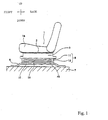
- Fig. 1 is a side view schematically showing a vehicle seat provided with a seat load measuring apparatus according to an embodiment of the present invention
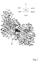
- Fig. 2 is an exploded perspective view showing the seat load measuring apparatus according to the embodiment of the present invention
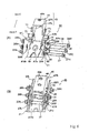
- Figs. 3(A), 3(B) are illustrations showing the seat load measuring apparatus of this embodiment in the assembled state thereof, wherein Fig. 3(A) is a plan view thereof and Fig. 3(B) is a sectional view taken along a line IIIB-IIIB of Fig. 3(A)
- Fig. 4 is an exploded perspective view showing a sensor portion of the seat load measuring apparatus of this embodiment
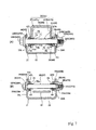
- 5(A), 5(B) are enlarged partial views of a portion about the sensor portion in the seat load measuring apparatus of this embodiment.
- the forward, backward, leftward, rightward, upward, and downward directions correspond to the forward, backward, leftward, rightward, upward, and downward directions of a vehicle.
- a vehicle seat 1 has a seat cushion 1a on which an occupant can sit, and a seat pan 2 made of a steel plate which is disposed beneath the seat cushion 1a to entirely cover the under surface of the seat cushion 1a.
- a pair of side frames 3 extend downwardly from the seat pan 2 and are spaced apart from each other at a predetermined distance in the lateral (left-to-right) direction of the vehicle.
- Each side frame 3 is disposed to extend in the longitudinal (front-to-rear) direction of the vehicle.
- Each seat rail 8 is a combination of an upper rail 11 which is fixed to the lower end of the side frame 3 and a lower rail 15 which is arranged to be slideable relative to the upper rail 11 in the longitudinal direction of the vehicle.
- Each seat load measuring apparatus is connected to each lower rail 15 via a pair of front and rear rail brackets 35, 45.
- the seat load measuring apparatuses 10 are fixed to a pair of seat brackets 9 (only one of which is shown in Fig. 1) which are secured to a vehicle floor 7 and spaced apart from each other in the lateral direction of the vehicle.
- the seat load measuring apparatus 10 comprises a base frame 21 which extends in the longitudinal direction of the vehicle.
- the base frame 21 is composed of a base bottom 22 and base side walls 23L, 23R such that the base frame 21 is formed to have an upward U-shaped cross section (to have an open top). It should be noted that the base frame 21 may be formed to have a downward U-shaped cross section (to have an open bottom).
- the base frame 21 is provided near the front and rear ends thereof with mounting portions 30 and 40 relative to the vehicle body or the seat rails, respectively, and is provided at the center thereof with a sensor portion 50.
- the mounting portion 30 at the front end side of the base frame 21 is provided with a hole 22A (see Fig. 2) which is formed in the base bottom 22 at a predetermined location and is provided with elongated holes 32, pivot holes 33, and small apertures 31 which are formed in front end portions of the left and right base side walls 23L, 23R, respectively to correspond to those of the other base side wall 23L, 23R.
- the hole 22A is a hole for insertion of a riveting jig J.
- the elongate holes 32 are long in the vertical direction.
- a stopper bolt (pivot pin) 24 is inserted through the elongated holes 32.
- the stopper bolt 24 is a pivot pin which pivotally supports a rail bracket 35 and a Z arm 61Fr together and transmits a seat load to the Z arm 61Fr as shown in Fig. 3(B).
- the stopper bolt 24 is provided at one end with a hexagon head 24H, at the other end with a threaded portion 24S, and at the middle with a smooth cylindrical surface.
- the stopper bolt 24 is inserted through the elongated holes 32 and is then fixed by a stopper nut 24N via a stopper washer 24W.
- the pivot holes 33 are formed in positions closer to the center than the positions of the elongated holes 32.
- Formed around the pivot holes 33 are counter bores 33a formed in outer surfaces of the base side walls 23L, 23R and convexities 33b formed in the inner surfaces of the base side walls 23L, 23R.
- Inserted into the pivot holes 33 is a pivot bolt (pivot pin) 25 as shown in Fig. 2, Figs. 3(a), 3(B), and Fig. 7(B).
- the pivot bolt 25 is a pivot pin for supporting the Z arm 61Fr such that the Z arm 61Fr is pivotable relative to the base frame 21.
- the Z arm 61Fr pivots about the pivot bolt 25.
- the pivot bolt 25 is provided at one end with a hexagon head 25H, at the other end with a threaded portion 25S, and at the middle with a smooth cylindrical surface.
- the pivot bolt 25 is inserted through the pivot holes 33 and is then fixed by a pivot nut 25N.
- stopper bolt 24 and the pivot bolt 25 are of type to be fastened by the nuts 24N and 25N, these are easily and securely attached.
- the small apertures 31 formed adjacent to the pivot holes 33 are service windows for observation of the assembling state.
- the Z arm 61Fr is arranged inside the base frame 21 at the mounting portion 30 at the front end side of the base frame 21.
- the Z arm 61Fr has a portion on the rear side from the middle portion, which is forked into two plate-shape branches 66, when seen in plan view.
- the Z arm 61Fr has a portion on the front side, where arm side plates 67L, 67R are formed to stand upwardly from the left and right edges.
- the Z arm 61Fr is assembled between the base side walls 23L and 23R to extend along the inner surfaces of the base side walls 23L and 23R. There are gaps between the arm side plate 67L and the base side wall 23L and between the arm side plate 67R and the base side wall 23R so that flanges of sleeves 70 (71, 72) and 75 are disposed in these gaps.
- each of the side plates 67L, 67R of the Z arm 61Fr is provided with holes 62, 63 formed at locations corresponding to the elongate hole 32 and the pivot hole 33 of the base side wall 23L, 23R.
- Figs. 3(A), 3(B), Fig. 7(A), 7(B) inserted into the holes 62 (corresponding to the elongate holes 32 of the base frame 21) formed near the front end of the Z arm 61Fr is the stopper bolt 24.
- Inserted into the holes 63 (corresponding to the pivot holes 33 of the base frame 21) at the middle portion side of the Z arm 61Fr is the pivot bolt 25.
- the main task of the stopper bolt 24 is connecting the rail bracket 35 and the Z arm 61Fr in such a manner as to allow the pivotal movement of them and transmitting a seat load to the Z arm 61Fr as can be seen in Fig. 3(B). Since there are gaps between the stopper bolt 24 and the elongated holes 32, the base frame 21 and the stopper bolt 24 are normally prevented from interfering each other.
- the main task of the pivot bolt 25 is pivotally supporting the Z arm 61Fr relative to the base frame 21, whereby the Z arm 61 can pivot about the pivot bolt 25.
- the branches 66 of the Z arm 61Fr are designed to have smaller distance therebetween at the middle portion side. As shown in Fig. 2 and Figs. 3(A), 3(B), a ridge portion 61a is formed in the middle portion of the Z arm 61Fr, thereby increasing the strength of the Z arm 61Fr. Action portions at the ends (rear ends) of the branches 66 are covered by resin arm caps 66A, respectively.
- the resin arm caps 66A are sandwiched between wings 53a, 55a of upper and lower half arms 53, 55 (see Fig. 5(B)) of the load sensor 51 (as will be described later).
- the Z arm 61Fr slightly pivots, whereby the action end portions transmit the load to the sensor plate 52 (corresponding to the distortion member of the present invention) through the half arms 53, 55.
- the front rail bracket 35 is assembled inside the Z arm 61Fr.
- the front rail bracket 35 is composed of a flat top portion 36 and side walls 37L, 37R extending downwardly from the left and right edges of the top portion 36 in such a manner as to have an inverted U-shaped cross section.
- the lower rail 15 of the seat rail 8 is mounted on the upper surface of the top portion 36.
- the top portion 36 has a hole 36a formed therein through which a rivet fastening the top portion 36 and the seat rail 8 together is inserted.
- Each of the left and right side plates 37L, 37R of the front rail bracket 35 is substantially formed in a trapezoidal shape.
- the left and right side plates 37L, 37R have holes 38, respectively, to face each other.
- the holes 38 are formed at locations corresponding to the elongate holes 32 of the base side walls 23L, 23R and the holes 62 of the Z arm 61Fr.
- the stopper bolt 24 In the assembled state, inserted into the holes 38 is the stopper bolt 24 as shown in Figs. 3(A), 3(B), and Fig. 7(A).
- double sleeves 70 are fitted around the outer periphery of the cylindrical portion of the stopper bolt 24.
- Each of the double sleeve 70 comprises an inner sleeve 71 which is longer and an outer sleeve 72 which is shorter and fitted around the inner sleeve 71.
- the sleeves 71, 72 have flanges 71a, 72a at one ends and tapered portions 71b, 72b (see Fig. 8) at the other ends.
- the inner surfaces of the sleeves 71, 72 and the end faces of the flanges 71a, 72a are coated with Teflon®. It should be noted that Fig. 8 shows the inclinations of the tapered portions 71b, 72b in an exaggerated way.
- the inner sleeve 71 of the double sleeve 70 is fitted into a space between the shaft portion of the stopper bolt 24 and the hole 62 of the arm side plate 67L (67R) and a space between the shaft portion of the stopper bolt 24 and the hole 38 of the front rail bracket 35.
- the outer sleeve 72 is press fitted between the outer periphery of the inner sleeve 71 and the hole 38 of the front rail bracket 35.
- the flange 72a of the outer sleeve 72 is disposed between the arm side plate 67L (67R) and the side plate 37L (37R) of the front rail bracket 35.
- the flange 71a of the inner sleeve 71 abuts on the outer surface of the arm side plate 67L (67R).
- the inner sleeve 71 Since the inner sleeve 71 is press fitted into the hole 62 of the arm side plate 67L (67R), the inner sleeve 71 is prevented from rattling within the hole 62. Between the inner sleeve 71 and the stopper bolt 24 inserted through the inner bore of the inner sleeve 71, the tapered portion 71b of the inner sleeve 71 is elastically in contact with and supports the outer periphery of the stopper bolt 24. Therefore, while there is a clearance between a portion of the inner sleeve 71 other than the tapered portion 71b and the stopper bolt 24, the stopper bolt 24 is prevented from rattling within the inner bore of the inner sleeve 71.
- the tapered portion 72b of the outer sleeve 72 is elastically in contact with and supports the outer periphery of the inner sleeve 71. Therefore, while there is a clearance between a portion of the outer sleeve 72 other than the tapered portion 72b and the inner sleeve 72, the inner sleeve 71 is prevented from ratting within the inner bore of the outer sleeve 72.
- sleeves 75 are fitted around the outer periphery of the cylindrical portion of the pivot bolt 25.
- Each sleeve 75 has a flange 75a at its one end and a tapered portion 75b at its other end.
- the inner surface of the sleeve 75 and the end face of the flange 75a are coated with Teflon®.
- the inner sleeve 75 is prevented from rattling within the hole 63.
- the tapered portion 75b of the sleeve 75 is elastically in contact with and supports the outer periphery of the pivot bolt 25. Therefore, while there is a clearance between a portion of the sleeve 75 other than the tapered portion 75b and the pivot bolt 25, the stopper bolt 25 is prevented from rattling within the inner bore of the sleeve 75. Accordingly, the occurrence of noise generated due to the rattling of the pivot bolt 25 and/or the Z arm 61Fr when the load applied to the seat is varied can be prevented.
- the different point of the mounting portion 40 at the rear end side of the base frame from the aforementioned mounting portion 30 at the front end side of the base frame is that the mounting portion 40 at the rear end side of the base frame has two stopper bolts as the protective mechanism for transmitting excessive load from the rear rail bracket 45 to the base frame 21, thereby having higher loading capacity than the mounting portion 30 at the front end side of the base frame.
- the mounting portion 40 at the rear end side is provided with a front-side first stopper bolt 26 and a rear-side second stopper bolt 28.
- the front-side stopper bolt 26 (hereinafter, sometime called as “front stopper bolt 26") has the same components as those of the stopper bolt 24 of the mounting portion 30 at the front side mentioned above so that the same appendices as those of the numeral "24" are added to the numeral "26" and detail descriptions of the components are omitted.
- the rear-side second stopper bolt 28 (hereinafter, sometime called as “rear stopper bolt 28") is an additional reinforcing member which is not used in the mounting portion 30 at the front end side. The following description will center on the structure of the second stopper bolt 28 as an additional member and the related components.
- the base frame 21 has circular holes 44, adjacent to elongate holes 42 and nearer to the rear end thereof than the elongate holes 42, through which the rear stopper bolt 28 is inserted.
- Each circular hole 44 has such a diameter as to allow the insertion of the shaft portion of the rear stopper bolt 28.
- the rear stopper bolt 28 is provided at one end with a hexagon head 28H, at the other end with a threaded portion 28S, and at the middle with a smooth cylindrical surface.
- the rear stopper bolt 28 is fixed by a stopper nut 28N as shown in Fig. 3(A) and Fig. 6(B) when assembled.
- a Z arm 61Rr to be arranged inside the rear side portion of the base frame 21 has the same structure as the aforementioned Z arm 61Fr arranged in the front side portion of the base frame and comprises branches 66, arm side plates 67L, 67R, and arm caps 66A of action portions at the ends thereof.
- the Z arm 61Fr at the front end side of the base frame and the Z arm 61Rr at the rear end side of the base frame are arranged symmetrically about the center of the base.
- the rear rail bracket 45 is arranged inside the Z arm 61Rr. As shown in Fig. 2 and Figs. 6(A), 6(B), the rear rail bracket 45 is composed of a flat top portion 46 and side walls 47L, 47R extending downwardly from the left and right edges of the top portion 46 in such a manner as to have an inverted U-shaped cross section.
- the lower rail 15 of the seat rail 8 is mounted on the upper surface of the top portion 46.
- the top portion 46 has two hole 46a formed therein through which rivets 15R (see Figs. 10(A), 10(B)) fastening the top portion 46 and the lower rail 15 together are inserted.
- Each of the side plates 47L, 47R of the rear rail bracket 45 is substantially formed in a trapezoidal shape.
- Each of the left and right side plates 47L, 47R have holes 48 and elongate holes 49 at locations corresponding to the elongate holes 42 and the circular holes 44 of the base side walls 23L, 23R.
- the front stopper bolt 26 is inserted through the holes 48 (corresponding to the elongate holes 42 and the holes 62 of the Z arm 61Rr).
- double sleeves 70 are inserted through spaces between the front stopper bolt 26 and the hole 48 of the rear rail bracket 45 and between the front stopper bolt 26 and the hole 62 of the Z arm 61Rr similarly to the aforementioned case.
- the front stopper bolt 26 is loosely fitted to the elongate holes 42 of the base frame 21.
- the rear stopper bolt 28 is inserted through the elongate holes 49 (corresponding to the circular holes 44) of the rear rail bracket 45 with suitable predetermined gaps.
- the works of the mounting portion 40 at the rear end side of the base frame 21 will be described later.
- each of the left and right base side walls 23L, 23R is formed with a notch 23X at the middle in the longitudinal direction of the base frame 21.
- a protector 29 which overhangs in the leftward direction is fixed to the outer surface of the left base side wall 23L.
- the protector 29 is formed by bending a band-like plate to have a protecting portion 29a, formed in a U-like or C-like shape, and mounting flanges 29b, 29c formed on both sides of the protecting portion 29a.
- a load sensor 51 is installed inside the notches 23X of the base frame 21 and the protector 29.
- the protecting portion 29a encloses and protects a portion of the load sensor 51 projecting outside of the base side wall 23L through the notch 23X of the base side wall 23L, i.e. a connector receiving portion (see Fig. 11) of the sensor plate 52 and a connector casing 57a (see Fig. 11 and Fig. 12) of a sensor-side connector 57.
- the connector casing 57a is attached to the upper surface of the connector receiving portion by casing fixing screws 101, 102 (see Fig. 11).
- the level of the upper edge of the protector 29 is higher than any of the level of the upper surface of the sensor plate 52, the level of the upper surface of the connector casing 57a, and the level of the upper surface of the sensor-side connector 57.
- the level of the lower edge of the protector 29 is lower than any of the level of the lower surface of the sensor plate 52, the level of the lower surface of the connector casing 57a, and the level of the lower surface of the sensor-side connector 57.
- the protector 29 can securely protect precision components such as the sensor plate 52 and the connector 57 of the seat load measuring apparatus 10 even if the base frame in which the seat load measuring apparatus 10 and the protector 29 are assembled is dropped when the base frame 21 is mounted to a vehicle or during transportation.
- a cover (not shown) is preferably provided to cover the upper side of the protector 29 in order to further ensure the protection.
- the lower side of the protector 29 is also open. However, since the object matters are easily removed from the inside of the protector 29 even if object matters enter into the protector 29, there is no necessary to cover the lower side of the protector 29.
- the connector casing 57a has an opening 57f. Disposed around the peripheral edge, on the side to be in contact with the sensor plate 52, of the opening 57f is a watertight packing 57g. With the watertight packing 57g, the connector casing 57a and the sensor plate 52 can be water-tightly sealed. When potting is made on the opening 57f, the watertight packing 57g also functions to prevent leakage of potting material.
- the opening 57f is covered by resin, on the side not the side to be in contact with the sensor plate 52, in order to prevent object matters from entering through the opening 57f.
- watertight packings 109, 110 are provided to the casing of the cable-side connector 104 as shown in Fig. 13 and Fig. 14. By these watertight packings 109, 110, the upper side of the cable-side connector 104 is water-tightly sealed.
- Fig. 12 and Fig. 13 show an example of structure for mounting the sensor plate 52 to the base frame 21, this example being different from the mounting structure composed of the components shown in Fig. 4. That is, as shown in Fig. 13, the sensor plate 52 can be attached to the base frame 21 just by screwing bolts into a mounting base provided on the base bottom 22.
- the sensor plate 52 as the main component of the load sensor 51 is a spring member which is a rectangular plate having two necks 52c as a whole.
- the sensor-side connector 57 is fixed by a vis 57a (see Fig. 5(A)).
- ECU electronice control unit
- an insulating layer for electrical insulating, a wiring layer, and a resistive layer are formed on the sensor plate 52.
- four strain resistors 105, 106, 107, 108 are formed as strain gauges which cooperate together to compose the load sensor 51.
- the four strain resistors 105, 106, 107, 108 are connected to each other to form a bridge circuit which is connected to the connector 57.
- terminals 57b, 57c of the connector 57 are connected to the conductors 52a, 52b of the bridge circuit formed on the sensor plate 52 by the strain resistors.
- ends 57d, 57e, opposite to the side connected to the conductors 52a, 52b, of the terminals 57b, 57c of the connector 57 are disposed to project downwardly, thereby forming a male connector 57.
- the terminals 57b, 57c of the connector 57 are press-fitted into the connector casing 57a and are thus united with the connector casing 57a.
- the connector 57 is composed of a male connector 57 having terminals projecting downwardly. The entry of the male connector 57 faces the open bottom of the protector 29.
- the cable 103 to be connected to the ECU is provided with the cable-side connector 104.
- the cable-side connector 104 is composed of a female connector 57 which is detachable relative to the male connector 57.
- the cable 103 to be connected to the ECU is connected to the cable-side connector 104. Therefore, in a state that the seat load measuring apparatus 10 is attached to the base frame 21, the cable-side connector 104 is inserted into the male connector 57 through the open bottom of the protector 29, thereby establishing the electrical connection. On the other hand, the cable-side connector 104 inserted in the male connector 57 can be detached from the male connector 57. Contrary to the aforementioned case, the connector 57 of the connector casing 57a side may be composed of a female connector and the connector of the cable 103 side may be composed of a male connector.
- the load sensor 51 and the cable 103 to be connected to the ECU are structured to be detachable from each other by using a male connector and a female connector, the commonization of the load sensor 51 and the connector casing 57a relative to various kinds of motor vehicles is achieved. Only required is preparing the cable 103 having a length corresponding to the kind of vehicle. Therefore, the seat load measuring apparatus 10 can be easily and inexpensively adopted to various kinds of motor vehicles.
- the load sensor 51 can be effectively protected and the connection and disconnection between the ECU and the load sensor 51 can be facilitated.
- the seat load measuring apparatus 10 can be easily and inexpensively adopted to various kinds of motor vehicles. Moreover, it is not required to form hole(s) and groove(s) for insertion of the cable-side connector 104, thus further simplifying the manufacture and reducing the cost.
- connection of the cable-side connector 104 is achieved by utilizing the open bottom of the protector 29
- connection of the cable-side connector may be achieved by utilizing the open top of the protector 29.
- the entry of the sensor-side connector 57 is arranged to face upwardly.
- a protector 29 which is open in at least one side in the vertical direction of the vehicle a protector 29 which is open in at least one side in the longitudinal direction of the vehicle or a protector 29 which is open in at least one side in the lateral direction of the vehicle may be employed.
- a protector 29 which is open in at least one side in the diagonal direction from upper front to lower back or from lower front to upper back, a protector 29 which is open in at least one side in the diagonal direction from upper left to lower right or from lower left to upper right, or a protector 29 which is open in at least one side in the diagonal direction from forward left to backward right or from backward left to forward right may be employed. That is, the protector 29 of the present invention may be a protector which is open in at least one side in any of the vertical direction, the longitudinal direction, the lateral direction, the diagonal direction from upper front to lower back or from lower front to upper back, the diagonal direction from upper left to lower right or from lower left to upper right, and the diagonal direction from forward left to backward right or from backward left to forward right. However, it is preferable to utilize the open bottom of the protector 29 for connection of the cable-side connector 104, because of the aforementioned reason.
- the male connector 57 and the cable-side connector 104 can be delivered in the connected state.
- the male connector 57 and the cable-side connector 104 are allowed to be connected during the assembly of a vehicle body by a car manufacturer, the male connector 57 and the cable-side connector 104 can be delivered separately.
- the flexibility during manufacturing process is improved. In this manner, a seat load measuring apparatus which can be effectively adopted in various kinds of motor vehicles and has improved workability and improved productivity can be provided.
- the load may be obtained by conversion from deflection of the sensor plate 52 detected by other elements such as electrical capacitance pressure sensors or Hall elements,.
- a standing center post 59 is fixed to the base bottom 22 at the middle in the longitudinal direction of the base bottom 22.
- the center post 59 is a substantially cylindrical member having bolts B1, B2 projecting upwardly and downwardly.
- the lower bolt B2 of the center post 59 penetrates the base bottom 22 and is screwed into a center nut 59N.
- the upper bolt B 1 of the center post 59 penetrates a central hole 52e (see Fig. 4) of the sensor plate 52 and is fixed by the center nut 58N via a center washer 59W.
- the center of the sensor plate 52 is solidly fixed to the base bottom 22 of the base frame 21 through the center post 59.
- the structure of the load sensor 51 will be further described.
- the half arms 53, 55 are two pairs to be arranged at front and rear ends of the sensor plate 52, respectively. As for each pair, the half arms 53, 55 are arranged above and below the sensor plate 52 to clamp the sensor plate 52 as shown in Fig. 4 and Fig. 5(B). Since the half arms 53, 55 have same configuration, a description will be made as only the half arm 55 arranged below the sensor plate 52.
- the half arm 55 is a plate member of a rectangular shape and is provided with a mounting hole 55e formed in the center of the base thereof.
- the half arm 55 has wings 55a which project in the rightward and leftward directions from edges thereof near the center.
- Levee-like supports 55b are formed on the backs of the wings 55a to extend in the rightward and leftward directions.
- the top of each support 55b is slightly edged.
- the bases of the upper half arm 53 and the lower half arm 55 fully abut on the surfaces of the sensor plate 52 and are fixed by bolts 56B and nuts 56N.
- the wings 53a, 55a of the upper and lower half arms 53, 55 are arranged in such a manner that the supports 53b, 55b confront each other. Sandwiched between the supports 53b, 55b are the arm caps 66A of the Z arm action portions.
- the supports 53b, 55b are positioned at the necks 52c of the sensor plate 52.
- the actions of the upper and lower half arms 53, 55, the sensor plate 52, and the Z arm 61 when load is applied to the seat load measuring apparatus 10 are described in detail, for example, in Japanese Patent Unexamined Publication No. 2000-258223 and should be understood by reading the publication, so the description will be omitted here.
- the Load applied to the seat load measuring apparatus 10 is obtained by the computation of the ECU on the basis of the measured distortion of the sensor plate 52.
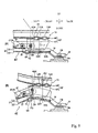
- Figs. 9(A), 9(B) show an example of a rear end portion of a base frame of a seat load measuring apparatus as a comparative example relative to the present invention, wherein Fig. 9(A) is a sectional view showing the normal state and Fig. 9(B) is a sectional view showing a state after a force in a direction of lifting the seat is exerted.
- Figs. 10(A), 10(B) show the rear end portion of the base frame of the seat load measuring apparatus according to the embodiment of the present invention, wherein Fig. 10(A) is a sectional view showing the normal state and Fig. 10(B) is a sectional view showing a state after a force in a direction of lifting the seat is exerted.
- a single stopper bolt i.e. the front stopper bolt 26 is provided for transmitting an excessive load exerted on a rear rail bracket 45' to a base frame 21.
- the stopper bolt 26 is perfectly fitted relative to the rear rail bracket 45' and a Z arm 61Rr and is loosely fitted in elongate holes 42 of the base frame 21.
- a lower surface of a lower rail 15 and a top portion 46' of the rear rail bracket 45' are connected to each other by two rivets 15R aligned in the longitudinal direction.
- a base bottom 22 of the base frame 21 is connected to a seat bracket (leg) 9' by a single rivet 9R at a front side (left side in Figs. 9(A), 9(B)) and a welded portion W at a rear side.
- the welded portion W is more securely welded, for example by continuous welding, than spot welding of the present invention shown in Fig. 10 as described later.
- the seat bracket 9' is fixed to a vehicle floor 7 by a bolt 7B.
- the vertical center line between the two upper rivets 15R and the vertical center line of the stopper bolt 26 are shifted from each other as shown in the drawings.
- the seat bracket 9' has two holes at locations corresponding to two holes 22A formed in the aforementioned base bottom 22.
- the holes 22A are provided for insertion of riveting jig J (shown by a virtual line in Fig. 9(A)).
- the riveting jig J is used for driving the rivets 15R for connecting the rail 15 and the rail bracket 45' after the seat load measuring apparatus and the seat rail 15 are put on the seat bracket 9'.
- bolts and nuts which can be inserted into the holes 22A may be used to connect the rail 15 and the rail bracket 45'.
- two stopper bolts i.e. the front and rear stopper bolts 26, 28, are provided for transmitting an excessive load exerted on the rear rail bracket 45 to the base frame 21.
- the front stopper bolt 26 is perfectly fitted relative to the rear rail bracket 45 and the Z arm 61Rr and is loosely fitted in the elongate holes 42 of the base frame 21 (see Fig. 7(A)).
- the rear stopper bolt 28 is perfectly fitted relative to the base frame 21 and is loosely fitted in the elongate holes 49 of the rear rail bracket (see also Fig. 6(A)).
- a lower surface of the lower rail 15 and the top portion 46 of the rear rail bracket 45 are connected to each other by two rivets 15R aligned in the longitudinal direction.
- the base bottom 22 of the base frame 21 is connected to the seat bracket 9 by a single rivet 9R at a front side (left side in Figs. 10(A), 10(B)) and spot welding portions SP (at two locations aligned in the lateral direction of the vehicle) at the middle.
- the seat bracket 9 has two holes at locations corresponding to the holes 22A (see also Fig. 2) formed in the base bottom 22. Similarly to the above case, the holes 22A are provided for insertion of a riveting jig.
- the vertical center line between the upper two rivets 15R and the vertical center line of the front stopper bolt 26 are shifted from each other, the vertical center line between the rivets 15R is substantially the same as the vertical center line of the rear stopper bolt 28.
- the load applied to the seat rail 15 is transmitted directly to the seat bracket 9 via the rail bracket 45 and the rear stopper bolt 28. Therefore, relatively simple structure is enough for the connection between the base frame 21 of the seat load measuring apparatus 10 and the seat bracket 9.
- the seat bracket 9 shown in Figs. 10(A), 10(B) has a fixed base 9a and connecting portions 9b extending diagonally from the fixing base 9a.
- the fixed base 9a is fixed to a vehicle floor 7 by a bolt 7B.
- the connecting portions 9b stand along the respective base side walls 23L and 23R.
- the connecting portions 9b are disposed in spaces (see Fig. 2 and Figs. 6(A), 6(B)) between the hexagonal head 28H of the rear stopper bolt 28 and the outer surface of the corresponding base side wall 23L, 23R and between the bearing surface of the stopper nut 28N and the outer surface of the corresponding base side wall 23L, 23R.
- the rear stopper bolt 28 penetrates the centers of the connecting portions 9b.
- the moment of inclining the seat is applied evenly to the two rivets 15R connecting the lower rail 15 and the rear rail bracket 45 so as to reduce the local load on the lower rail 15 and the rear rail bracket 45, thereby preventing the lower rail 15 and the rear rail bracket 45 from being deformed.
- the vertical center line between the upper two rivets 15R is substantially the same as the vertical center line of the rear stopper bolt 28 as described above, the force of breaking the rivets 15R and the moment of bending the lower rail 15 are reduced.
- the moment of inclining the lower rail 15 is transmitted to the seat bracket 9 via the rear stopper bolt 28 and is finally received by the vehicle floor 7.
- the load to the base frame 21 is reduced so as to restrain the base frame 21 from being deformed. In this manner, effect of the rising of the seat rear portion upon the mounting portion 40 is avoided.
- Figs. 16(A)-16(D) show a variation example of the rear end portion of the base frame of the seat load measuring apparatus shown in Figs. 10(A), 10(B), wherein Fig. 16(A) is a side sectional view showing the normal state, Fig. 16(B) is a sectional view taken along al line XVIB-XVIB of Fig. 16(A), Fig. 16(C) is a side sectional view showing a state after a force in a direction of lifting the seat is exerted, and Fig. 16(D) is a sectional view taken along a line XVID-XVID of Fig. 16(C).
- Fig. 16(A) is a side sectional view showing the normal state
- Fig. 16(B) is a sectional view taken along al line XVIB-XVIB of Fig. 16(A)
- Fig. 16(C) is a side sectional view showing a state after a force in a direction of
- Figs. 10(A), 10(B) The embodiment shown in Figs. 10(A), 10(B) is structured such that, when a large load acts on the vehicle seat in the lifting direction, for example, in the event of a vehicle collision, the load is received by the two bolts, i.e. the first and second stopper bolts 26, 28.
- this variation example is structured such that the load is received by only one bolt, i.e. the second stopper bolt 28 as shown in Figs. 16(A), 16(B).
- the second stopper bolt 28 is positioned on the center line between the front and rear rivets 15R and 15R for fastening the rear rail bracket 45 and the lower rail 15 and is perfectly fitted relative to the base frame 21. Further, the second stopper bolt 28 is loosely fitted in the elongate holes 49 of the rear rail bracket 45 and also loosely fitted in circular holes 9c formed in the both side walls of the seat bracket 9.
- the first stopper bolt 26 can be omitted, that is, reducing the number of parts. Further, since the first stopper bolt 26 can be omitted, the configuration of the rear rail bracket 45 can be simplified such that it can be symmetrical about the position where the second stopper bolt 28 penetrates. Furthermore, since the second stopper bolt 28 is arranged at a position on the center line between the first and rear rivets 15R, 15R, no or little offset load or moment due to the offset load is exerted on the rear rail bracket 45. Therefore, since the load is applied nearly evenly to the front and rear rivets 15R, 15R, same rivets can be used for the front and rear rivets 15R, 15R, thus achieving the commonization of parts.
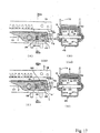
- Figs. 17(A)-17(D) show another variation example of the rear end portion of the base frame of the seat load measuring apparatus shown in Figs. 10(A), 10(B), wherein Fig. 17(A) is a side sectional view showing the normal state, Fig. 17(B) is a sectional view taken along al line XVIIB-XVIIB of Fig. 17(A), Fig. 17(C) is a side sectional view showing a state after a force in a direction of lifting the seat is exerted, and Fig. 17(D) is a sectional view taken along a line XVIID-XVIID of Fig. 17(C).
- Fig. 17(A) is a side sectional view showing the normal state
- Fig. 17(B) is a sectional view taken along al line XVIIB-XVIIB of Fig. 17(A)
- Fig. 17(C) is a side sectional view showing a state after a force in
- Figs. 16(A) through 16(D) is structured such that the base frame 21 is fixed to the vehicle floor 7 via the seat bracket 9 and the rear rail bracket 45 is fixed to the lower rail 15.
- this variation example is structured such that the base frame 21 is fixed to the lower rail 15 via the seat bracket 9 and the rear rail bracket 45 is fixed to the vehicle floor 7 as shown in Figs. 17(A) through 17(D).
- Fig. 18 is an exploded perspective view similar to Fig. 4, but showing a variation example of the sensor portion shown in Fig. 4. As the same components as those of the aforementioned embodiment are marked with the same numerals, detail description about the components will be omitted.
- the hole of the washer 58W, the center hole 52e of the sensor plate 52, and the hole of the center washer 59W are each formed in a rectangular shape.
- the hole 58W 1 of the washer 58W, the center hole 52e of the sensor plate 52, and the hole 59W 1 of the center washer 59W are each formed in a circular shape as shown in Fig. 18.
- Figs. 19(A), 19(B) show a variation example of the sensor portion of the seat load measuring apparatus, wherein Fig. 19(A) is a partial plan view similar to Fig. 12 and Fig. 19(B) is a sectional view similar to Fig. 13, taken along a line XIXB-XIXB of Fig. 19(A).
- Fig. 19(A) is a partial plan view similar to Fig. 12
- Fig. 19(B) is a sectional view similar to Fig. 13, taken along a line XIXB-XIXB of Fig. 19(A).
- the mounting structure of the sensor plate 52 relative to the base frame 21 are different from the mounting structure composed of the components shown in Fig. 4.
- the mounting structure of the sensor plate 52 relative to the base frame 21 is the same as the mounting structure composed of the components shown in Fig. 4, as shown in Figs. 19(A), 19(B).
- the seat load measuring apparatus 10 and the lower rail 15 or the seat bracket 9 are riveted together.
- the front stopper bolt 26 and the Z arm do not interfere the riveting work because the positions of the rivets are shifted from the front stopper bolt 26 and the front and rear ends of the Z arm 61.
- a cable for connecting a load sensor and a control unit can be designed to be detachable by employing a sensor-side connector and a cable-side connector, thereby achieving the commonization of the load sensor and the connector casing relative to various kinds of motor vehicles. Only required is preparing a cable having a length corresponding to the kind of motor vehicle. Therefore, the seat load measuring apparatus can be easily and inexpensively adopted to various kinds of motor vehicles.
- the load sensor can be effectively protected and the connection and disconnection between the load sensor and the cable can be facilitated.
- the seat load measuring apparatus can be easily and inexpensively adopted to various kinds of motor vehicles. Moreover, it is not required to form hole(s) and groove(s) for insertion of the cable-side connector, thus further simplifying the manufacture and reducing the cost.
- the senor-side connector and the cable-side connector can be delivered in the connected state.
- the connectors since the connectors are allowed to be connected during the assembly of a vehicle body by a car manufacturer, the connectors can be delivered separately. Moreover, the flexibility during manufacturing process is improved. In this manner, a seat load measuring apparatus which can be effectively adopted in various kinds of motor vehicles and has improved workability and improved productivity can be provided.
- the protector is formed just by bending a band-like plate. Therefore, the protector can be easily and inexpensively formed.
- a protective mechanism is provided so as to withstand large load exerted on the mounting portion of the seat load measuring apparatus disposed between a vehicle seat and a vehicle floor by a moment in a direction of lifting the rear portion of the vehicle seat.
- the seat load measuring apparatus can be easily and inexpensively adopted to various kinds of motor vehicles.
Landscapes
- Engineering & Computer Science (AREA)
- Mechanical Engineering (AREA)
- Aviation & Aerospace Engineering (AREA)
- Transportation (AREA)
- Physics & Mathematics (AREA)
- Mathematical Physics (AREA)
- Theoretical Computer Science (AREA)
- Computer Networks & Wireless Communication (AREA)
- General Physics & Mathematics (AREA)
- Seats For Vehicles (AREA)
Abstract
Description
Claims (4)
- A seat load measuring apparatus (10) comprising: a load sensor (51) detecting a load which is applied to a vehicle seat (1) by an occupant sitting on the vehicle seat (1); a control unit for calculating the load applied to said vehicle seat (1) on the basis of a detection signal of the load sensor (51); and a cable (103) connecting said load sensor (51) and said control unit to transmit the detection signal of said load sensor (51) to said control unit, wherein
said load sensor (51) has a distortion member which is distorted due to the load applied on said vehicle seat, strain gauges (105, 106, 107, 108) for detecting the distortion of said distortion member, and a sensor-side connector (57) connected to the strain gauges (105, 106, 107, 108), and
said cable (103) has a cable-side connector (104) which is detachably connected to said sensor-side connector (57). - A seat load measuring apparatus (10) as claimed in claim 1, further comprising a base frame (21) which is fixed to a vehicle floor (7) or a lower member of said vehicle seat (1) and on which the load applied on said vehicle seat (1) acts, said load sensor (51) being disposed on said base frame (21), wherein
said base frame (21) is provided with a protector (29) for protecting at least a part of said load sensor (51) including said sensor-side connector (57),
said protector (29) is open in at least one side in any of the vertical direction, the longitudinal direction, the lateral direction, the diagonal direction from upper front to lower back or from lower front to upper back, the diagonal direction from upper left to lower right or from lower left to upper right, and the diagonal direction from forward left to backward right or from backward left to forward right in a state mounted to the vehicle, and the entry of said sensor-side connector (57) faces the open side of said protector (29). - A seat load measuring apparatus as claimed in claim 2, wherein said protector (29) is formed by bending a band-like plate to have a protecting portion (29a) surrounding at least a part of said load sensor (51) including said sensor-side connector (57), and mounting portions (29b, 29c) to be attached to said base frame (21).
- A seat load measuring apparatus (10) as claimed in claim 2 or 3, further comprising:front-side and rear-side rail brackets (35, 45) which are disposed near the front and rear ends of said base frame (21), respectively, and are connected to a seat rail (8) which is slideable in the longitudinal direction of the vehicle; andarms (61Fr, 61Rr) which are disposed on a front portion and a rear portion of said base frame (21), respectively, to extend in the longitudinal direction and each of which is provided at its one end with a press portion for transmitting force to said strain gauges (105, 106, 107, 108) and at its other end with a connecting portion relative to said each rail bracket (35, 45), and whereinprotective mechanisms are disposed around said front and rear rail brackets (35, 45), respectively, and when the load applied between said base frame (21) and said rail brackets (35, 45) exceeds a predetermined value, said protective mechanisms directly transmit the excessive load between said base frame (21) and said rail brackets (35, 45) not through said arms (61Fr, 61Rr), andthe protective mechanism at the rear-side rail bracket (45) is provided with a reinforcing member for providing reinforcement against the load in a direction of lifting said base frame (21).
Applications Claiming Priority (6)
| Application Number | Priority Date | Filing Date | Title |
|---|---|---|---|
| JP2002240096 | 2002-08-21 | ||
| JP2002240096 | 2002-08-21 | ||
| JP2002324758 | 2002-11-08 | ||
| JP2002324758 | 2002-11-08 | ||
| JP2003191694A JP4183124B2 (en) | 2002-08-21 | 2003-07-04 | Seat load measuring device |
| JP2003191694 | 2003-07-04 |
Publications (2)
| Publication Number | Publication Date |
|---|---|
| EP1391706A1 true EP1391706A1 (en) | 2004-02-25 |
| EP1391706B1 EP1391706B1 (en) | 2006-06-07 |
Family
ID=31191884
Family Applications (1)
| Application Number | Title | Priority Date | Filing Date |
|---|---|---|---|
| EP03017656A Expired - Lifetime EP1391706B1 (en) | 2002-08-21 | 2003-08-13 | Seat load measuring apparatus |
Country Status (4)
| Country | Link |
|---|---|
| US (2) | US20040035224A1 (en) |
| EP (1) | EP1391706B1 (en) |
| JP (1) | JP4183124B2 (en) |
| DE (1) | DE60305811T2 (en) |
Families Citing this family (18)
| Publication number | Priority date | Publication date | Assignee | Title |
|---|---|---|---|---|
| JP2005098989A (en) * | 2003-09-05 | 2005-04-14 | Alps Electric Co Ltd | Load sensor |
| JP2005338038A (en) * | 2004-04-28 | 2005-12-08 | Takata Corp | Seat load measuring device, and occupant protection system using same |
| US7117756B2 (en) * | 2004-10-27 | 2006-10-10 | Lear Corporation | Load detecting vehicle seat assembly |
| JP2006298091A (en) * | 2005-04-19 | 2006-11-02 | Mazda Motor Corp | Vehicle seat device |
| US20070135983A1 (en) * | 2005-12-12 | 2007-06-14 | Automotive Systems Laboratory, Inc. | Initialization process for an occupant classification initialization |
| JP4137958B2 (en) * | 2006-06-23 | 2008-08-20 | アイシン精機株式会社 | Vehicle seat load detection device |
| JP2010527856A (en) * | 2007-05-29 | 2010-08-19 | ロードセンス テクノロジーズ コーポレイション | Pallet with weighing scale |
| US8258413B2 (en) * | 2008-11-19 | 2012-09-04 | Aisin Seiki Kabushiki Kaisha | Vehicle seat load detection device having interspace to receive projecting portion scraped off from press-fitted shaft member |
| US20100266246A1 (en) * | 2009-04-17 | 2010-10-21 | Laird Technologies, Inc. | Emi shielding and/or grounding gaskets |
| JP5621459B2 (en) * | 2010-09-22 | 2014-11-12 | アイシン精機株式会社 | Vehicle seat device |
| US9151644B2 (en) * | 2011-07-28 | 2015-10-06 | Ts Tech Co., Ltd. | Load measurement sensor support structure |
| JP2013028269A (en) * | 2011-07-28 | 2013-02-07 | Ts Tech Co Ltd | Structure for mounting load measurement sensor |
| DE102013106410B4 (en) * | 2013-06-19 | 2015-02-12 | Johnson Controls Components Gmbh & Co. Kg | Device for seat tilt adjustment of a motor vehicle seat |
| JP6248555B2 (en) * | 2013-11-07 | 2017-12-20 | アイシン精機株式会社 | Vehicle seat device |
| JP6373778B2 (en) | 2015-03-11 | 2018-08-15 | アルプス電気株式会社 | Load sensor and load detection device |
| JP6611248B2 (en) * | 2016-02-16 | 2019-11-27 | アルプスアルパイン株式会社 | Load sensor |
| CN106989941A (en) * | 2017-03-30 | 2017-07-28 | 中车青岛四方车辆研究所有限公司 | Car lifting J-Horner lift unit load test TT&C system and method |
| JP6809375B2 (en) * | 2017-05-22 | 2021-01-06 | トヨタ紡織株式会社 | Fastening structure for vehicle seats and fasteners for vehicle seats |
Citations (6)
| Publication number | Priority date | Publication date | Assignee | Title |
|---|---|---|---|---|
| JPH06270727A (en) * | 1993-03-17 | 1994-09-27 | Ikeda Bussan Co Ltd | Seat slide device |
| EP0990565A1 (en) * | 1997-06-13 | 2000-04-05 | Takata Corporation | Device for detecting seat occupancy and air bag device for a motor vehicle |
| US6244116B1 (en) * | 1999-08-16 | 2001-06-12 | Cts Corporation | Automobile seat weight sensor |
| US6323444B1 (en) * | 1999-03-09 | 2001-11-27 | Takata Corporation | Seat weight measuring apparatus |
| EP1184232A2 (en) * | 2000-08-31 | 2002-03-06 | Toyota Jidosha Kabushiki Kaisha | Shunt of squib |
| US20020043789A1 (en) * | 2000-09-29 | 2002-04-18 | Harald Lichtinger | Weight classification system |
Family Cites Families (26)
| Publication number | Priority date | Publication date | Assignee | Title |
|---|---|---|---|---|
| US43789A (en) * | 1864-08-09 | Improvement in lumber-measurers | ||
| US3949822A (en) * | 1974-09-30 | 1976-04-13 | Jerry L. McCauley | Vehicle wheel weighing system |
| JPS63125310U (en) * | 1987-02-10 | 1988-08-16 | ||
| IT1240002B (en) * | 1990-04-20 | 1993-11-27 | Ramsey Italia | CONTINUOUS WEIGHING BRIDGE OF SOLID MATERIALS TRANSPORTED ON A CONVEYOR BELT |
| DE19702874A1 (en) * | 1997-01-27 | 1998-07-30 | Molex Elektronik Gmbh | Electrical connection device and method for assembling a component of a motor vehicle |
| US5841741A (en) * | 1997-04-14 | 1998-11-24 | Freeman; Michael J. | Automatic seamless branching story-telling apparatus |
| JP3655745B2 (en) * | 1998-04-16 | 2005-06-02 | タカタ株式会社 | Seat weight measuring device |
| JP3683712B2 (en) | 1998-06-05 | 2005-08-17 | タカタ株式会社 | Seat weight measuring device |
| KR20000028718A (en) * | 1998-10-22 | 2000-05-25 | 가이자끼 요이찌로 | Load measuring apparatus |
| AU2965800A (en) * | 1999-01-21 | 2000-08-07 | Hottinger Baldwin Measurements, Inc. | Tank weigh module with excess motion restraint |
| DE20004393U1 (en) * | 1999-03-09 | 2000-08-03 | Takata Corp., Minato-Ku, Tokio/Tokyo | Seat weight measuring device |
| JP4129336B2 (en) | 1999-03-09 | 2008-08-06 | タカタ株式会社 | Seat weight measuring device |
| JP3444810B2 (en) | 1999-03-09 | 2003-09-08 | タカタ株式会社 | Seat weight measuring device |
| JP2000258223A (en) | 1999-03-11 | 2000-09-22 | Mitsubishi Heavy Ind Ltd | Optical liquid level sensor |
| US6571657B1 (en) * | 1999-04-08 | 2003-06-03 | Applied Materials Inc. | Multiple blade robot adjustment apparatus and associated method |
| JP2001012998A (en) | 1999-05-20 | 2001-01-19 | Takata Corp | Sheet weight measuring apparatus |
| JP2001041813A (en) | 1999-07-27 | 2001-02-16 | Takata Corp | Seat weight measuring device |
| JP2001108513A (en) | 1999-09-21 | 2001-04-20 | Takata Corp | Seat load measuring device |
| JP2001304949A (en) | 2000-04-24 | 2001-10-31 | Takata Corp | Sheet weight-measuring device |
| ES2172397B1 (en) * | 2000-05-24 | 2003-12-16 | I Llongueras Jordi Galan | REFRIGUERATOR-LUBRICATOR COURSE RING. |
| DE10102995B4 (en) * | 2001-01-24 | 2006-05-24 | Robert Bosch Gmbh | Data bus for restraint in a vehicle |
| US6669505B2 (en) * | 2001-09-13 | 2003-12-30 | Siemens Vdo Automotive Corporation | Vehicle electronic control units |
| JP2003177052A (en) * | 2001-12-13 | 2003-06-27 | Takata Corp | Apparatus for measuring sheet weight |
| JP2004317400A (en) * | 2003-04-18 | 2004-11-11 | Takata Corp | Seat load measuring apparatus |
| JP2004317401A (en) * | 2003-04-18 | 2004-11-11 | Takata Corp | Seat load measuring apparatus |
| US7244896B2 (en) * | 2003-11-14 | 2007-07-17 | Tanita Corporation | Multipoint scale |
-
2003
- 2003-07-04 JP JP2003191694A patent/JP4183124B2/en not_active Expired - Fee Related
- 2003-08-13 DE DE60305811T patent/DE60305811T2/en not_active Expired - Lifetime
- 2003-08-13 EP EP03017656A patent/EP1391706B1/en not_active Expired - Lifetime
- 2003-08-20 US US10/644,042 patent/US20040035224A1/en not_active Abandoned
-
2007
- 2007-03-23 US US11/727,129 patent/US7399932B2/en not_active Expired - Fee Related
Patent Citations (6)
| Publication number | Priority date | Publication date | Assignee | Title |
|---|---|---|---|---|
| JPH06270727A (en) * | 1993-03-17 | 1994-09-27 | Ikeda Bussan Co Ltd | Seat slide device |
| EP0990565A1 (en) * | 1997-06-13 | 2000-04-05 | Takata Corporation | Device for detecting seat occupancy and air bag device for a motor vehicle |
| US6323444B1 (en) * | 1999-03-09 | 2001-11-27 | Takata Corporation | Seat weight measuring apparatus |
| US6244116B1 (en) * | 1999-08-16 | 2001-06-12 | Cts Corporation | Automobile seat weight sensor |
| EP1184232A2 (en) * | 2000-08-31 | 2002-03-06 | Toyota Jidosha Kabushiki Kaisha | Shunt of squib |
| US20020043789A1 (en) * | 2000-09-29 | 2002-04-18 | Harald Lichtinger | Weight classification system |
Non-Patent Citations (1)
| Title |
|---|
| PATENT ABSTRACTS OF JAPAN vol. 018, no. 682 (M - 1729) 22 December 1994 (1994-12-22) * |
Also Published As
| Publication number | Publication date |
|---|---|
| US20040035224A1 (en) | 2004-02-26 |
| DE60305811T2 (en) | 2007-06-28 |
| US20070209451A1 (en) | 2007-09-13 |
| EP1391706B1 (en) | 2006-06-07 |
| JP4183124B2 (en) | 2008-11-19 |
| JP2004205489A (en) | 2004-07-22 |
| US7399932B2 (en) | 2008-07-15 |
| DE60305811D1 (en) | 2006-07-20 |
Similar Documents
| Publication | Publication Date | Title |
|---|---|---|
| US7399932B2 (en) | Seat load measuring apparatus | |
| US6841741B2 (en) | Seat weight measuring apparatus | |
| US6323444B1 (en) | Seat weight measuring apparatus | |
| JP4221041B2 (en) | Vehicle seat device provided with load detection device | |
| EP1930209B1 (en) | Occupant weight measurement device for vehicle seat and installation structure for load sensor | |
| US6586948B1 (en) | Vehicle seat weight measuring device | |
| JP3904913B2 (en) | Load detection structure for vehicle seat | |
| EP1172262B1 (en) | Seat load sensing apparatus | |
| JP2001108513A (en) | Seat load measuring device | |
| JP4050729B2 (en) | Vehicle seat occupant weight measurement device | |
| US6835899B2 (en) | Load sensing assembly for a vehicle seat | |
| US6759603B2 (en) | Weight sensor assembly with overload spring | |
| JP5003430B2 (en) | Vehicle seat load detection device | |
| US9400206B2 (en) | Weight detection sensor and vehicle seat apparatus including plural strain detection elements | |
| US9389116B2 (en) | Weight detection sensor and vehicle seat apparatus including a strain body between the floor and the vehicle seat | |
| US20040231435A1 (en) | Seat load measuring apparatus | |
| JP2006003146A (en) | Seat load measurement device and occupant protection system using it | |
| JP4171340B2 (en) | Seat load measuring device | |
| US20050242554A1 (en) | Seat load measuring device and occupant protection system using the same | |
| JP4669637B2 (en) | Seat weight measuring device | |
| US20040232751A1 (en) | Adjustable seat with integrated occupant weight sensors | |
| JP2005254926A (en) | Load sensor for vehicle seat and vehicle seat | |
| JP4676722B2 (en) | Load sensor mounting structure | |
| JP2006038491A (en) | Occupant weight measuring instrument for vehicular seat |
Legal Events
| Date | Code | Title | Description |
|---|---|---|---|
| PUAI | Public reference made under article 153(3) epc to a published international application that has entered the european phase |
Free format text: ORIGINAL CODE: 0009012 |
|
| AK | Designated contracting states |
Kind code of ref document: A1 Designated state(s): AT BE BG CH CY CZ DE DK EE ES FI FR GB GR HU IE IT LI LU MC NL PT RO SE SI SK TR |
|
| AX | Request for extension of the european patent |
Extension state: AL LT LV MK |
|
| 17P | Request for examination filed |
Effective date: 20040823 |
|
| AKX | Designation fees paid |
Designated state(s): DE FR GB SE |
|
| 17Q | First examination report despatched |
Effective date: 20041126 |
|
| GRAP | Despatch of communication of intention to grant a patent |
Free format text: ORIGINAL CODE: EPIDOSNIGR1 |
|
| GRAS | Grant fee paid |
Free format text: ORIGINAL CODE: EPIDOSNIGR3 |
|
| GRAA | (expected) grant |
Free format text: ORIGINAL CODE: 0009210 |
|
| AK | Designated contracting states |
Kind code of ref document: B1 Designated state(s): DE FR GB SE |
|
| REG | Reference to a national code |
Ref country code: GB Ref legal event code: FG4D |
|
| REF | Corresponds to: |
Ref document number: 60305811 Country of ref document: DE Date of ref document: 20060720 Kind code of ref document: P |
|
| REG | Reference to a national code |
Ref country code: SE Ref legal event code: TRGR |
|
| ET | Fr: translation filed | ||
| PLBE | No opposition filed within time limit |
Free format text: ORIGINAL CODE: 0009261 |
|
| STAA | Information on the status of an ep patent application or granted ep patent |
Free format text: STATUS: NO OPPOSITION FILED WITHIN TIME LIMIT |
|
| 26N | No opposition filed |
Effective date: 20070308 |
|
| PGFP | Annual fee paid to national office [announced via postgrant information from national office to epo] |
Ref country code: SE Payment date: 20070807 Year of fee payment: 5 |
|
| PGFP | Annual fee paid to national office [announced via postgrant information from national office to epo] |
Ref country code: FR Payment date: 20070808 Year of fee payment: 5 |
|
| EUG | Se: european patent has lapsed | ||
| REG | Reference to a national code |
Ref country code: FR Ref legal event code: ST Effective date: 20090430 |
|
| PG25 | Lapsed in a contracting state [announced via postgrant information from national office to epo] |
Ref country code: FR Free format text: LAPSE BECAUSE OF NON-PAYMENT OF DUE FEES Effective date: 20080901 |
|
| PG25 | Lapsed in a contracting state [announced via postgrant information from national office to epo] |
Ref country code: SE Free format text: LAPSE BECAUSE OF NON-PAYMENT OF DUE FEES Effective date: 20080814 |
|
| PGFP | Annual fee paid to national office [announced via postgrant information from national office to epo] |
Ref country code: DE Payment date: 20130807 Year of fee payment: 11 |
|
| PGFP | Annual fee paid to national office [announced via postgrant information from national office to epo] |
Ref country code: GB Payment date: 20130807 Year of fee payment: 11 |
|
| REG | Reference to a national code |
Ref country code: DE Ref legal event code: R119 Ref document number: 60305811 Country of ref document: DE |
|
| GBPC | Gb: european patent ceased through non-payment of renewal fee |
Effective date: 20140813 |
|
| REG | Reference to a national code |
Ref country code: DE Ref legal event code: R119 Ref document number: 60305811 Country of ref document: DE Effective date: 20150303 |
|
| PG25 | Lapsed in a contracting state [announced via postgrant information from national office to epo] |
Ref country code: GB Free format text: LAPSE BECAUSE OF NON-PAYMENT OF DUE FEES Effective date: 20140813 Ref country code: DE Free format text: LAPSE BECAUSE OF NON-PAYMENT OF DUE FEES Effective date: 20150303 |