US6669505B2 - Vehicle electronic control units - Google Patents
Vehicle electronic control units Download PDFInfo
- Publication number
- US6669505B2 US6669505B2 US10/206,573 US20657302A US6669505B2 US 6669505 B2 US6669505 B2 US 6669505B2 US 20657302 A US20657302 A US 20657302A US 6669505 B2 US6669505 B2 US 6669505B2
- Authority
- US
- United States
- Prior art keywords
- housing
- electronic control
- control unit
- ecu
- recited
- Prior art date
- Legal status (The legal status is an assumption and is not a legal conclusion. Google has not performed a legal analysis and makes no representation as to the accuracy of the status listed.)
- Expired - Fee Related
Links
Images


Classifications
-
- B—PERFORMING OPERATIONS; TRANSPORTING
- B60—VEHICLES IN GENERAL
- B60R—VEHICLES, VEHICLE FITTINGS, OR VEHICLE PARTS, NOT OTHERWISE PROVIDED FOR
- B60R16/00—Electric or fluid circuits specially adapted for vehicles and not otherwise provided for; Arrangement of elements of electric or fluid circuits specially adapted for vehicles and not otherwise provided for
- B60R16/02—Electric or fluid circuits specially adapted for vehicles and not otherwise provided for; Arrangement of elements of electric or fluid circuits specially adapted for vehicles and not otherwise provided for electric constitutive elements
- B60R16/023—Electric or fluid circuits specially adapted for vehicles and not otherwise provided for; Arrangement of elements of electric or fluid circuits specially adapted for vehicles and not otherwise provided for electric constitutive elements for transmission of signals between vehicle parts or subsystems
- B60R16/0239—Electronic boxes
Definitions
- the present invention relates to an electronic control unit, and more particularly to a housing for an electronic control unit to protect connectors which extend therefrom.
- a vehicle electronic control unit operates to control a vehicle system such as airbag and restraints.
- the ECU must be mounted in an exposed position within the vehicle passenger compartment such as under the vehicle seat.
- a plurality of connectors typically extend from the ECU. The connectors connect the ECU to the vehicle system which are controlled by the ECU. The exposed position may subject the ECU to damage from external forces which may disconnect or damage the exposed connectors.
- the connectors must be protected, the connectors must also be accessible for maintenance. Specified “finger clearances” must be provided to allow ready access to the connectors.
- the electronic control unit assembly includes an electronic control unit (ECU) and a housing.
- the ECU is a box-like structure which contains the electronic controls such as a microprocessor and memory.
- the ECU includes a connector interface which extends from the ECU.
- the connector interface removably receives a plurality of connectors which extend from a wire harness to provide communication between the ECU and a vehicle system.
- the housing includes a housing first portion and a housing second portion.
- the housing first portion mounts to a relatively planar surface of the ECU.
- a plurality of fasteners pass through apertures within the housing first portion and are threaded into the ECU to fix the housing to the ECU.
- the housing second portion extends from the housing first portion in a cantilever manner to at least partially cover the connector interface and the plurality of connectors to provide protection therefore.
- the present invention therefore provides an inexpensive ECU housing which protects the exposed connectors yet allows access to the connectors for maintenance. It also gives the option of not using the protection at all.
- the main ECU has the external fastener holes pre-cast. Then the “bracket” can be used in only certain packaging locations.
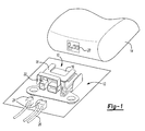
- FIG. 1 is a general perspective view an electronic control unit mounted in a vehicle passenger compartment;
- FIG. 2 is a side view of the block diagram of the electronic control unit.
- FIG. 3 is a top view of the block diagram of the electronic control unit.
- FIG. 1 illustrates a general perspective view of an electronic control unit assembly 10 .
- the electronic control unit assembly 10 is typically mounted within a vehicle passenger compartment 12 under an electrically or manually adjustable vehicle seat 14 . It should be understood that other mounting locations will benefit from the present invention.
- the electronic control unit assembly 10 includes an electronic control unit (ECU) 16 and a housing 18 .
- ECU electronice control unit
- housing is to be construed broadly and shall not be limited to a box-like enclosure.
- the ECU 16 is a box-like structure which contains the electronic controls such as a microprocessor and memory.
- the ECU 16 communicates with controls (illustrated schematically at 20 ) or the like to operate air bags and similar restraint devices. It should be understood that vehicle systems other than a seat will benefit from the present invention.
- the ECU 16 includes a connector interface 22 which extends from one side of the ECU 16 .
- the connector interface 22 is preferably oriented toward a driver side of the vehicle, however, other orientations will also benefit from the present invention.
- the connector interface 22 removably receives a plurality of connectors 24 which extends from a wire harness 26 to provide communication between the ECU 16 and the vehicle system 14 .
- the connectors 24 are typically manufactured of a plastic material or the like and may be more susceptible to damage than the ECU 16 .
- the housing 18 is preferably a plate-like member manufactured from a metallic material such as steel.
- the housing 18 include a housing first portion 28 and a housing second portion 30 .
- An intermediate portion 32 bridges the housing first portion 28 and the housing second portion 30 .
- the housing first portion 28 mounts to a relatively planar surface 35 of the ECU 16 .
- the planar surface 35 is preferably an upper surface of the ECU 16 located opposite a vehicle passenger compartment floor 33 .
- a plurality of fasteners 34 pass through apertures 36 (also illustrated in FIG. 3) within the housing first portion 28 and are threaded into the ECU 16 to fix the housing 18 to the ECU 16 .
- the housing second portion 30 extends from the housing first portion 28 and at least partially covers the connector interface 22 and the plurality of connectors 24 . That is, the housing second portion 30 extends from the housing first portion 28 in a substantially cantilevered manner to protect the connector interface 22 and the plurality of connectors 24 from damage.
- the housing second portion 30 is displaced further away from the ECU 16 relative the housing first portion 28 .
- the housing second portion 30 extends a predetermined distance d away from the connectors 24 .
- the predetermined distance d is defined by the distance necessary for an operator to release the plurality of connectors 24 from the connector interface 22 . It should be understood that as different connectors 24 require different disassembly techniques, the predetermined distance d will primarily be determined by the disassembly technique. This predetermined distance is commonly referred to as a “finger clearance” which is necessary for an operator to reach each connector 24 and release it from the connector interface 22 . Although well protected, the connectors 24 are readily accessible.
- the housing 18 housing first portion 28 includes an opening 38 . Opening 38 is preferably arranged to allow an ECU identification label 40 to be visible. The housing 18 will therefore not obscure the label 40 but will still meet strength and resonance requirements for protection of the connectors 24 .
Abstract
The electronic control unit assembly (10) includes an electronic control unit (16) and a housing (18). The housing (18) include a housing first portion (28) and a housing second portion (30). The housing first portion (28) mounts to a relatively planar surface of the ECU (16). The housing second portion (30) extends from the housing first portion in a cantilever manner to at least partially cover the connector interface (22) and the plurality of connectors (24) to provide protection therefore.
Description
The present application claims priority to U.S. Provisional Patent Application Ser. No. 60/318,920, filed Sep. 13, 2001.
The present invention relates to an electronic control unit, and more particularly to a housing for an electronic control unit to protect connectors which extend therefrom.
A vehicle electronic control unit (ECU) operates to control a vehicle system such as airbag and restraints. In some instances, the ECU must be mounted in an exposed position within the vehicle passenger compartment such as under the vehicle seat. A plurality of connectors typically extend from the ECU. The connectors connect the ECU to the vehicle system which are controlled by the ECU. The exposed position may subject the ECU to damage from external forces which may disconnect or damage the exposed connectors.
Although the connectors must be protected, the connectors must also be accessible for maintenance. Specified “finger clearances” must be provided to allow ready access to the connectors. These competing priorities of protection and accessibility create mounting difficulties for the ECU. Moreover, as not all mounting locations require the same level of protection, it is desirable to avoid directly incorporating relatively expensive protection to the base ECU design.
Accordingly, it is desirable to provide an inexpensive ECU housing which protects the exposed connectors while allowing access to the connectors for maintenance. It is further desirable to removably mount the housing such that protection can be provided for only those ECU mounting positions which expose the ECU.
The electronic control unit assembly according to the present invention includes an electronic control unit (ECU) and a housing. The ECU is a box-like structure which contains the electronic controls such as a microprocessor and memory. The ECU includes a connector interface which extends from the ECU. The connector interface removably receives a plurality of connectors which extend from a wire harness to provide communication between the ECU and a vehicle system.
The housing includes a housing first portion and a housing second portion. The housing first portion mounts to a relatively planar surface of the ECU. A plurality of fasteners pass through apertures within the housing first portion and are threaded into the ECU to fix the housing to the ECU. The housing second portion extends from the housing first portion in a cantilever manner to at least partially cover the connector interface and the plurality of connectors to provide protection therefore.
The present invention therefore provides an inexpensive ECU housing which protects the exposed connectors yet allows access to the connectors for maintenance. It also gives the option of not using the protection at all. The main ECU has the external fastener holes pre-cast. Then the “bracket” can be used in only certain packaging locations.
The various features and advantages of this invention will become apparent to those skilled in the art from the following detailed description of the currently preferred embodiment. The drawings that accompany the detailed description can be briefly described as follows:
FIG. 1 is a general perspective view an electronic control unit mounted in a vehicle passenger compartment;
FIG. 2 is a side view of the block diagram of the electronic control unit; and
FIG. 3 is a top view of the block diagram of the electronic control unit.
FIG. 1 illustrates a general perspective view of an electronic control unit assembly 10. The electronic control unit assembly 10 is typically mounted within a vehicle passenger compartment 12 under an electrically or manually adjustable vehicle seat 14. It should be understood that other mounting locations will benefit from the present invention.
The electronic control unit assembly 10 includes an electronic control unit (ECU) 16 and a housing 18. It should be understood that the term “housing” is to be construed broadly and shall not be limited to a box-like enclosure.
The ECU 16 is a box-like structure which contains the electronic controls such as a microprocessor and memory. The ECU 16 communicates with controls (illustrated schematically at 20) or the like to operate air bags and similar restraint devices. It should be understood that vehicle systems other than a seat will benefit from the present invention. The ECU 16 includes a connector interface 22 which extends from one side of the ECU 16. The connector interface 22 is preferably oriented toward a driver side of the vehicle, however, other orientations will also benefit from the present invention. The connector interface 22 removably receives a plurality of connectors 24 which extends from a wire harness 26 to provide communication between the ECU 16 and the vehicle system 14. The connectors 24 are typically manufactured of a plastic material or the like and may be more susceptible to damage than the ECU 16.
Referring to FIG. 2, the housing 18 is preferably a plate-like member manufactured from a metallic material such as steel. The housing 18 include a housing first portion 28 and a housing second portion 30. An intermediate portion 32 bridges the housing first portion 28 and the housing second portion 30.
The housing first portion 28 mounts to a relatively planar surface 35 of the ECU 16. The planar surface 35 is preferably an upper surface of the ECU 16 located opposite a vehicle passenger compartment floor 33. A plurality of fasteners 34 pass through apertures 36 (also illustrated in FIG. 3) within the housing first portion 28 and are threaded into the ECU 16 to fix the housing 18 to the ECU 16.
The housing second portion 30 extends from the housing first portion 28 and at least partially covers the connector interface 22 and the plurality of connectors 24. That is, the housing second portion 30 extends from the housing first portion 28 in a substantially cantilevered manner to protect the connector interface 22 and the plurality of connectors 24 from damage.
The housing second portion 30 is displaced further away from the ECU 16 relative the housing first portion 28. Preferably, the housing second portion 30 extends a predetermined distance d away from the connectors 24. The predetermined distance d is defined by the distance necessary for an operator to release the plurality of connectors 24 from the connector interface 22. It should be understood that as different connectors 24 require different disassembly techniques, the predetermined distance d will primarily be determined by the disassembly technique. This predetermined distance is commonly referred to as a “finger clearance” which is necessary for an operator to reach each connector 24 and release it from the connector interface 22. Although well protected, the connectors 24 are readily accessible.
Referring to FIG. 3, the housing 18 housing first portion 28 includes an opening 38. Opening 38 is preferably arranged to allow an ECU identification label 40 to be visible. The housing 18 will therefore not obscure the label 40 but will still meet strength and resonance requirements for protection of the connectors 24.
The foregoing description is exemplary rather than defined by the limitations within. Many modifications and variations of the present invention are possible in light of the above teachings. The preferred embodiments of this invention have been disclosed, however, one of ordinary skill in the art would recognize that certain modifications would come within the scope of this invention. It is, therefore, to be understood that within the scope of the appended claims, the invention may be practiced otherwise than as specifically described. For that reason the following claims should be studied to determine the true scope and content of this invention.
Claims (11)
1. An electronic control unit assembly comprising:
an electronic control unit;
a connector interface extending from said electronic control unit; and
a housing comprising a housing first portion and a housing second portion, said housing first portion mountable to said electronic control unit, and said housing second portion displaced from said housing first portion to at least partially cover said connector interface.
2. The electronic control unit assembly as recited in claim 1 , wherein said housing first portion comprises an opening such that at least a portion of said electronic control unit is visible therethrough.
3. The electronic control unit assembly as recited in claim 1 , wherein said housing second portion is offset and substantially parallel to said housing first portion.
4. The electronic control unit assembly as recited in claim 1 , wherein said housing second portion is displaced further away from said electronic control unit than said housing first portion.
5. The electronic control unit assembly as recited in claim 1 , wherein said housing first portion comprises a plurality of apertures to receive fasteners which engage said electronic control unit.
6. The electronic control unit assembly as recited in claim 1 , wherein said housing comprises a plate.
7. An electronic control unit assembly comprising:
an electronic control unit defining a relatively planar surface;
a connector interface extending from said electronic control unit; and
a housing comprising a housing first portion and a housing second portion, said housing first portion mountable to said planar surface, and said housing second portion at least partially covering said connector interface, said housing second portion offset and substantially parallel to said housing first portion.
8. The electronic control unit assembly as recited in claim 7 , wherein said housing first portion comprises an opening such that at least a portion of said relatively planar surface is visible therethrough.
9. The electronic control unit assembly as recited in claim 7 , wherein said housing comprises a plate.
10. The electronic control unit assembly as recited in claim 9 , wherein said housing second portion is displaced further away from said relatively planar surface than said housing first portion.
11. The electronic control unit assembly as recited in claim 9 , wherein said housing second portion is offset from said housing first portion defines a predetermined clearance between said connector interface and said housing second portion.
Priority Applications (1)
| Application Number | Priority Date | Filing Date | Title |
|---|---|---|---|
| US10/206,573 US6669505B2 (en) | 2001-09-13 | 2002-07-26 | Vehicle electronic control units |
Applications Claiming Priority (2)
| Application Number | Priority Date | Filing Date | Title |
|---|---|---|---|
| US31892001P | 2001-09-13 | 2001-09-13 | |
| US10/206,573 US6669505B2 (en) | 2001-09-13 | 2002-07-26 | Vehicle electronic control units |
Publications (2)
| Publication Number | Publication Date |
|---|---|
| US20030049947A1 US20030049947A1 (en) | 2003-03-13 |
| US6669505B2 true US6669505B2 (en) | 2003-12-30 |
Family
ID=23240126
Family Applications (1)
| Application Number | Title | Priority Date | Filing Date |
|---|---|---|---|
| US10/206,573 Expired - Fee Related US6669505B2 (en) | 2001-09-13 | 2002-07-26 | Vehicle electronic control units |
Country Status (2)
| Country | Link |
|---|---|
| US (1) | US6669505B2 (en) |
| WO (1) | WO2003022637A1 (en) |
Cited By (6)
| Publication number | Priority date | Publication date | Assignee | Title |
|---|---|---|---|---|
| US20030186115A1 (en) * | 2002-03-29 | 2003-10-02 | Honda Giken Kogyo Kabushiki Kaisha | Installation structure of battery unit |
| US20040035224A1 (en) * | 2002-08-21 | 2004-02-26 | Takata Corporation | Seat load measuring apparatus |
| US20100078918A1 (en) * | 2008-09-30 | 2010-04-01 | Fujitsu Ten Limited | Housing fixing structure |
| US20100253188A1 (en) * | 2009-04-03 | 2010-10-07 | Fujitsu Ten Limited | Housing structure for in-vehicle electronic device |
| US20140120749A1 (en) * | 2012-10-30 | 2014-05-01 | Continental Automotive Gmbh | Printed circuit board assembly for a control device, control device for a motor vehicle and signal processing arrangement |
| WO2016189523A1 (en) * | 2015-05-28 | 2016-12-01 | Daniel Cohen | Tamper resistant case |
Families Citing this family (1)
| Publication number | Priority date | Publication date | Assignee | Title |
|---|---|---|---|---|
| FR2987012B1 (en) * | 2012-02-20 | 2014-11-28 | Peugeot Citroen Automobiles Sa | MULTI-FUNCTION PROTECTION DEVICE FOR AN INFLATABLE BAG (S) CONTROL UNIT (S) OF A VEHICLE |
Citations (18)
| Publication number | Priority date | Publication date | Assignee | Title |
|---|---|---|---|---|
| US4047242A (en) * | 1975-07-05 | 1977-09-06 | Robert Bosch G.M.B.H. | Compact electronic control and power unit structure |
| US4409641A (en) * | 1980-06-02 | 1983-10-11 | Robert Bosch Gmbh | Environmentally protected electronic network structure and housing combination |
| WO1994029145A1 (en) | 1993-06-09 | 1994-12-22 | United Technologies Automotive, Inc. | Hybrid junction box |
| FR2715247A1 (en) | 1994-01-14 | 1995-07-21 | Sylea | Protection casing for high current lead inside car engine compartment |
| US5671122A (en) * | 1992-09-24 | 1997-09-23 | Siemens Akitiengesellschaft | Electronic control unit |
| US5777850A (en) * | 1993-06-26 | 1998-07-07 | Robert Bosch Gmbh | Built-in control device for actuating loads with conductor foil-covered printed circuit board |
| EP0999098A2 (en) | 1998-11-04 | 2000-05-10 | Adam Opel Ag | Motor vehicle with fuse box |
| US6108202A (en) * | 1996-07-03 | 2000-08-22 | Sumitomo Wiring Systems, Ltd. | Electric connection box |
| US6155856A (en) | 1998-11-24 | 2000-12-05 | Sumitomo Electric Industries, Ltd. | Electronic control unit with electrical connector |
| US6213096B1 (en) | 1998-03-25 | 2001-04-10 | Sanshin Kogyo Kabushiki Kaisha | Fuel supply for direct injected engine |
| US6302707B1 (en) * | 1998-04-16 | 2001-10-16 | Siemens Aktiengesellschaft | Electric circuit provided with a plug-in connector, in particular a control device for motor vehicles |
| US6302190B1 (en) | 1998-06-30 | 2001-10-16 | Cummins Engine Company Ltd. | Cooling an engine control unit |
| US6315604B1 (en) * | 2000-09-28 | 2001-11-13 | Monster Cable Products, Inc. | Power center assembly having electrical connection-protection and optional detachable surface mount |
| US6318329B1 (en) | 1998-07-23 | 2001-11-20 | Sanshin Kogyo Kabushiki Kaisha | Vibration damping mount for engine control components |
| US6434013B2 (en) * | 2000-02-24 | 2002-08-13 | Keihin Corporation | Electronic circuit board case |
| US6478614B1 (en) * | 2001-04-20 | 2002-11-12 | De'longhi S.P.A. | Easy-detach electrical connector for kitchen appliance |
| US6552911B1 (en) * | 1999-05-12 | 2003-04-22 | Robert Bosch Gmbh | Electrical device |
| US6560115B1 (en) * | 1999-05-14 | 2003-05-06 | Fujitsu Ten Limited | Combination structure of electronic equipment |
-
2002
- 2002-07-26 US US10/206,573 patent/US6669505B2/en not_active Expired - Fee Related
- 2002-09-12 WO PCT/US2002/029168 patent/WO2003022637A1/en active Application Filing
Patent Citations (18)
| Publication number | Priority date | Publication date | Assignee | Title |
|---|---|---|---|---|
| US4047242A (en) * | 1975-07-05 | 1977-09-06 | Robert Bosch G.M.B.H. | Compact electronic control and power unit structure |
| US4409641A (en) * | 1980-06-02 | 1983-10-11 | Robert Bosch Gmbh | Environmentally protected electronic network structure and housing combination |
| US5671122A (en) * | 1992-09-24 | 1997-09-23 | Siemens Akitiengesellschaft | Electronic control unit |
| WO1994029145A1 (en) | 1993-06-09 | 1994-12-22 | United Technologies Automotive, Inc. | Hybrid junction box |
| US5777850A (en) * | 1993-06-26 | 1998-07-07 | Robert Bosch Gmbh | Built-in control device for actuating loads with conductor foil-covered printed circuit board |
| FR2715247A1 (en) | 1994-01-14 | 1995-07-21 | Sylea | Protection casing for high current lead inside car engine compartment |
| US6108202A (en) * | 1996-07-03 | 2000-08-22 | Sumitomo Wiring Systems, Ltd. | Electric connection box |
| US6213096B1 (en) | 1998-03-25 | 2001-04-10 | Sanshin Kogyo Kabushiki Kaisha | Fuel supply for direct injected engine |
| US6302707B1 (en) * | 1998-04-16 | 2001-10-16 | Siemens Aktiengesellschaft | Electric circuit provided with a plug-in connector, in particular a control device for motor vehicles |
| US6302190B1 (en) | 1998-06-30 | 2001-10-16 | Cummins Engine Company Ltd. | Cooling an engine control unit |
| US6318329B1 (en) | 1998-07-23 | 2001-11-20 | Sanshin Kogyo Kabushiki Kaisha | Vibration damping mount for engine control components |
| EP0999098A2 (en) | 1998-11-04 | 2000-05-10 | Adam Opel Ag | Motor vehicle with fuse box |
| US6155856A (en) | 1998-11-24 | 2000-12-05 | Sumitomo Electric Industries, Ltd. | Electronic control unit with electrical connector |
| US6552911B1 (en) * | 1999-05-12 | 2003-04-22 | Robert Bosch Gmbh | Electrical device |
| US6560115B1 (en) * | 1999-05-14 | 2003-05-06 | Fujitsu Ten Limited | Combination structure of electronic equipment |
| US6434013B2 (en) * | 2000-02-24 | 2002-08-13 | Keihin Corporation | Electronic circuit board case |
| US6315604B1 (en) * | 2000-09-28 | 2001-11-13 | Monster Cable Products, Inc. | Power center assembly having electrical connection-protection and optional detachable surface mount |
| US6478614B1 (en) * | 2001-04-20 | 2002-11-12 | De'longhi S.P.A. | Easy-detach electrical connector for kitchen appliance |
Cited By (12)
| Publication number | Priority date | Publication date | Assignee | Title |
|---|---|---|---|---|
| US20030186115A1 (en) * | 2002-03-29 | 2003-10-02 | Honda Giken Kogyo Kabushiki Kaisha | Installation structure of battery unit |
| US7004274B2 (en) * | 2002-03-29 | 2006-02-28 | Honda Giken Kogyo Kabushiki Kaisha | Installation structure of battery unit |
| US20040035224A1 (en) * | 2002-08-21 | 2004-02-26 | Takata Corporation | Seat load measuring apparatus |
| US20070209451A1 (en) * | 2002-08-21 | 2007-09-13 | Takata Corporation | Seat load measuring apparatus |
| US7399932B2 (en) | 2002-08-21 | 2008-07-15 | Takata Corporation | Seat load measuring apparatus |
| US20100078918A1 (en) * | 2008-09-30 | 2010-04-01 | Fujitsu Ten Limited | Housing fixing structure |
| US8096576B2 (en) * | 2008-09-30 | 2012-01-17 | Fujitsu Ten Limited | Housing fixing structure |
| US20100253188A1 (en) * | 2009-04-03 | 2010-10-07 | Fujitsu Ten Limited | Housing structure for in-vehicle electronic device |
| US8414013B2 (en) * | 2009-04-03 | 2013-04-09 | Fujitsu Ten Limited | Housing structure for in-vehicle electronic device |
| US20140120749A1 (en) * | 2012-10-30 | 2014-05-01 | Continental Automotive Gmbh | Printed circuit board assembly for a control device, control device for a motor vehicle and signal processing arrangement |
| US9065222B2 (en) * | 2012-10-30 | 2015-06-23 | Continental Automotive Gmbh | Printed circuit board assembly for a control device, control device for a motor vehicle and signal processing arrangement |
| WO2016189523A1 (en) * | 2015-05-28 | 2016-12-01 | Daniel Cohen | Tamper resistant case |
Also Published As
| Publication number | Publication date |
|---|---|
| US20030049947A1 (en) | 2003-03-13 |
| WO2003022637A1 (en) | 2003-03-20 |
Similar Documents
| Publication | Publication Date | Title |
|---|---|---|
| US7424347B2 (en) | Motion sensors integrated within an electro-hydraulic control unit | |
| US20090212541A1 (en) | Assembly with an instrument panel for a motor vehicle and a knee airbag | |
| US6669505B2 (en) | Vehicle electronic control units | |
| US10864880B2 (en) | Knee airbag module housing with securement element mounting features | |
| EP3566910B1 (en) | Wire harness, component module for wire harness, and vehicle component | |
| KR20180000305A (en) | Electrical distribution center | |
| CN109937616B (en) | Occupant protection control device | |
| US6943292B2 (en) | Printed circuit board stiffener | |
| EP0809326A2 (en) | Electrical connection box | |
| CN113677556A (en) | Device, system and vehicle for installing traction battery | |
| KR20040034707A (en) | Sensor device and method for arranging a sensor device on a mounting plate | |
| US7331414B2 (en) | Protective structure for an electrical circuit device | |
| US20050242554A1 (en) | Seat load measuring device and occupant protection system using the same | |
| US7294783B2 (en) | Mounting component for a motor vehicle and method for installing a vehicle electrical system for a motor vehicle | |
| KR0177480B1 (en) | Vehicle airbag ECU mounting bracket | |
| KR0133780Y1 (en) | Ecu support bracket in an automobile | |
| JP7424900B2 (en) | vehicle control system | |
| KR101372551B1 (en) | Control board of DEVICE | |
| US20210245691A1 (en) | Airbag controller for vehicle | |
| CN217656856U (en) | Instrument fuse box cover plate, instrument fuse box and vehicle | |
| JPH06144181A (en) | Anti-lock brake system | |
| JP2011135696A (en) | Installation structure of electric junction box | |
| US6659787B2 (en) | Attachment portion structure of connector | |
| US20040174001A1 (en) | Generator carrier for a driver's gas bag module and function module for a steering wheel of a motor vehicle | |
| KR100503317B1 (en) | Airbab Control Unit Housing of car |
Legal Events
| Date | Code | Title | Description |
|---|---|---|---|
| AS | Assignment |
Owner name: SIEMENS VDO AUTOMOTIVE CORPORATION, MICHIGAN Free format text: ASSIGNMENT OF ASSIGNORS INTEREST;ASSIGNOR:WISNIEWSKI, ANDREW;REEL/FRAME:013156/0326 Effective date: 20020725 |
|
| REMI | Maintenance fee reminder mailed | ||
| LAPS | Lapse for failure to pay maintenance fees | ||
| STCH | Information on status: patent discontinuation |
Free format text: PATENT EXPIRED DUE TO NONPAYMENT OF MAINTENANCE FEES UNDER 37 CFR 1.362 |
|
| FP | Lapsed due to failure to pay maintenance fee |
Effective date: 20071230 |