EP1391648A1 - Fill valve assembly - Google Patents
Fill valve assembly Download PDFInfo
- Publication number
- EP1391648A1 EP1391648A1 EP20030253747 EP03253747A EP1391648A1 EP 1391648 A1 EP1391648 A1 EP 1391648A1 EP 20030253747 EP20030253747 EP 20030253747 EP 03253747 A EP03253747 A EP 03253747A EP 1391648 A1 EP1391648 A1 EP 1391648A1
- Authority
- EP
- European Patent Office
- Prior art keywords
- fill
- valve
- axially slidable
- valve seat
- float
- Prior art date
- Legal status (The legal status is an assumption and is not a legal conclusion. Google has not performed a legal analysis and makes no representation as to the accuracy of the status listed.)
- Granted
Links
- 239000012530 fluid Substances 0.000 claims abstract description 48
- 238000007789 sealing Methods 0.000 claims abstract description 22
- 238000011144 upstream manufacturing Methods 0.000 claims abstract description 3
- 230000008878 coupling Effects 0.000 description 5
- 238000010168 coupling process Methods 0.000 description 5
- 238000005859 coupling reaction Methods 0.000 description 5
- 239000007788 liquid Substances 0.000 description 4
- 239000007921 spray Substances 0.000 description 4
- 230000006835 compression Effects 0.000 description 3
- 238000007906 compression Methods 0.000 description 3
- 230000007423 decrease Effects 0.000 description 2
- 230000009467 reduction Effects 0.000 description 2
- 230000004044 response Effects 0.000 description 2
- 230000009471 action Effects 0.000 description 1
- 230000000712 assembly Effects 0.000 description 1
- 238000000429 assembly Methods 0.000 description 1
- 238000006073 displacement reaction Methods 0.000 description 1
- 230000004048 modification Effects 0.000 description 1
- 238000012986 modification Methods 0.000 description 1
Images






Classifications
-
- F—MECHANICAL ENGINEERING; LIGHTING; HEATING; WEAPONS; BLASTING
- F16—ENGINEERING ELEMENTS AND UNITS; GENERAL MEASURES FOR PRODUCING AND MAINTAINING EFFECTIVE FUNCTIONING OF MACHINES OR INSTALLATIONS; THERMAL INSULATION IN GENERAL
- F16K—VALVES; TAPS; COCKS; ACTUATING-FLOATS; DEVICES FOR VENTING OR AERATING
- F16K31/00—Actuating devices; Operating means; Releasing devices
- F16K31/12—Actuating devices; Operating means; Releasing devices actuated by fluid
- F16K31/18—Actuating devices; Operating means; Releasing devices actuated by fluid actuated by a float
- F16K31/20—Actuating devices; Operating means; Releasing devices actuated by fluid actuated by a float actuating a lift valve
- F16K31/24—Actuating devices; Operating means; Releasing devices actuated by fluid actuated by a float actuating a lift valve with a transmission with parts linked together from a single float to a single valve
- F16K31/26—Actuating devices; Operating means; Releasing devices actuated by fluid actuated by a float actuating a lift valve with a transmission with parts linked together from a single float to a single valve with the valve guided for rectilinear movement and the float attached to a pivoted arm
-
- F—MECHANICAL ENGINEERING; LIGHTING; HEATING; WEAPONS; BLASTING
- F16—ENGINEERING ELEMENTS AND UNITS; GENERAL MEASURES FOR PRODUCING AND MAINTAINING EFFECTIVE FUNCTIONING OF MACHINES OR INSTALLATIONS; THERMAL INSULATION IN GENERAL
- F16K—VALVES; TAPS; COCKS; ACTUATING-FLOATS; DEVICES FOR VENTING OR AERATING
- F16K1/00—Lift valves or globe valves, i.e. cut-off apparatus with closure members having at least a component of their opening and closing motion perpendicular to the closing faces
- F16K1/32—Details
- F16K1/34—Cutting-off parts, e.g. valve members, seats
- F16K1/36—Valve members
- F16K1/38—Valve members of conical shape
- F16K1/385—Valve members of conical shape contacting in the closed position, over a substantial axial length, a seat surface having the same inclination
-
- Y—GENERAL TAGGING OF NEW TECHNOLOGICAL DEVELOPMENTS; GENERAL TAGGING OF CROSS-SECTIONAL TECHNOLOGIES SPANNING OVER SEVERAL SECTIONS OF THE IPC; TECHNICAL SUBJECTS COVERED BY FORMER USPC CROSS-REFERENCE ART COLLECTIONS [XRACs] AND DIGESTS
- Y10—TECHNICAL SUBJECTS COVERED BY FORMER USPC
- Y10T—TECHNICAL SUBJECTS COVERED BY FORMER US CLASSIFICATION
- Y10T137/00—Fluid handling
- Y10T137/7287—Liquid level responsive or maintaining systems
- Y10T137/7358—By float controlled valve
- Y10T137/7439—Float arm operated valve
- Y10T137/7446—With flow guide or restrictor
-
- Y—GENERAL TAGGING OF NEW TECHNOLOGICAL DEVELOPMENTS; GENERAL TAGGING OF CROSS-SECTIONAL TECHNOLOGIES SPANNING OVER SEVERAL SECTIONS OF THE IPC; TECHNICAL SUBJECTS COVERED BY FORMER USPC CROSS-REFERENCE ART COLLECTIONS [XRACs] AND DIGESTS
- Y10—TECHNICAL SUBJECTS COVERED BY FORMER USPC
- Y10T—TECHNICAL SUBJECTS COVERED BY FORMER US CLASSIFICATION
- Y10T137/00—Fluid handling
- Y10T137/7287—Liquid level responsive or maintaining systems
- Y10T137/7358—By float controlled valve
- Y10T137/7439—Float arm operated valve
- Y10T137/7465—Assembly mounted on and having reciprocating valve element coaxial with inlet pipe
-
- Y—GENERAL TAGGING OF NEW TECHNOLOGICAL DEVELOPMENTS; GENERAL TAGGING OF CROSS-SECTIONAL TECHNOLOGIES SPANNING OVER SEVERAL SECTIONS OF THE IPC; TECHNICAL SUBJECTS COVERED BY FORMER USPC CROSS-REFERENCE ART COLLECTIONS [XRACs] AND DIGESTS
- Y10—TECHNICAL SUBJECTS COVERED BY FORMER USPC
- Y10T—TECHNICAL SUBJECTS COVERED BY FORMER US CLASSIFICATION
- Y10T137/00—Fluid handling
- Y10T137/7287—Liquid level responsive or maintaining systems
- Y10T137/7358—By float controlled valve
- Y10T137/7439—Float arm operated valve
- Y10T137/7478—With interposed cam, gear or threaded connection
Definitions
- the present invention relates to fill valve assemblies generally.
- the present invention seeks to provide an improved fill valve assembly.
- a fill valve assembly including a valve body extending along a longitudinal axis and defining a fluid inlet, a valve seat and at least one fluid outlet, an axially slidable valve element arranged for axially slidable movement, along the longitudinal axis, into and out of sealing engagement with the valve seat, the axially slidable valve element defining a first upstream conical surface having a first surface area and a second downstream conical surface having a second surface area, greater than the first surface area, and a fill sensor operative below a predetermined fill threshold to prevent the axially slidable valve element from establishing sealing engagement with the valve seal.
- the at least one fluid outlet comprises a pair of oppositely directed fluid outlets arranged to direct fluid at an angle of preferably 45 degrees below the horizontal axis.
- a fill valve assembly including a valve body extending along a longitudinal axis and defining a fluid inlet, a valve seat and a pair of oppositely directed fluid outlets arranged to direct fluid at an angle of preferably 45 degrees below the horizontal axis, an axially slidable valve element arranged for axially slidable movement along the longitudinal axis, into and out of sealing engagement with the valve seat, and a fill sensor operative below a predetermined fill threshold to prevent the axially slidable valve element from establishing sealing engagement with the valve seat.
- the axially slidable valve element is arranged for axially slidable movement along the longitudinal axis, along first and second guides, into and out of sealing engagement with the valve seat.
- a fill valve assembly including a valve body extending along a longitudinal axis and defining a fluid inlet, a valve seat and at least one fluid outlet, an axially slidable valve element arranged for axially slidable movement along the longitudinal axis, along first and second guides, into and out of sealing engagement with the valve seat, and a fill sensor operative below a predetermined fill threshold to prevent the axially slidable valve element from establishing sealing engagement with the valve seat.
- the at least one fluid outlet comprises a pair of oppositely directed fluid outlets arranged to direct fluid at an angle of preferably 45 degrees below the horizontal axis.
- the first guide comprises a plurality of guide fingers disposed above the valve seat.
- the second guide comprises a guide bore defined by the valve body below the valve seat.
- the fill sensor comprises a float assembly operative within a predetermined range of float orientations relative to the longitudinal axis to prevent the axially slidable valve element from establishing sealing engagement with the valve seat.
- the float assembly includes a hollow float element having an opening arranged at a bottom, outwardly extending location thereon.
- Fig. 1 is a simplified exploded view and sectional illustration of a fill valve assembly constructed and operative in accordance with a preferred embodiment of the present invention
- Figs. 2A, 2B and 2C are simplified pictorial illustrations of the fill valve assembly of Fig. I in three different operative orientations;
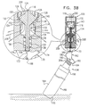
- Figs 3A, 3B, 3C, 3D and 3E are simplified partially sectional, partially pictorial illustrations of the fill valve assembly of Fig. 1 in five different operative orientations;
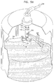
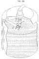
- Figs. 4A, 4B and 4C are simplified pictorial illustrations of the fill valve assembly of Fig. 1 in three different operative orientations during filling;
- Figs. 5A, 5B and 5C are simplified pictorial illustrations of a variation of the fill valve assembly of Fig. 1 in three different operative orientations during filling;
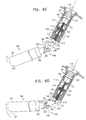
- Figs. 6A, 6B, 6C, 6D and 6E are simplified pictorial illustrations of the fill valve assembly of Fig. 1 in five different operative orientations during filling at an angle.
- Fig. 1 is a simplified exploded view and sectional illustration of a fill valve assembly constructed and operative in accordance with a preferred embodiment of the present invention.
- a fill valve assembly preferably comprising an internally threaded coupler 100 which is adapted for connection to a fill pipe (not shown).
- Coupler 100 as shown in Fig. 1, preferably includes a first generally cylindrical portion 102 having a relatively large inner and outer diameter, which is integrally formed with a second generally cylindrical portion 104, having inner and outer diameters which are small than those of portion 102.
- Cylindrical portion 102 preferably is formed with threading along its inner surface 106, while cylindrical portion 104 preferably is formed with threading along its outer surface 108.
- a guide 110 preferably formed by a plurality of guide fingers 112 which extend inwardly with respect to cylindrical portion 104, thereby to define a guide for axial motion of an axially slidable valve element 114 along an axis 116.
- Axially slidable valve element 114 is preferably a rotationally symmetric integrally formed element and preferably includes top and bottom shaft portions 118 and 120, the top shaft portion 118 being arranged for slidable motion relative to guide 110. Disposed below top shaft portion 118 and separated therefrom by a shoulder 122 is a first intermediate shaft portion 124 having an outer diameter slightly greater than that of top shaft portion 118.
- Intermediate shaft portion 124 terminates in a first generally conical portion 126, which preferably defines a 120 degree truncated cone. Disposed below conical portion 126 is a relatively narrow circularly cylindrical band 128 from which depends a second generally conical portion 130, which preferably defines a 90 degree truncated cone and terminates in a second intermediate shaft portion 132.
- Intermediate shaft portion 132 preferably terminates in a spring seat 134, which is typically of truncated conical configuration and defines a generally flat spring seat surface 136 from which extends the bottom shaft portion 120.
- a compression spring 138 is arranged to be disposed about bottom shaft portion 120.
- a valve body 140 is arranged for threaded attachment to coupler 100.
- the valve body preferably is of generally circularly cylindrical configuration and has first and second generally oppositely facing outlet apertures 142 and 144 formed therein. Integrally formed with the valve body and depending therefrom are a pair of mutually aligned mounting lugs 146, preferably formed with coaxial apertures 148.
- valve body 140 preferably includes a central bore 150, which is preferably formed with internal threading at the top thereof for threaded engagement with corresponding threading on the outer surface 108 of coupler 100.
- Central bore 150 preferably leads to a generally conical valve seat portion 152, which matches the conical configuration of second truncated conical surface 130 of slidable valve element 114 and thus defines an angle of 90 degrees.
- Below valve seat portion 152 is an intermediate bore 154, having a diameter which is less than that of central bore 150 and communicating with outlet apertures 142 and 144.
- Intermediate bore 154 Disposed below intermediate bore 154 is a spring seat defining bore 156, having an diameter which is less than that of intermediate bore 154.
- spring seat defining bore 156 Disposed below spring seat defining bore 156 is a guide bore 158 which serves as a guide for bottom shaft portion 120 of slidable valve element 114 and has a diameter which is less than that of spring seat defining bore 156.
- a shoulder 160 defined by the intersection of bores 154 and 156 defines a spring seat for spring 138.
- a cam 162 is pivotably attached to valve body 140 by means of a pin 164 which extends along a pivot axis 166 through coaxial apertures 148 of mutually aligned mounting lugs 146 and through a first aperture 168 formed in cam 162.
- Cam 162 is preferably an integrally formed element comprising an asymmetrical upper portion 170 lying above aperture 168 and including a bottom shaft engagement surface 172 and a valve body engagement surface 174 adjacent to bottom shaft engagement surface 172 and spaced therefrom.
- Integrally formed with upper portion 170 is an intermediate portion 176 extending generally from aperture 168 down to a second aperture 178 and defining a first float engagement surface 180. Integrally formed with intermediate portion 176 is a bottom portion 182, extending downwardly from aperture 178 and defining a second float engagement surface 184.
- a float assembly 186 is pivotably mounted onto cam 162 by means of a pin 188 extending through aperture 178 and through coaxial apertures 190 formed in float assembly 186 along a pivot axis 192.
- Float assembly 186 preferably comprises a generally hollow cylindrical portion 194, having an opening 195 at a bottom outwardly extending location thereon.
- Cylindrical portion 194 is rigidly coupled to a float coupling element 196, which is pivotably mounted via apertures 190 formed therein to cam 162.
- the float coupling element 196 preferably includes a first generally cylindrical portion 198, which is sealed to cylindrical portion 194. Integrally formed with first cylindrical portion 198 is a second cylindrical portion 200 of smaller diameter that first cylindrical portion 198 and having formed therein a slit 202 which defines a bifurcated mounting including apertures 190 and a cam engagement surface 204.
- FIG. 2A shows an initial fill operative orientation, wherein float assembly 186 is in its most downward facing orientation and hollow cylindrical portion 194 is filled with air.
- float assembly 186 is in the orientation shown in Fig. 2A, fluid supplied under pressure to valve body 140, as indicated by arrows 206 is allowed to exit the valve body through oppositely facing outlet apertures 142 and 144 formed therein, as indicated by arrows 208.
- Fig. 2B illustrates an intermediate operative orientation wherein the float assembly 186 is partially raised by the level of liquid (not shown) lying therebelow.
- the orientation of opening 195 in cylindrical portion 194 ensures that the cylindrical portion remains generally filled with air. It is seen that also when float assembly 186 is in the intermediate orientation shown in Fig. 2B, fluid supplied under pressure to valve body 140, as indicated by arrows 206 is allowed to exit the valve body through oppositely facing outlet apertures 142 and 144 formed therein, as indicated by arrows 208.
- Fig. 2C illustrates a full raised operative orientation wherein the float assembly 186 is fully raised by the level of liquid (not shown) lying therebelow.
- the orientation of opening 195 in cylindrical portion 194 ensures that the cylindrical portion remains generally filled with air. It is seen that also when float assembly 186 is in the fully raised orientation shown in Fig. 2C, fluid supplied under pressure to valve body 140, as indicated by arrows 206 is not allowed to exit the valve body through oppositely facing outlet apertures 142 and 144 formed therein.
- FIG. 3A shows an orientation of the fill valve assembly of Fig. 1 wherein the float assembly 186 is in its most downward facing orientation, with cam engagement surface 204 of float coupling element 196 being in engagement with second float engagement surface 184 of cam 162, and hollow cylindrical portion 194 is filled with air, as shown in Fig. 2A.
- the valve body engagement surface 174 of cam 162 engages a bottom surface of valve body 140, thus limiting the downward facing movement of the float assembly 186.
- no fluid is supplied under pressure to valve body 140.
- compression spring 138 raises axially slidable valve element 114 along axis 116 so that second conical surface 130 is spaced from valve seat 152 of valve body 140.
- Fig. 3B similarly to Fig. 2A, also shows the float assembly 186 is in its most downward facing orientation and hollow cylindrical portion 194 filled with air.
- fluid is supplied under pressure to the fill valve assembly as indicated by arrows 206 and is allowed to exit the valve body through oppositely facing outlet apertures 142 and 144 formed therein, as indicated by arrows 208.
- the ratio of surface areas of first and second conical portions 126 and 130 respectively is such that the surface area of the underlying conical surface 130 of slidable valve element 114 exceeds that of the upward facing conical surface 126 thereof.
- Fig. 3C shows the float assembly 186 in the intermediate operative orientation shown also in Fig. 2B wherein the float assembly 186 is partially raised by the level of liquid (not shown in Fig. 2B) lying therebelow.
- the orientation of opening 195 in cylindrical portion 194 ensures that the cylindrical portion remains generally filled with air It is seen that cam engagement surface 204 of float coupling element 196 lies in engagement with first float engagement surface 180 of cam 162. It is appreciated that further clockwise rotation of the float assembly 186 about pivot axis 192 produces clockwise rotation of cam 162 about pivot axis 166.
- valve body 140 when float assembly 186 is in the intermediate orientation shown in Fig. 3C, fluid supplied under pressure to valve body 140, as indicated by arrows 206 is allowed to exit the valve body through oppositely facing outlet apertures 142 and 144 formed therein, as indicated by arrows 208.
- This fluid flow is maintained by the engagement of bottom shaft engagement surface 172 of cam 162 with the bottom shaft portion 120 of slidable valve element 114, thus preventing downward axial motion of slidable valve element 114 along axis 116, notwithstanding the net axial downward force along axis 116 exerted by the pressurized fluid on valve element 114.
- Fig. 3D shows the float assembly 186 in the fully raised operative orientation shown also in Fig. 2C wherein the float assembly 186 is fully raised by the level of liquid (not shown in Fig. 2C) lying therebelow.
- the orientation of opening 195 in cylindrical portion 194 ensures that the cylindrical portion remains generally filled with air. It is seen that the further clockwise rotation of the float assembly 186, while cam engagement surface 204 of float coupling element 196 lies in engagement with first float engagement surface 180 of cam 162 produced clockwise rotation of cam 162 about pivot axis 166.
- the relationship between the surface areas of the conical surfaces 126 and 130 produced by their respective conical angles causes a certain amount of lift of the slidable valve element 114 to result from passage of fluid along underlying conical surface 130 and thus limits or decreases the net axial downward force along axis 116 exerted by the pressurized fluid on valve element 114.
- the reduction in this force reduces the friction between the bottom of the bottom shaft portion 120 and the bottom shaft engaging portion 172, which friction resists the clockwise rotation of the bottom shaft engagement portion, which clockwise rotation is produced by the lift of float assembly 186.
- Fig. 3E shows the fill assembly once fluid flow therethrough has been terminated.
- the slidable valve element 114 has been displaced upwardly along axis 116 in response to the action of compression spring 138, notwithstanding the fully raised orientation of the float assembly 186.
- Figs. 4A, 4B and 4C are simplified pictorial illustrations of the fill valve assembly of Fig. 1 in three different operative orientations during filling.
- Fig. 4A corresponds generally to Fig. 2A
- Fig. 4B corresponds generally to Fig. 2B
- Fig. 4C corresponds generally to Fig. 2C.
- a spray of fluid is provided generally sideways from apertures 142 and 144 when the float assembly 186 is in a fully or partially downward orientation.
- Fig. 4C when the float assembly 186 is in its fully raised orientation, the spray of fluid is terminated.
- FIGs. 5A, 5B and 5C are simplified pictorial illustrations of a variation in the fill valve assembly of Fig. 1 in three different operative orientations during filling.
- this variation which is not preferred, only one aperture 542 is provided and that aperture is located on valve body 140 at a location intermediate apertures 142 and 144.
- Fig. 5A corresponds generally to Fig. 2A
- Fig. 5B corresponds generally to Fig. 2B
- Fig. 5C corresponds generally to Fig. 2C.
- a spray of fluid is provided generally sideways from aperture 542 when the float assembly 186 is in a fully or partially downward orientation.
- the spray of fluid is terminated.
- FIGS. 6A, 6B, 6C, 6D and 6E are simplified pictorial illustrations of the fill valve assembly of Fig. 1 in five different operative orientations during filling at an angle and correspond generally to respective Figs. 3A - 3E.
- Figs. 6A - 6E illustrate the utility of guide 110, formed by guide fingers 112, and guide bore 158 in facilitating slidable movement of the axially slidable valve element 114 along axis 116 notwithstanding the fact that axis 116 is angled from the vertical, typically by up to 45 degrees.
Landscapes
- Engineering & Computer Science (AREA)
- General Engineering & Computer Science (AREA)
- Mechanical Engineering (AREA)
- Float Valves (AREA)
- Filling Of Jars Or Cans And Processes For Cleaning And Sealing Jars (AREA)
- Basic Packing Technique (AREA)
- Lift Valve (AREA)
- Check Valves (AREA)
Abstract
Description
- The present invention relates to fill valve assemblies generally.
- The following U.S. Patents, which include patents of the present applicant, are believed to represent the current state of the art:
- 582,911; 1,266,637; 1,983,0612; 2,504,638; 2,550,313; 3,324,878; 3,756,269; 4,064,907; 4,177,829; 4,483,367; 4,541,464; 5,072,751; 6,026,841; 6,227,233 and 6,308,729.
- The present invention seeks to provide an improved fill valve assembly.
- There is thus provided in accordance with a preferred embodiment of the present invention a fill valve assembly including a valve body extending along a longitudinal axis and defining a fluid inlet, a valve seat and at least one fluid outlet, an axially slidable valve element arranged for axially slidable movement, along the longitudinal axis, into and out of sealing engagement with the valve seat, the axially slidable valve element defining a first upstream conical surface having a first surface area and a second downstream conical surface having a second surface area, greater than the first surface area, and a fill sensor operative below a predetermined fill threshold to prevent the axially slidable valve element from establishing sealing engagement with the valve seal. Preferably, the at least one fluid outlet comprises a pair of oppositely directed fluid outlets arranged to direct fluid at an angle of preferably 45 degrees below the horizontal axis.
- There is also provided in accordance with a preferred embodiment of the present invention, a fill valve assembly including a valve body extending along a longitudinal axis and defining a fluid inlet, a valve seat and a pair of oppositely directed fluid outlets arranged to direct fluid at an angle of preferably 45 degrees below the horizontal axis, an axially slidable valve element arranged for axially slidable movement along the longitudinal axis, into and out of sealing engagement with the valve seat, and a fill sensor operative below a predetermined fill threshold to prevent the axially slidable valve element from establishing sealing engagement with the valve seat.
- Preferably, the axially slidable valve element is arranged for axially slidable movement along the longitudinal axis, along first and second guides, into and out of sealing engagement with the valve seat.
- There is further provided in accordance with a preferred embodiment of the present invention, a fill valve assembly including a valve body extending along a longitudinal axis and defining a fluid inlet, a valve seat and at least one fluid outlet, an axially slidable valve element arranged for axially slidable movement along the longitudinal axis, along first and second guides, into and out of sealing engagement with the valve seat, and a fill sensor operative below a predetermined fill threshold to prevent the axially slidable valve element from establishing sealing engagement with the valve seat. Preferably, the at least one fluid outlet comprises a pair of oppositely directed fluid outlets arranged to direct fluid at an angle of preferably 45 degrees below the horizontal axis. Preferably, the first guide comprises a plurality of guide fingers disposed above the valve seat. Additionally, the second guide comprises a guide bore defined by the valve body below the valve seat.
- In accordance with another preferred embodiment, the fill sensor comprises a float assembly operative within a predetermined range of float orientations relative to the longitudinal axis to prevent the axially slidable valve element from establishing sealing engagement with the valve seat. Preferably, the float assembly includes a hollow float element having an opening arranged at a bottom, outwardly extending location thereon.
- The present invention will be understood and appreciated more fully from the following detailed description, taken in conjunction with the drawings in which:
- Fig. 1 is a simplified exploded view and sectional illustration of a fill valve assembly constructed and operative in accordance with a preferred embodiment of the present invention;
- Figs. 2A, 2B and 2C are simplified pictorial illustrations of the fill valve assembly of Fig. I in three different operative orientations;
- Figs 3A, 3B, 3C, 3D and 3E are simplified partially sectional, partially pictorial illustrations of the fill valve assembly of Fig. 1 in five different operative orientations;
- Figs. 4A, 4B and 4C are simplified pictorial illustrations of the fill valve assembly of Fig. 1 in three different operative orientations during filling;
- Figs. 5A, 5B and 5C are simplified pictorial illustrations of a variation of the fill valve assembly of Fig. 1 in three different operative orientations during filling; and
- Figs. 6A, 6B, 6C, 6D and 6E are simplified pictorial illustrations of the fill valve assembly of Fig. 1 in five different operative orientations during filling at an angle.
- Reference is now made to Fig. 1, which is a simplified exploded view and sectional illustration of a fill valve assembly constructed and operative in accordance with a preferred embodiment of the present invention.
- As seen in Fig. 1, there is provided in accordance with a preferred embodiment of the present invention a fill valve assembly preferably comprising an internally threaded
coupler 100 which is adapted for connection to a fill pipe (not shown).Coupler 100, as shown in Fig. 1, preferably includes a first generallycylindrical portion 102 having a relatively large inner and outer diameter, which is integrally formed with a second generally cylindrical portion 104, having inner and outer diameters which are small than those ofportion 102. -
Cylindrical portion 102 preferably is formed with threading along itsinner surface 106, while cylindrical portion 104 preferably is formed with threading along itsouter surface 108. Depending from cylindrical portion 104 and integrally formed therewith there is preferably formed aguide 110, preferably formed by a plurality ofguide fingers 112 which extend inwardly with respect to cylindrical portion 104, thereby to define a guide for axial motion of an axiallyslidable valve element 114 along anaxis 116. - Axially
slidable valve element 114 is preferably a rotationally symmetric integrally formed element and preferably includes top andbottom shaft portions top shaft portion 118 being arranged for slidable motion relative toguide 110. Disposed belowtop shaft portion 118 and separated therefrom by ashoulder 122 is a firstintermediate shaft portion 124 having an outer diameter slightly greater than that oftop shaft portion 118. -
Intermediate shaft portion 124 terminates in a first generallyconical portion 126, which preferably defines a 120 degree truncated cone. Disposed belowconical portion 126 is a relatively narrow circularlycylindrical band 128 from which depends a second generallyconical portion 130, which preferably defines a 90 degree truncated cone and terminates in a secondintermediate shaft portion 132. -
Intermediate shaft portion 132 preferably terminates in aspring seat 134, which is typically of truncated conical configuration and defines a generally flatspring seat surface 136 from which extends thebottom shaft portion 120. - A
compression spring 138 is arranged to be disposed aboutbottom shaft portion 120. - A
valve body 140 is arranged for threaded attachment to coupler 100. The valve body preferably is of generally circularly cylindrical configuration and has first and second generally oppositely facingoutlet apertures mounting lugs 146, preferably formed withcoaxial apertures 148. - The interior of
valve body 140 preferably includes acentral bore 150, which is preferably formed with internal threading at the top thereof for threaded engagement with corresponding threading on theouter surface 108 ofcoupler 100.Central bore 150 preferably leads to a generally conicalvalve seat portion 152, which matches the conical configuration of second truncatedconical surface 130 ofslidable valve element 114 and thus defines an angle of 90 degrees. - Below
valve seat portion 152 is anintermediate bore 154, having a diameter which is less than that ofcentral bore 150 and communicating withoutlet apertures intermediate bore 154 is a springseat defining bore 156, having an diameter which is less than that ofintermediate bore 154. Disposed below springseat defining bore 156 is aguide bore 158 which serves as a guide forbottom shaft portion 120 ofslidable valve element 114 and has a diameter which is less than that of springseat defining bore 156. Ashoulder 160 defined by the intersection ofbores spring 138. - A
cam 162 is pivotably attached tovalve body 140 by means of apin 164 which extends along apivot axis 166 throughcoaxial apertures 148 of mutually alignedmounting lugs 146 and through a first aperture 168 formed incam 162. -
Cam 162 is preferably an integrally formed element comprising an asymmetricalupper portion 170 lying above aperture 168 and including a bottomshaft engagement surface 172 and a valvebody engagement surface 174 adjacent to bottomshaft engagement surface 172 and spaced therefrom. - Integrally formed with
upper portion 170 is anintermediate portion 176 extending generally from aperture 168 down to asecond aperture 178 and defining a firstfloat engagement surface 180. Integrally formed withintermediate portion 176 is abottom portion 182, extending downwardly fromaperture 178 and defining a secondfloat engagement surface 184. - A
float assembly 186 is pivotably mounted ontocam 162 by means of apin 188 extending throughaperture 178 and throughcoaxial apertures 190 formed infloat assembly 186 along apivot axis 192.Float assembly 186 preferably comprises a generally hollowcylindrical portion 194, having anopening 195 at a bottom outwardly extending location thereon.Cylindrical portion 194 is rigidly coupled to afloat coupling element 196, which is pivotably mounted viaapertures 190 formed therein tocam 162. - The
float coupling element 196 preferably includes a first generallycylindrical portion 198, which is sealed tocylindrical portion 194. Integrally formed with firstcylindrical portion 198 is a secondcylindrical portion 200 of smaller diameter that firstcylindrical portion 198 and having formed therein aslit 202 which defines a bifurcatedmounting including apertures 190 and acam engagement surface 204. - Reference is now made to Figs. 2A, 2B and 2C, which are simplified pictorial illustrations of the fill valve assembly of Fig. 1 in three different operative orientations. Fig. 2A shows an initial fill operative orientation, wherein
float assembly 186 is in its most downward facing orientation and hollowcylindrical portion 194 is filled with air. Whenfloat assembly 186 is in the orientation shown in Fig. 2A, fluid supplied under pressure tovalve body 140, as indicated byarrows 206 is allowed to exit the valve body through oppositely facingoutlet apertures arrows 208. - Fig. 2B illustrates an intermediate operative orientation wherein the
float assembly 186 is partially raised by the level of liquid (not shown) lying therebelow. The orientation of opening 195 incylindrical portion 194 ensures that the cylindrical portion remains generally filled with air. It is seen that also whenfloat assembly 186 is in the intermediate orientation shown in Fig. 2B, fluid supplied under pressure tovalve body 140, as indicated byarrows 206 is allowed to exit the valve body through oppositely facingoutlet apertures arrows 208. - Fig. 2C illustrates a full raised operative orientation wherein the
float assembly 186 is fully raised by the level of liquid (not shown) lying therebelow. The orientation of opening 195 incylindrical portion 194 ensures that the cylindrical portion remains generally filled with air. It is seen that also whenfloat assembly 186 is in the fully raised orientation shown in Fig. 2C, fluid supplied under pressure tovalve body 140, as indicated byarrows 206 is not allowed to exit the valve body through oppositely facingoutlet apertures - Reference is now made to Figs. 3A, 3B, 3C, 3D and 3E, which are simplified partially sectional, partially pictorial illustrations of the fill valve assembly of Fig. I in five different operative orientations. Fig. 3A shows an orientation of the fill valve assembly of Fig. 1 wherein the
float assembly 186 is in its most downward facing orientation, withcam engagement surface 204 offloat coupling element 196 being in engagement with secondfloat engagement surface 184 ofcam 162, and hollowcylindrical portion 194 is filled with air, as shown in Fig. 2A. In this orientation the valvebody engagement surface 174 ofcam 162 engages a bottom surface ofvalve body 140, thus limiting the downward facing movement of thefloat assembly 186. However in the orientation of Fig. 3A no fluid is supplied under pressure tovalve body 140. - In the operative orientation of Fig. 3A, and in the absence of downward fluid pressure,
compression spring 138 raises axiallyslidable valve element 114 alongaxis 116 so that secondconical surface 130 is spaced fromvalve seat 152 ofvalve body 140. - Fig. 3B, similarly to Fig. 2A, also shows the
float assembly 186 is in its most downward facing orientation and hollowcylindrical portion 194 filled with air. Here fluid is supplied under pressure to the fill valve assembly as indicated byarrows 206 and is allowed to exit the valve body through oppositely facingoutlet apertures arrows 208. It is a particular feature of the present invention that the ratio of surface areas of first and secondconical portions conical surface 130 ofslidable valve element 114 exceeds that of the upward facingconical surface 126 thereof. This relationship causes a certain amount of lift of theslidable valve element 114 to result from passage of fluid along underlyingconical surface 130 and thus limits or decreases the net axial downward force alongaxis 116 exerted by the pressurized fluid onvalve element 114. The reduction in this force has positive implications on the efficiency of the fill valve assembly. - Fig. 3C shows the
float assembly 186 in the intermediate operative orientation shown also in Fig. 2B wherein thefloat assembly 186 is partially raised by the level of liquid (not shown in Fig. 2B) lying therebelow. The orientation of opening 195 incylindrical portion 194 ensures that the cylindrical portion remains generally filled with air It is seen thatcam engagement surface 204 offloat coupling element 196 lies in engagement with firstfloat engagement surface 180 ofcam 162. It is appreciated that further clockwise rotation of thefloat assembly 186 aboutpivot axis 192 produces clockwise rotation ofcam 162 aboutpivot axis 166. - It is seen that also when
float assembly 186 is in the intermediate orientation shown in Fig. 3C, fluid supplied under pressure tovalve body 140, as indicated byarrows 206 is allowed to exit the valve body through oppositely facingoutlet apertures arrows 208. This fluid flow is maintained by the engagement of bottomshaft engagement surface 172 ofcam 162 with thebottom shaft portion 120 ofslidable valve element 114, thus preventing downward axial motion ofslidable valve element 114 alongaxis 116, notwithstanding the net axial downward force alongaxis 116 exerted by the pressurized fluid onvalve element 114. - Fig. 3D shows the
float assembly 186 in the fully raised operative orientation shown also in Fig. 2C wherein thefloat assembly 186 is fully raised by the level of liquid (not shown in Fig. 2C) lying therebelow. The orientation of opening 195 incylindrical portion 194 ensures that the cylindrical portion remains generally filled with air. It is seen that the further clockwise rotation of thefloat assembly 186, whilecam engagement surface 204 offloat coupling element 196 lies in engagement with firstfloat engagement surface 180 ofcam 162 produced clockwise rotation ofcam 162 aboutpivot axis 166. - It is seen that this rotation causes bottom
shaft engagement surface 172 ofcam 162 to rotate out of engagement with thebottom shaft portion 120 ofslidable valve element 114, thus allowing downward axial motion ofslidable valve element 114 alongaxis 116 in response to the net axial downward force alongaxis 116 exerted by the pressurized fluid onvalve element 114. This downward displacement ofslidable valve element 114 alongaxis 116 causes sealing engagement betweenconical surface 130 of theslidable valve element 114 and thevalve seat 152 ofvalve body 140, thus preventing exit of fluid supplied under pressure to the fill valve assembly through oppositely facingoutlet apertures - As noted above, the relationship between the surface areas of the
conical surfaces slidable valve element 114 to result from passage of fluid along underlyingconical surface 130 and thus limits or decreases the net axial downward force alongaxis 116 exerted by the pressurized fluid onvalve element 114. The reduction in this force reduces the friction between the bottom of thebottom shaft portion 120 and the bottomshaft engaging portion 172, which friction resists the clockwise rotation of the bottom shaft engagement portion, which clockwise rotation is produced by the lift offloat assembly 186. - By reducing the frictional resistance to this rotation, the lift required from
float assembly 186 is reduced and thus a relativelysmaller float assembly 186 may be employed than would otherwise be required. - Fig. 3E shows the fill assembly once fluid flow therethrough has been terminated. The
slidable valve element 114 has been displaced upwardly alongaxis 116 in response to the action ofcompression spring 138, notwithstanding the fully raised orientation of thefloat assembly 186. - Reference is now made to Figs. 4A, 4B and 4C, which are simplified pictorial illustrations of the fill valve assembly of Fig. 1 in three different operative orientations during filling. Fig. 4A corresponds generally to Fig. 2A, Fig. 4B corresponds generally to Fig. 2B and Fig. 4C corresponds generally to Fig. 2C. It is seen in Figs. 4A and 4B that a spray of fluid is provided generally sideways from
apertures float assembly 186 is in a fully or partially downward orientation. As seen in Fig. 4C, when thefloat assembly 186 is in its fully raised orientation, the spray of fluid is terminated. - Reference is now made to Figs. 5A, 5B and 5C, which are simplified pictorial illustrations of a variation in the fill valve assembly of Fig. 1 in three different operative orientations during filling. In this variation, which is not preferred, only one
aperture 542 is provided and that aperture is located onvalve body 140 at a locationintermediate apertures aperture 542 when thefloat assembly 186 is in a fully or partially downward orientation. As seen in Fig. 5C, when thefloat assembly 186 is in its fully raised orientation, the spray of fluid is terminated. - Reference is now made to Figs. 6A, 6B, 6C, 6D and 6E, which are simplified pictorial illustrations of the fill valve assembly of Fig. 1 in five different operative orientations during filling at an angle and correspond generally to respective Figs. 3A - 3E. Figs. 6A - 6E illustrate the utility of
guide 110, formed byguide fingers 112, and guide bore 158 in facilitating slidable movement of the axiallyslidable valve element 114 alongaxis 116 notwithstanding the fact thataxis 116 is angled from the vertical, typically by up to 45 degrees. - It will be appreciated by persons skilled in the art that the present invention is not limited by what has been particularly shown and described hereinabove. Rather the scope of the present invention includes both combinations and subcombinations of the various features described hereinabove as well as variations and modifications which would occur to persons skilled in the art upon reading the specification and which are not in the prior art
Claims (16)
- A fill valve assembly comprising:a valve body extending along a longitudinal axis and defining a fluid inlet, a valve seat and at least one fluid outlet;an axially slidable valve element arranged for axially slidable movement along said longitudinal axis, into and out of sealing engagement with said valve seat, said axially slidable valve element defining a first upstream conical surface having a first surface area and a second downstream conical surface having a second surface area, greater than said first surface area; anda fill sensor operative below a predetermined fill threshold to prevent said axially slidable valve element from establishing sealing engagement with said valve seat.
- A fill valve assembly according to claim 1 and wherein said at least one fluid outlet comprises a pair of oppositely directed fluid outlets arranged to direct fluid at an angle of preferably 45 degrees below the horizontal axis.
- A fill valve assembly according to claim 1 and wherein said fill sensor comprises a float assembly operative within a predetermined range of float orientations relative to said longitudinal axis to prevent said axially slidable valve element from establishing sealing engagement with said valve seat.
- A fill valve assembly according to claim 3 and wherein said float assembly includes a hollow float element having an opening arranged at a bottom, outwardly extending location thereon.
- A fill valve assembly according to claim 1 and wherein said axially slidable valve element is arranged for axially slidable movement along said longitudinal axis, along first and second guides, into and out of sealing engagement with said valve seat.
- A fill valve assembly comprising:a valve body extending along a longitudinal axis and defining a fluid inlet, a valve seat and a pair of oppositely directed fluid outlets arranged to direct fluid at an angle of preferably 45 degrees below the horizontal axis;an axially slidable valve element arranged for axially slidable movement along said longitudinal axis, into and out of sealing engagement with said valve seat; anda fill sensor operative below a predetermined fill threshold to prevent said axially slidable valve element from establishing sealing engagement with said valve seat.
- A fill valve assembly according to claim 6 and wherein said fill sensor comprises a float assembly operative within a predetermined range of float orientations relative to said longitudinal axis to prevent said axially slidable valve element from establishing sealing engagement with said valve seat.
- A fill valve assembly according to claim 7 and wherein said float assembly includes a hollow float element having an opening arranged at a bottom, outwardly extending location thereon.
- A fill valve assembly according to claim 6 and wherein said axially slidable valve element is arranged for axially slidable movement along said longitudinal axis, along first and second guides, into and out of sealing engagement with said valve seat.
- A fill valve assembly according to claim 9 and wherein said first guide comprises a plurality of guide fingers disposed above said valve seat.
- A fill valve assembly comprising:a valve body extending along a longitudinal axis and defining a fluid inlet, a valve seat and at least one fluid outlet;an axially slidable valve element arranged for axially slidable movement along said longitudinal axis, along first and second guides, into and out of sealing engagement with said valve seat; anda fill sensor operative below a predetermined fill threshold to prevent said axially slidable valve element from establishing sealing engagement with said valve seat.
- A fill valve assembly according to claim 11 and wherein said first guide comprises a plurality of guide fingers disposed above said valve seat.
- A fill valve assembly according to claim 11 and wherein said second guide comprises a guide bore defined by said valve body below said valve seat.
- A fill valve assembly according to claim 11 and wherein said fill sensor comprises a float assembly operative within a predetermined range of float orientations relative to said longitudinal axis to prevent said axially slidable valve element from establishing sealing engagement with said valve seat.
- A fill valve assembly according to claim 14 and wherein said float assembly includes a hollow float element having an opening arranged at a bottom, outwardly extending location thereon.
- A fill valve assembly according to claim 11 and wherein said at least one fluid outlet comprises a pair of oppositely directed fluid outlets arranged to direct fluid at an angle of preferably 45 degrees below the horizontal axis.
Applications Claiming Priority (2)
| Application Number | Priority Date | Filing Date | Title |
|---|---|---|---|
| US222511 | 2002-08-16 | ||
| US10/222,511 US6874528B2 (en) | 2002-08-16 | 2002-08-16 | Fill valve assembly |
Related Child Applications (1)
| Application Number | Title | Priority Date | Filing Date |
|---|---|---|---|
| EP08150274 Division | 2008-01-15 |
Publications (2)
| Publication Number | Publication Date |
|---|---|
| EP1391648A1 true EP1391648A1 (en) | 2004-02-25 |
| EP1391648B1 EP1391648B1 (en) | 2008-08-20 |
Family
ID=31187945
Family Applications (1)
| Application Number | Title | Priority Date | Filing Date |
|---|---|---|---|
| EP20030253747 Expired - Lifetime EP1391648B1 (en) | 2002-08-16 | 2003-06-13 | Fill valve assembly |
Country Status (5)
| Country | Link |
|---|---|
| US (1) | US6874528B2 (en) |
| EP (1) | EP1391648B1 (en) |
| AT (1) | ATE405777T1 (en) |
| DE (1) | DE60323020D1 (en) |
| ES (1) | ES2311676T3 (en) |
Families Citing this family (17)
| Publication number | Priority date | Publication date | Assignee | Title |
|---|---|---|---|---|
| FI116312B (en) * | 2003-05-16 | 2005-10-31 | Steris Europe Inc | Floatable float valve |
| US6810905B1 (en) * | 2003-09-12 | 2004-11-02 | Raall Corp. | Propane overflow protection valve |
| US7921873B2 (en) * | 2004-01-22 | 2011-04-12 | Rochester Gauges, Inc. | Service valve assembly having a stop-fill device and a liquid level indicating dial |
| US7128102B2 (en) * | 2004-04-30 | 2006-10-31 | Delaware Capital Formation, Inc. | Drop tube segments adapted for use with a liquid reservoir |
| US7437815B2 (en) * | 2004-04-30 | 2008-10-21 | Delaware Capital Formation, Inc. | Systems adapted to cooperate with an aperture forming tool and methods |
| US7213610B2 (en) * | 2004-04-30 | 2007-05-08 | Delaware Capital Formation, Inc. | Drop tube segments adapted for use with a liquid reservoir and methods |
| US7243675B2 (en) * | 2004-04-30 | 2007-07-17 | Delaware Capital Formation, Inc. | Drop tube segments adapted for use with a liquid reservoir |
| US7748402B2 (en) * | 2004-10-28 | 2010-07-06 | Fester Assets Corporation | Valve assembly |
| US8550128B2 (en) | 2008-06-16 | 2013-10-08 | Michael J. Mitrovich | Fluid flow control valve with upper bleed port and system |
| US8281823B2 (en) * | 2008-06-16 | 2012-10-09 | Spillx L.L.C. | Refueling apparatus with an automatic stop |
| US8430117B2 (en) | 2010-04-26 | 2013-04-30 | Michael J. Mitrovich | Refueling apparatus |
| PL2715738T3 (en) * | 2011-06-02 | 2019-04-30 | Australian Nuclear Science And Tech Organisation | Filling devices, systems and methods for transferring hazardous radioactive waste material into a sealed container |
| US8631818B2 (en) | 2011-06-28 | 2014-01-21 | Michael J. Mitrovich | Vertical float valve assembly |
| US10703388B2 (en) | 2015-12-03 | 2020-07-07 | Spillx Llc | Refueling adapter |
| US11716968B2 (en) * | 2017-10-04 | 2023-08-08 | Ritchie Industries, Inc. | Waterer valve system |
| US11512636B2 (en) * | 2020-01-28 | 2022-11-29 | Pratt & Whitney Canada Corp. | Lubricant filler assembly |
| US11603308B2 (en) * | 2021-03-01 | 2023-03-14 | John C. Sever | Combined nozzle and float controlled nozzle valve for gradual delivery of fuel to a fuel tank |
Citations (6)
| Publication number | Priority date | Publication date | Assignee | Title |
|---|---|---|---|---|
| DE78432C (en) * | F. Butzke & Co., Aktien-Gesellschaft FÜR metallindustrie, Berlin S., Ritterstr. 12 | Flushing device for toilets and the like | ||
| US2182415A (en) * | 1939-05-20 | 1939-12-05 | J M Plummer | Device for filling fluid tanks |
| FR901265A (en) * | 1943-01-30 | 1945-07-23 | Valve closing with pressure, for flushing tanks of w. vs. or other tanks | |
| CA2204460A1 (en) * | 1997-05-05 | 1998-11-05 | William Home | Overfill protection device |
| US6003541A (en) * | 1996-10-02 | 1999-12-21 | Hunter Industries, Inc. | Unitary float and arm for float operated valve |
| EP1070908A1 (en) * | 1999-07-21 | 2001-01-24 | Renault | Device for filling a car tank |
Family Cites Families (35)
| Publication number | Priority date | Publication date | Assignee | Title |
|---|---|---|---|---|
| US178656A (en) * | 1876-06-13 | Improvement in tawk-regulators | ||
| US582911A (en) | 1897-05-18 | Valve | ||
| US581538A (en) * | 1897-04-27 | Water-gate | ||
| US436177A (en) * | 1890-09-09 | Regulating-valve | ||
| US164539A (en) * | 1875-06-15 | Albeet fullee | ||
| US767848A (en) * | 1904-02-05 | 1904-08-16 | George E Stillman | Ball-cock. |
| US953235A (en) * | 1909-03-06 | 1910-03-29 | William T Rymer | Float-valve. |
| US1266637A (en) | 1917-04-13 | 1918-05-21 | Charles W Snyder | Tank inlet-valve. |
| US1526738A (en) * | 1924-05-13 | 1925-02-17 | Oscar E Brady | Float-control valve |
| US1983061A (en) | 1933-01-31 | 1934-12-04 | Joseph G Ambroz | Quick action float valve |
| US2269127A (en) * | 1939-03-17 | 1942-01-06 | Francis B Riley | Valve |
| US2504638A (en) | 1944-12-02 | 1950-04-18 | Browning Lab Inc | Tank filling means |
| GB613813A (en) | 1945-04-16 | 1948-12-03 | Percy Robert Barker | Improvements relating to ball and float valves |
| US2550313A (en) | 1946-06-04 | 1951-04-24 | Wesley L Tucker | Float valve |
| DE1142736B (en) | 1960-09-19 | 1963-01-24 | F W Oventrop Arn Sohn K G | Float-operated overfill protection, especially for heating oil containers |
| US3324878A (en) | 1964-05-04 | 1967-06-13 | Walter A Dill | Float valve |
| GB1103835A (en) * | 1965-06-10 | 1968-02-21 | English Electric Co Ltd | Float valves |
| US3756269A (en) | 1971-11-19 | 1973-09-04 | H Brown | Maximum liquid level control valve |
| US4177829A (en) | 1976-05-10 | 1979-12-11 | David Friedman | Float controlled valves |
| US4064907A (en) | 1976-09-30 | 1977-12-27 | Rego | Fill limiting filler valve unit |
| US4142552A (en) * | 1977-03-17 | 1979-03-06 | Harley D. Brown | Maximum liquid level control valve |
| GB2062811B (en) | 1979-11-07 | 1983-06-29 | Peglers Ltd | Ball float valve |
| GB2129100B (en) * | 1982-10-15 | 1985-10-23 | Kosan Teknova As | A valve device for the prevention of the overfilling of gas cylinders and similar portable containers |
| SE439174B (en) * | 1983-10-05 | 1985-06-03 | Bengt Arne Persson | FLUSHING DEVICE |
| US4483367A (en) | 1984-01-20 | 1984-11-20 | Rochester Gauges, Inc. | Stop fill valve |
| GB2254129B (en) | 1991-03-28 | 1994-09-21 | Lin I Chien | Valve assembly |
| LU88379A1 (en) * | 1993-07-12 | 1994-04-01 | Luxembourg Patent Co | valve for a valve on a cylinder of compressed or liquefied gas and valve provided with such a valve |
| US5522415A (en) * | 1994-12-19 | 1996-06-04 | Hopenfeld; Joram | Automatic shut-off valve for liquid storage tanks and method of installation |
| US5660214A (en) * | 1995-10-10 | 1997-08-26 | Universal Valve Co., Inc. | Overfill prevention for liquid storage tanks |
| IT1293315B1 (en) * | 1997-07-09 | 1999-02-16 | Pergola Srl | DEVICE OF THE FLOAT TYPE FOR CHECKING THE FILLING LEVEL OF CYLINDERS OR SIMILAR WITH LIQUEFIED GAS |
| US6308729B2 (en) | 1997-09-08 | 2001-10-30 | K.C. Technologies Ltd. | Filling valve for a pressurized fluid container |
| US6026841A (en) | 1997-09-08 | 2000-02-22 | Kozik; Meir | Pressurized fluid apparatus |
| US6227233B1 (en) | 1998-09-04 | 2001-05-08 | Mair Kozik | Pressurized fluid apparatus |
| US6076546A (en) * | 1998-03-16 | 2000-06-20 | Waters; Michael | Overflow protection valve assembly |
| US6536465B2 (en) * | 2001-04-12 | 2003-03-25 | Clay And Bailey Manufacturing Company | Filling limitor for small, shallow liquid storage tanks |
-
2002
- 2002-08-16 US US10/222,511 patent/US6874528B2/en not_active Expired - Fee Related
-
2003
- 2003-06-13 AT AT03253747T patent/ATE405777T1/en not_active IP Right Cessation
- 2003-06-13 ES ES03253747T patent/ES2311676T3/en not_active Expired - Lifetime
- 2003-06-13 EP EP20030253747 patent/EP1391648B1/en not_active Expired - Lifetime
- 2003-06-13 DE DE60323020T patent/DE60323020D1/en not_active Expired - Fee Related
Patent Citations (6)
| Publication number | Priority date | Publication date | Assignee | Title |
|---|---|---|---|---|
| DE78432C (en) * | F. Butzke & Co., Aktien-Gesellschaft FÜR metallindustrie, Berlin S., Ritterstr. 12 | Flushing device for toilets and the like | ||
| US2182415A (en) * | 1939-05-20 | 1939-12-05 | J M Plummer | Device for filling fluid tanks |
| FR901265A (en) * | 1943-01-30 | 1945-07-23 | Valve closing with pressure, for flushing tanks of w. vs. or other tanks | |
| US6003541A (en) * | 1996-10-02 | 1999-12-21 | Hunter Industries, Inc. | Unitary float and arm for float operated valve |
| CA2204460A1 (en) * | 1997-05-05 | 1998-11-05 | William Home | Overfill protection device |
| EP1070908A1 (en) * | 1999-07-21 | 2001-01-24 | Renault | Device for filling a car tank |
Also Published As
| Publication number | Publication date |
|---|---|
| US20040031522A1 (en) | 2004-02-19 |
| ATE405777T1 (en) | 2008-09-15 |
| ES2311676T3 (en) | 2009-02-16 |
| EP1391648B1 (en) | 2008-08-20 |
| US6874528B2 (en) | 2005-04-05 |
| DE60323020D1 (en) | 2008-10-02 |
Similar Documents
| Publication | Publication Date | Title |
|---|---|---|
| EP1391648B1 (en) | Fill valve assembly | |
| CA2546104C (en) | Liquid aeration plunger | |
| AU2006202895B2 (en) | Sprinkler with pressure regulation | |
| US7584766B2 (en) | Overfill prevention valve for shallow tanks | |
| US20080087859A1 (en) | Dome Check Valve | |
| CA2017405A1 (en) | Ball and seat-type valve for downhole rod pump | |
| CN1575392A (en) | Flow control valve | |
| US5813436A (en) | Faucet device | |
| EP0536617A1 (en) | Manually operated pump for dispensing liquid or creamy substances at a predetermined constant pressure | |
| CN100383448C (en) | Pressure opening and closing valve | |
| US3999570A (en) | Irrigation drain valve | |
| US4527594A (en) | Check valve | |
| US5983927A (en) | Inlet valve assembly | |
| US4635680A (en) | Safety gas flow regulator | |
| US20100264161A1 (en) | Methods and Containers for Reducing Spillage and Residual Liquid when Pouring Liquid Out of a Container | |
| US7299834B1 (en) | Funnel assembly with open/closed valve | |
| US6450196B1 (en) | Float valve | |
| JPH02124802U (en) | ||
| JP3040772U (en) | Flow control valve | |
| US4610221A (en) | Nipple for feeding liquids to fowl and/or small animals | |
| US20020092561A1 (en) | Constant flow liquid supplier | |
| US5950697A (en) | Funnel with on/off valve | |
| EP2149738A2 (en) | Device for preventing overfilling of containers, in particular containers intended to contain liquefied gases | |
| DE8628477U1 (en) | Reducing valve | |
| CA2357886A1 (en) | Travelling valve assembly for a fluid pump |
Legal Events
| Date | Code | Title | Description |
|---|---|---|---|
| PUAI | Public reference made under article 153(3) epc to a published international application that has entered the european phase |
Free format text: ORIGINAL CODE: 0009012 |
|
| AK | Designated contracting states |
Kind code of ref document: A1 Designated state(s): AT BE BG CH CY CZ DE DK EE ES FI FR GB GR HU IE IT LI LU MC NL PT RO SE SI SK TR |
|
| AX | Request for extension of the european patent |
Extension state: AL LT LV MK |
|
| 17P | Request for examination filed |
Effective date: 20040825 |
|
| AKX | Designation fees paid |
Designated state(s): AT BE BG CH CY CZ DE DK EE ES FI FR GB GR HU IE IT LI LU MC NL PT RO SE SI SK TR |
|
| GRAP | Despatch of communication of intention to grant a patent |
Free format text: ORIGINAL CODE: EPIDOSNIGR1 |
|
| GRAS | Grant fee paid |
Free format text: ORIGINAL CODE: EPIDOSNIGR3 |
|
| GRAA | (expected) grant |
Free format text: ORIGINAL CODE: 0009210 |
|
| AK | Designated contracting states |
Kind code of ref document: B1 Designated state(s): AT BE BG CH CY CZ DE DK EE ES FI FR GB GR HU IE IT LI LU MC NL PT RO SE SI SK TR |
|
| REG | Reference to a national code |
Ref country code: GB Ref legal event code: FG4D |
|
| REG | Reference to a national code |
Ref country code: CH Ref legal event code: EP |
|
| REG | Reference to a national code |
Ref country code: IE Ref legal event code: FG4D |
|
| REF | Corresponds to: |
Ref document number: 60323020 Country of ref document: DE Date of ref document: 20081002 Kind code of ref document: P |
|
| REG | Reference to a national code |
Ref country code: ES Ref legal event code: FG2A Ref document number: 2311676 Country of ref document: ES Kind code of ref document: T3 |
|
| PG25 | Lapsed in a contracting state [announced via postgrant information from national office to epo] |
Ref country code: FI Free format text: LAPSE BECAUSE OF FAILURE TO SUBMIT A TRANSLATION OF THE DESCRIPTION OR TO PAY THE FEE WITHIN THE PRESCRIBED TIME-LIMIT Effective date: 20080820 Ref country code: SI Free format text: LAPSE BECAUSE OF FAILURE TO SUBMIT A TRANSLATION OF THE DESCRIPTION OR TO PAY THE FEE WITHIN THE PRESCRIBED TIME-LIMIT Effective date: 20080820 Ref country code: AT Free format text: LAPSE BECAUSE OF FAILURE TO SUBMIT A TRANSLATION OF THE DESCRIPTION OR TO PAY THE FEE WITHIN THE PRESCRIBED TIME-LIMIT Effective date: 20080820 |
|
| PG25 | Lapsed in a contracting state [announced via postgrant information from national office to epo] |
Ref country code: BE Free format text: LAPSE BECAUSE OF FAILURE TO SUBMIT A TRANSLATION OF THE DESCRIPTION OR TO PAY THE FEE WITHIN THE PRESCRIBED TIME-LIMIT Effective date: 20080820 |
|
| PG25 | Lapsed in a contracting state [announced via postgrant information from national office to epo] |
Ref country code: DK Free format text: LAPSE BECAUSE OF FAILURE TO SUBMIT A TRANSLATION OF THE DESCRIPTION OR TO PAY THE FEE WITHIN THE PRESCRIBED TIME-LIMIT Effective date: 20080820 Ref country code: BG Free format text: LAPSE BECAUSE OF FAILURE TO SUBMIT A TRANSLATION OF THE DESCRIPTION OR TO PAY THE FEE WITHIN THE PRESCRIBED TIME-LIMIT Effective date: 20081120 |
|
| PG25 | Lapsed in a contracting state [announced via postgrant information from national office to epo] |
Ref country code: CZ Free format text: LAPSE BECAUSE OF FAILURE TO SUBMIT A TRANSLATION OF THE DESCRIPTION OR TO PAY THE FEE WITHIN THE PRESCRIBED TIME-LIMIT Effective date: 20080820 Ref country code: SK Free format text: LAPSE BECAUSE OF FAILURE TO SUBMIT A TRANSLATION OF THE DESCRIPTION OR TO PAY THE FEE WITHIN THE PRESCRIBED TIME-LIMIT Effective date: 20080820 Ref country code: PT Free format text: LAPSE BECAUSE OF FAILURE TO SUBMIT A TRANSLATION OF THE DESCRIPTION OR TO PAY THE FEE WITHIN THE PRESCRIBED TIME-LIMIT Effective date: 20090120 Ref country code: RO Free format text: LAPSE BECAUSE OF FAILURE TO SUBMIT A TRANSLATION OF THE DESCRIPTION OR TO PAY THE FEE WITHIN THE PRESCRIBED TIME-LIMIT Effective date: 20080820 |
|
| PLBE | No opposition filed within time limit |
Free format text: ORIGINAL CODE: 0009261 |
|
| STAA | Information on the status of an ep patent application or granted ep patent |
Free format text: STATUS: NO OPPOSITION FILED WITHIN TIME LIMIT |
|
| 26N | No opposition filed |
Effective date: 20090525 |
|
| PG25 | Lapsed in a contracting state [announced via postgrant information from national office to epo] |
Ref country code: EE Free format text: LAPSE BECAUSE OF FAILURE TO SUBMIT A TRANSLATION OF THE DESCRIPTION OR TO PAY THE FEE WITHIN THE PRESCRIBED TIME-LIMIT Effective date: 20080820 |
|
| PGFP | Annual fee paid to national office [announced via postgrant information from national office to epo] |
Ref country code: NL Payment date: 20090630 Year of fee payment: 7 |
|
| PGFP | Annual fee paid to national office [announced via postgrant information from national office to epo] |
Ref country code: ES Payment date: 20090630 Year of fee payment: 7 Ref country code: FR Payment date: 20090630 Year of fee payment: 7 |
|
| PGFP | Annual fee paid to national office [announced via postgrant information from national office to epo] |
Ref country code: DE Payment date: 20090630 Year of fee payment: 7 Ref country code: GB Payment date: 20090630 Year of fee payment: 7 |
|
| PG25 | Lapsed in a contracting state [announced via postgrant information from national office to epo] |
Ref country code: MC Free format text: LAPSE BECAUSE OF NON-PAYMENT OF DUE FEES Effective date: 20090630 Ref country code: SE Free format text: LAPSE BECAUSE OF FAILURE TO SUBMIT A TRANSLATION OF THE DESCRIPTION OR TO PAY THE FEE WITHIN THE PRESCRIBED TIME-LIMIT Effective date: 20081120 |
|
| REG | Reference to a national code |
Ref country code: CH Ref legal event code: PL |
|
| REG | Reference to a national code |
Ref country code: IE Ref legal event code: MM4A |
|
| PG25 | Lapsed in a contracting state [announced via postgrant information from national office to epo] |
Ref country code: IE Free format text: LAPSE BECAUSE OF NON-PAYMENT OF DUE FEES Effective date: 20090613 Ref country code: LI Free format text: LAPSE BECAUSE OF NON-PAYMENT OF DUE FEES Effective date: 20090630 Ref country code: CH Free format text: LAPSE BECAUSE OF NON-PAYMENT OF DUE FEES Effective date: 20090630 |
|
| PGFP | Annual fee paid to national office [announced via postgrant information from national office to epo] |
Ref country code: IT Payment date: 20090630 Year of fee payment: 7 |
|
| PG25 | Lapsed in a contracting state [announced via postgrant information from national office to epo] |
Ref country code: GR Free format text: LAPSE BECAUSE OF FAILURE TO SUBMIT A TRANSLATION OF THE DESCRIPTION OR TO PAY THE FEE WITHIN THE PRESCRIBED TIME-LIMIT Effective date: 20081121 |
|
| REG | Reference to a national code |
Ref country code: NL Ref legal event code: V1 Effective date: 20110101 |
|
| GBPC | Gb: european patent ceased through non-payment of renewal fee |
Effective date: 20100613 |
|
| REG | Reference to a national code |
Ref country code: FR Ref legal event code: ST Effective date: 20110228 |
|
| PG25 | Lapsed in a contracting state [announced via postgrant information from national office to epo] |
Ref country code: IT Free format text: LAPSE BECAUSE OF NON-PAYMENT OF DUE FEES Effective date: 20100613 |
|
| PG25 | Lapsed in a contracting state [announced via postgrant information from national office to epo] |
Ref country code: DE Free format text: LAPSE BECAUSE OF NON-PAYMENT OF DUE FEES Effective date: 20110101 Ref country code: LU Free format text: LAPSE BECAUSE OF NON-PAYMENT OF DUE FEES Effective date: 20090613 |
|
| PG25 | Lapsed in a contracting state [announced via postgrant information from national office to epo] |
Ref country code: FR Free format text: LAPSE BECAUSE OF NON-PAYMENT OF DUE FEES Effective date: 20100630 Ref country code: NL Free format text: LAPSE BECAUSE OF NON-PAYMENT OF DUE FEES Effective date: 20110101 |
|
| PG25 | Lapsed in a contracting state [announced via postgrant information from national office to epo] |
Ref country code: HU Free format text: LAPSE BECAUSE OF FAILURE TO SUBMIT A TRANSLATION OF THE DESCRIPTION OR TO PAY THE FEE WITHIN THE PRESCRIBED TIME-LIMIT Effective date: 20090221 |
|
| REG | Reference to a national code |
Ref country code: ES Ref legal event code: FD2A Effective date: 20110715 |
|
| PG25 | Lapsed in a contracting state [announced via postgrant information from national office to epo] |
Ref country code: GB Free format text: LAPSE BECAUSE OF NON-PAYMENT OF DUE FEES Effective date: 20100613 Ref country code: ES Free format text: LAPSE BECAUSE OF NON-PAYMENT OF DUE FEES Effective date: 20110705 |
|
| PG25 | Lapsed in a contracting state [announced via postgrant information from national office to epo] |
Ref country code: TR Free format text: LAPSE BECAUSE OF FAILURE TO SUBMIT A TRANSLATION OF THE DESCRIPTION OR TO PAY THE FEE WITHIN THE PRESCRIBED TIME-LIMIT Effective date: 20080820 |
|
| PG25 | Lapsed in a contracting state [announced via postgrant information from national office to epo] |
Ref country code: CY Free format text: LAPSE BECAUSE OF FAILURE TO SUBMIT A TRANSLATION OF THE DESCRIPTION OR TO PAY THE FEE WITHIN THE PRESCRIBED TIME-LIMIT Effective date: 20080820 Ref country code: ES Free format text: LAPSE BECAUSE OF NON-PAYMENT OF DUE FEES Effective date: 20100614 |