EP1391591A1 - Vorrichtung zum Reinigen von Abgasen von Brennkraftmaschinen - Google Patents
Vorrichtung zum Reinigen von Abgasen von Brennkraftmaschinen Download PDFInfo
- Publication number
- EP1391591A1 EP1391591A1 EP02018550A EP02018550A EP1391591A1 EP 1391591 A1 EP1391591 A1 EP 1391591A1 EP 02018550 A EP02018550 A EP 02018550A EP 02018550 A EP02018550 A EP 02018550A EP 1391591 A1 EP1391591 A1 EP 1391591A1
- Authority
- EP
- European Patent Office
- Prior art keywords
- exhaust system
- exhaust gas
- exhaust
- temperature
- internal combustion
- Prior art date
- Legal status (The legal status is an assumption and is not a legal conclusion. Google has not performed a legal analysis and makes no representation as to the accuracy of the status listed.)
- Granted
Links
Images

Classifications
-
- F—MECHANICAL ENGINEERING; LIGHTING; HEATING; WEAPONS; BLASTING
- F01—MACHINES OR ENGINES IN GENERAL; ENGINE PLANTS IN GENERAL; STEAM ENGINES
- F01N—GAS-FLOW SILENCERS OR EXHAUST APPARATUS FOR MACHINES OR ENGINES IN GENERAL; GAS-FLOW SILENCERS OR EXHAUST APPARATUS FOR INTERNAL-COMBUSTION ENGINES
- F01N13/00—Exhaust or silencing apparatus characterised by constructional features
- F01N13/14—Exhaust or silencing apparatus characterised by constructional features having thermal insulation
-
- F—MECHANICAL ENGINEERING; LIGHTING; HEATING; WEAPONS; BLASTING
- F01—MACHINES OR ENGINES IN GENERAL; ENGINE PLANTS IN GENERAL; STEAM ENGINES
- F01N—GAS-FLOW SILENCERS OR EXHAUST APPARATUS FOR MACHINES OR ENGINES IN GENERAL; GAS-FLOW SILENCERS OR EXHAUST APPARATUS FOR INTERNAL-COMBUSTION ENGINES
- F01N13/00—Exhaust or silencing apparatus characterised by constructional features
- F01N13/02—Exhaust or silencing apparatus characterised by constructional features having two or more separate silencers in series
-
- F—MECHANICAL ENGINEERING; LIGHTING; HEATING; WEAPONS; BLASTING
- F01—MACHINES OR ENGINES IN GENERAL; ENGINE PLANTS IN GENERAL; STEAM ENGINES
- F01N—GAS-FLOW SILENCERS OR EXHAUST APPARATUS FOR MACHINES OR ENGINES IN GENERAL; GAS-FLOW SILENCERS OR EXHAUST APPARATUS FOR INTERNAL-COMBUSTION ENGINES
- F01N3/00—Exhaust or silencing apparatus having means for purifying, rendering innocuous, or otherwise treating exhaust
- F01N3/02—Exhaust or silencing apparatus having means for purifying, rendering innocuous, or otherwise treating exhaust for cooling, or for removing solid constituents of, exhaust
-
- F—MECHANICAL ENGINEERING; LIGHTING; HEATING; WEAPONS; BLASTING
- F01—MACHINES OR ENGINES IN GENERAL; ENGINE PLANTS IN GENERAL; STEAM ENGINES
- F01N—GAS-FLOW SILENCERS OR EXHAUST APPARATUS FOR MACHINES OR ENGINES IN GENERAL; GAS-FLOW SILENCERS OR EXHAUST APPARATUS FOR INTERNAL-COMBUSTION ENGINES
- F01N2230/00—Combination of silencers and other devices
- F01N2230/08—Thermal reactors
-
- F—MECHANICAL ENGINEERING; LIGHTING; HEATING; WEAPONS; BLASTING
- F01—MACHINES OR ENGINES IN GENERAL; ENGINE PLANTS IN GENERAL; STEAM ENGINES
- F01N—GAS-FLOW SILENCERS OR EXHAUST APPARATUS FOR MACHINES OR ENGINES IN GENERAL; GAS-FLOW SILENCERS OR EXHAUST APPARATUS FOR INTERNAL-COMBUSTION ENGINES
- F01N2240/00—Combination or association of two or more different exhaust treating devices, or of at least one such device with an auxiliary device, not covered by indexing codes F01N2230/00 or F01N2250/00, one of the devices being
- F01N2240/12—Combination or association of two or more different exhaust treating devices, or of at least one such device with an auxiliary device, not covered by indexing codes F01N2230/00 or F01N2250/00, one of the devices being a thermal reactor
-
- F—MECHANICAL ENGINEERING; LIGHTING; HEATING; WEAPONS; BLASTING
- F01—MACHINES OR ENGINES IN GENERAL; ENGINE PLANTS IN GENERAL; STEAM ENGINES
- F01N—GAS-FLOW SILENCERS OR EXHAUST APPARATUS FOR MACHINES OR ENGINES IN GENERAL; GAS-FLOW SILENCERS OR EXHAUST APPARATUS FOR INTERNAL-COMBUSTION ENGINES
- F01N2240/00—Combination or association of two or more different exhaust treating devices, or of at least one such device with an auxiliary device, not covered by indexing codes F01N2230/00 or F01N2250/00, one of the devices being
- F01N2240/16—Combination or association of two or more different exhaust treating devices, or of at least one such device with an auxiliary device, not covered by indexing codes F01N2230/00 or F01N2250/00, one of the devices being an electric heater, i.e. a resistance heater
-
- F—MECHANICAL ENGINEERING; LIGHTING; HEATING; WEAPONS; BLASTING
- F01—MACHINES OR ENGINES IN GENERAL; ENGINE PLANTS IN GENERAL; STEAM ENGINES
- F01N—GAS-FLOW SILENCERS OR EXHAUST APPARATUS FOR MACHINES OR ENGINES IN GENERAL; GAS-FLOW SILENCERS OR EXHAUST APPARATUS FOR INTERNAL-COMBUSTION ENGINES
- F01N3/00—Exhaust or silencing apparatus having means for purifying, rendering innocuous, or otherwise treating exhaust
- F01N3/08—Exhaust or silencing apparatus having means for purifying, rendering innocuous, or otherwise treating exhaust for rendering innocuous
- F01N3/10—Exhaust or silencing apparatus having means for purifying, rendering innocuous, or otherwise treating exhaust for rendering innocuous by thermal or catalytic conversion of noxious components of exhaust
-
- Y—GENERAL TAGGING OF NEW TECHNOLOGICAL DEVELOPMENTS; GENERAL TAGGING OF CROSS-SECTIONAL TECHNOLOGIES SPANNING OVER SEVERAL SECTIONS OF THE IPC; TECHNICAL SUBJECTS COVERED BY FORMER USPC CROSS-REFERENCE ART COLLECTIONS [XRACs] AND DIGESTS
- Y02—TECHNOLOGIES OR APPLICATIONS FOR MITIGATION OR ADAPTATION AGAINST CLIMATE CHANGE
- Y02T—CLIMATE CHANGE MITIGATION TECHNOLOGIES RELATED TO TRANSPORTATION
- Y02T10/00—Road transport of goods or passengers
- Y02T10/10—Internal combustion engine [ICE] based vehicles
- Y02T10/12—Improving ICE efficiencies
Definitions
- the invention relates to an exhaust device for internal combustion engines, which is suitable for reducing the formation of nanoparticles.
- Motor vehicles are usually driven by internal combustion engines. These internal combustion engines are in turn usually by means of a liquid or a gaseous fuel operated. At the at Internal combustion engines discontinuous combustion of the In addition to the desired fuels with air, they are also incomplete burned combustion products. So is especially at Combustion engines that work according to the diesel process of solid particles, especially solid particles on the order of Nanometers, so-called nanoparticles, a result of this incomplete Burns and an unwanted side effect.
- EP 0 590 814 describes a system in which the An additive from an additional tank is added to fuel in the fuel tank. This additive lowers the ignition temperature of the collected particles in the Particle filter and thus ensures their combustion.
- the exhaust system is designed so that the exhaust gases the way from the engine to the outlet into the ambient air, or only very much cool to a small extent. It is also conceivable if the temperature drops too much Exhaust gases on the way to the outlet into the ambient air, the exhaust gases in addition to heat.
- WO 99/51861 it is assumed that formation of nanoparticles does not occur when the temperature of the exhaust gases at the outlet is so high that the partial pressure in the exhaust gas unburned or partially burned substances do not reach the saturation pressure or exceeds. Condensation or nucleation does not occur, and it does Therefore, no nanoparticles are formed.
- the entire Exhaust system or large parts of it with insulation against Provide temperature loss The exhaust gases keep almost that The temperature they had when they left the engine.
- Types of thermal insulation such as. B. also in EP 0 490 461, US 5,024,289 and WO 01/51780.
- Another embodiment of the invention provides that the exhaust system against the Shield the airstream. This will cool down the exhaust system prevents the headwind and essentially only the cooling remains Convection.
- the shielding can be done by suitable body parts, such as heat protection plates or shielding plates or wind deflectors, spoilers or like.
- the invention Exhaust system equipped with an additional heat source to the Keep exhaust gas temperatures at a temperature level that is sufficient Avoid formation of nanoparticles.
- the heat source can, for. B. an electric resistance heater or an additional heater depending on Demand is operated with the fuel of the motor vehicle carried.
- Figure 1 shows a schematic drawing of an inventive Exhaust system. Starting from an internal combustion engine 1, the exhaust gas is transferred via an exhaust manifold 2 through an exhaust pipe 3 and mufflers 4, 4 'on Outlet 5 emitted into the ambient air.
- FIG 2 shows a section through an exhaust pipe 3 along the line II-II of Figure 1 by the exhaust system according to the invention.
- the exhaust pipe 3 is there an inner tube 6, an insulating layer 7 and an outer tube 8.
- the insulating layer 7 ensures that the exhaust gases are on the way from the internal combustion engine 1 to the outlet 5 of the exhaust system only slightly cooling down.
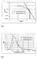
- FIG. 3 shows an exemplary diagram of two partial pressure curves during the dilution of the exhaust gas at different exhaust gas temperatures (T (exhaust)) at outlet 5 and the associated saturation curve.
- T exhaust gas temperatures
Landscapes
- Engineering & Computer Science (AREA)
- Chemical & Material Sciences (AREA)
- Combustion & Propulsion (AREA)
- Mechanical Engineering (AREA)
- General Engineering & Computer Science (AREA)
- Exhaust Gas After Treatment (AREA)
- Exhaust Silencers (AREA)
Abstract
Description
- Fig.
- 1 eine schematische Skizze einer bevorzugten Ausführung einer erfindungsgemäßen Abgasanlage in der Draufsicht
- Fig. 2
- einen Schnitt entlang der Linie II-II von Figur 1 durch einen Teil der erfindungsgemäßen Abgasanlage
- Fig. 3
- ein beispielhaftes Diagramm von Druckkurven für zwei verschiedene Abgastemperaturen während der Verdünnung des Abgases
- Fig. 4
- ein beispielhaftes Diagramm von zwei Partialdruck- und Sättigungsdruckverhältnissen aufgetragen über dem Verdünnungsverhältnis Abgas in Umgebungsluft
Claims (6)
- Abgasanlage für Kraftfahrzeuge,
dadurch gekennzeichnet, daß
die Abgase die Abgasanlage mit erhöhter Temperatur verlassen. - Abgasanlage für Kraftfahrzeuge nach Anspruch 1,
dadurch gekennzeichnet, daß
die Abgasanlage mit einer Isolierung (7) gegen Temperaturverlust versehen ist. - Abgasanlage für Kraftfahrzeuge nach Anspruch 1 oder 2,
dadurch gekennzeichnet, daß
die Abgasanlage mit einer Vorrichtung zur Abschirmung der Abgasanlage gegen den Fahrtwind versehen ist. - Abgasanlage für Kraftfahrzeuge nach Anspruch 1, 2 oder 3,
dadurch gekennzeichnet, daß
die Abgasanlage mit einer Vorrichtung zur Erhöhung der Abgastemperatur versehen ist. - Abgasanlage für Kraftfahrzeuge nach Anspruch 4,
dadurch gekennzeichnet, daß
die Vorrichtung zur Erhöhung der Temperatur eine elektrische Widerstandsheizung ist. - Abgasanlage für Kraftfahrzeuge nach Anspruch 4,
dadurch gekennzeichnet, daß
die Vorrichtung zur Erhöhung der Temperatur eine Heizung enthält, die den mitgeführten Brennstoff des Kraftfahrzeuges verwendet.
Priority Applications (2)
| Application Number | Priority Date | Filing Date | Title |
|---|---|---|---|
| DE50206315T DE50206315D1 (de) | 2002-08-17 | 2002-08-17 | Vorrichtung zum Reinigen von Abgasen von Brennkraftmaschinen |
| EP02018550A EP1391591B1 (de) | 2002-08-17 | 2002-08-17 | Vorrichtung zum Reinigen von Abgasen von Brennkraftmaschinen |
Applications Claiming Priority (1)
| Application Number | Priority Date | Filing Date | Title |
|---|---|---|---|
| EP02018550A EP1391591B1 (de) | 2002-08-17 | 2002-08-17 | Vorrichtung zum Reinigen von Abgasen von Brennkraftmaschinen |
Publications (2)
| Publication Number | Publication Date |
|---|---|
| EP1391591A1 true EP1391591A1 (de) | 2004-02-25 |
| EP1391591B1 EP1391591B1 (de) | 2006-04-05 |
Family
ID=30775811
Family Applications (1)
| Application Number | Title | Priority Date | Filing Date |
|---|---|---|---|
| EP02018550A Expired - Lifetime EP1391591B1 (de) | 2002-08-17 | 2002-08-17 | Vorrichtung zum Reinigen von Abgasen von Brennkraftmaschinen |
Country Status (2)
| Country | Link |
|---|---|
| EP (1) | EP1391591B1 (de) |
| DE (1) | DE50206315D1 (de) |
Citations (4)
| Publication number | Priority date | Publication date | Assignee | Title |
|---|---|---|---|---|
| DE3714761A1 (de) * | 1987-05-02 | 1988-11-17 | Witzenmann Metallschlauchfab | Abgasleitung fuer verbrennungsmotoren |
| US5456079A (en) * | 1991-09-12 | 1995-10-10 | Firma J. Eberspacher | Device for the thermal regeneration of particle filters for diesel engine exhaust gas |
| US5806307A (en) * | 1995-08-25 | 1998-09-15 | Honda Giken Kogyo Kabushiki Kaisha | Exhaust gas-purifying system for internal combustion engines |
| GB2347970A (en) * | 1999-03-13 | 2000-09-20 | Ford Global Tech Inc | Motor vehicle exhaust system insulated downstream of catalytic converter |
-
2002
- 2002-08-17 DE DE50206315T patent/DE50206315D1/de not_active Expired - Lifetime
- 2002-08-17 EP EP02018550A patent/EP1391591B1/de not_active Expired - Lifetime
Patent Citations (4)
| Publication number | Priority date | Publication date | Assignee | Title |
|---|---|---|---|---|
| DE3714761A1 (de) * | 1987-05-02 | 1988-11-17 | Witzenmann Metallschlauchfab | Abgasleitung fuer verbrennungsmotoren |
| US5456079A (en) * | 1991-09-12 | 1995-10-10 | Firma J. Eberspacher | Device for the thermal regeneration of particle filters for diesel engine exhaust gas |
| US5806307A (en) * | 1995-08-25 | 1998-09-15 | Honda Giken Kogyo Kabushiki Kaisha | Exhaust gas-purifying system for internal combustion engines |
| GB2347970A (en) * | 1999-03-13 | 2000-09-20 | Ford Global Tech Inc | Motor vehicle exhaust system insulated downstream of catalytic converter |
Also Published As
| Publication number | Publication date |
|---|---|
| EP1391591B1 (de) | 2006-04-05 |
| DE50206315D1 (de) | 2006-05-18 |
Similar Documents
| Publication | Publication Date | Title |
|---|---|---|
| DE112007002155B4 (de) | Abgasbehandlungs-Aufnahmevorrichtung, -System und -Verfahren | |
| DE10139424B4 (de) | Abgasanlage eines Kraftfahrzeugs | |
| EP2557288B1 (de) | Vorrichtung und Verfahren zur Abgasreinigung für Verbrennungskraftmaschinen | |
| DE4007516A1 (de) | Dieselmotor | |
| DE2233907A1 (de) | Reaktoranlage zur reinigung von aus verbrennungskraftmaschinen austretendem gas | |
| DE102010021651B4 (de) | Koordiniertes Steuerungssystem für einen Motor und ein stufenlos verstellbares Getriebe | |
| DE102012024260A1 (de) | Verfahren und Vorrichtung zur Anhebung der Abgastemperatur im Abgastrakt einer turboaufgeladenen Brennkraftmaschine | |
| DE102005040526A1 (de) | Kurbelgehäuseventilationssystem | |
| DE102017113712A1 (de) | Abgasnachbehandlungssystem und Verfahren zur Abgasnachbehandlung eines Verbrennungsmotors | |
| EP1405995A1 (de) | Motorsystem mit Abgasturbolader und Abgasrückführung sowie Verfahren zu dessen Betrieb | |
| DE60007037T3 (de) | Vorrichtung und Verfahren zur Behandlung von Partikeln und Stickoxyden für eine Brennkraftmaschine | |
| DE102017222235A1 (de) | Verfahren und Vorrichtung zur Aufheizung einer Abgasreinigungsanlage einer Brennkraftmaschine | |
| DE102017103560B4 (de) | Verbrennungsmotor und Verfahren zur Regeneration eines Partikelfilters im Abgaskanal eines Verbrennungsmotors | |
| DE3711101A1 (de) | Abgaskruemmer mit einem katalytisch beschichteten filter fuer festkoerperteilchen | |
| DE102005062398B4 (de) | Regenerieren eines Partikelfilters mit einer oxidationskatalytischen Beschichtung | |
| EP2035674A1 (de) | Verfahren zum betreiben einer in einem abgasbereich einer brennkraftmaschine angeordneten abgasreinigungsanlage | |
| DE102010026868A1 (de) | Rußfilter mit schrägen Wellschichten | |
| DE102019204298A1 (de) | Abgasreinigungsvorrichtung, damit ausgestattete Brennkraftmaschine und Verfahren zur Abgasreinigung | |
| DE102017118214A1 (de) | Abgasnachbehandlungssystem sowie Verfahren zur Abgasnachbehandlung eines Verbrennungsmotors | |
| EP1391591B1 (de) | Vorrichtung zum Reinigen von Abgasen von Brennkraftmaschinen | |
| DE10137050A1 (de) | Vorrichtung und Verfahren zur Abgasbehandlung einer Brennkraftmaschine | |
| DE102007056102B4 (de) | Verfahren zum Betreiben eines Verbrennungsmotors und eines daran angeschlossenen Abgasnachbehandlungssystems mit einem Partikelfilter und einem SCR-Katalysator | |
| DE602004003034T2 (de) | Ein Abgassystem für einen Dieselmotor | |
| EP1957767B1 (de) | Verfahren zur abgasnachbehandlung bei verbrennungsmotoren, und vorrichtung zur durchführung dieses verfahrens | |
| DE102019006494B4 (de) | Abgasanlage für eine Verbrennungskraftmaschine eines Kraftfahrzeugs, Antriebseinrichtung für ein Kraftfahrzeug sowie Kraftfahrzeug |
Legal Events
| Date | Code | Title | Description |
|---|---|---|---|
| PUAI | Public reference made under article 153(3) epc to a published international application that has entered the european phase |
Free format text: ORIGINAL CODE: 0009012 |
|
| AK | Designated contracting states |
Kind code of ref document: A1 Designated state(s): AT BE BG CH CY CZ DE DK EE ES FI FR GB GR IE IT LI LU MC NL PT SE SK TR |
|
| AX | Request for extension of the european patent |
Extension state: AL LT LV MK RO SI |
|
| 17P | Request for examination filed |
Effective date: 20040825 |
|
| 17Q | First examination report despatched |
Effective date: 20040924 |
|
| AKX | Designation fees paid |
Designated state(s): DE FR GB |
|
| RAP1 | Party data changed (applicant data changed or rights of an application transferred) |
Owner name: FORD GLOBAL TECHNOLOGIES, LLC |
|
| GRAP | Despatch of communication of intention to grant a patent |
Free format text: ORIGINAL CODE: EPIDOSNIGR1 |
|
| GRAS | Grant fee paid |
Free format text: ORIGINAL CODE: EPIDOSNIGR3 |
|
| GRAA | (expected) grant |
Free format text: ORIGINAL CODE: 0009210 |
|
| AK | Designated contracting states |
Kind code of ref document: B1 Designated state(s): DE FR GB |
|
| REG | Reference to a national code |
Ref country code: GB Ref legal event code: FG4D Free format text: NOT ENGLISH |
|
| RAP2 | Party data changed (patent owner data changed or rights of a patent transferred) |
Owner name: FORD GLOBAL TECHNOLOGIES, LLC. |
|
| REF | Corresponds to: |
Ref document number: 50206315 Country of ref document: DE Date of ref document: 20060518 Kind code of ref document: P |
|
| GBT | Gb: translation of ep patent filed (gb section 77(6)(a)/1977) |
Effective date: 20060726 |
|
| ET | Fr: translation filed | ||
| PLBE | No opposition filed within time limit |
Free format text: ORIGINAL CODE: 0009261 |
|
| STAA | Information on the status of an ep patent application or granted ep patent |
Free format text: STATUS: NO OPPOSITION FILED WITHIN TIME LIMIT |
|
| 26N | No opposition filed |
Effective date: 20070108 |
|
| PGFP | Annual fee paid to national office [announced via postgrant information from national office to epo] |
Ref country code: FR Payment date: 20090806 Year of fee payment: 8 |
|
| PGFP | Annual fee paid to national office [announced via postgrant information from national office to epo] |
Ref country code: DE Payment date: 20090831 Year of fee payment: 8 Ref country code: GB Payment date: 20090708 Year of fee payment: 8 |
|
| GBPC | Gb: european patent ceased through non-payment of renewal fee |
Effective date: 20100817 |
|
| REG | Reference to a national code |
Ref country code: FR Ref legal event code: ST Effective date: 20110502 |
|
| REG | Reference to a national code |
Ref country code: DE Ref legal event code: R119 Ref document number: 50206315 Country of ref document: DE Effective date: 20110301 |
|
| PG25 | Lapsed in a contracting state [announced via postgrant information from national office to epo] |
Ref country code: DE Free format text: LAPSE BECAUSE OF NON-PAYMENT OF DUE FEES Effective date: 20110301 Ref country code: FR Free format text: LAPSE BECAUSE OF NON-PAYMENT OF DUE FEES Effective date: 20100831 |
|
| PG25 | Lapsed in a contracting state [announced via postgrant information from national office to epo] |
Ref country code: GB Free format text: LAPSE BECAUSE OF NON-PAYMENT OF DUE FEES Effective date: 20100817 |