EP1391354A2 - Airbagmodul - Google Patents
Airbagmodul Download PDFInfo
- Publication number
- EP1391354A2 EP1391354A2 EP03017315A EP03017315A EP1391354A2 EP 1391354 A2 EP1391354 A2 EP 1391354A2 EP 03017315 A EP03017315 A EP 03017315A EP 03017315 A EP03017315 A EP 03017315A EP 1391354 A2 EP1391354 A2 EP 1391354A2
- Authority
- EP
- European Patent Office
- Prior art keywords
- airbag
- propellant
- generator housing
- airbag module
- vehicle
- Prior art date
- Legal status (The legal status is an assumption and is not a legal conclusion. Google has not performed a legal analysis and makes no representation as to the accuracy of the status listed.)
- Granted
Links
- 239000003380 propellant Substances 0.000 claims abstract description 25
- 239000002360 explosive Substances 0.000 claims abstract description 4
- 238000000034 method Methods 0.000 claims abstract description 3
- 239000004604 Blowing Agent Substances 0.000 description 1
- 238000004873 anchoring Methods 0.000 description 1
- 238000003780 insertion Methods 0.000 description 1
- 230000037431 insertion Effects 0.000 description 1
- 230000007257 malfunction Effects 0.000 description 1
- 230000008439 repair process Effects 0.000 description 1
Images
Classifications
-
- B—PERFORMING OPERATIONS; TRANSPORTING
- B60—VEHICLES IN GENERAL
- B60R—VEHICLES, VEHICLE FITTINGS, OR VEHICLE PARTS, NOT OTHERWISE PROVIDED FOR
- B60R21/00—Arrangements or fittings on vehicles for protecting or preventing injuries to occupants or pedestrians in case of accidents or other traffic risks
- B60R21/02—Occupant safety arrangements or fittings, e.g. crash pads
- B60R21/16—Inflatable occupant restraints or confinements designed to inflate upon impact or impending impact, e.g. air bags
- B60R21/26—Inflatable occupant restraints or confinements designed to inflate upon impact or impending impact, e.g. air bags characterised by the inflation fluid source or means to control inflation fluid flow
-
- B—PERFORMING OPERATIONS; TRANSPORTING
- B60—VEHICLES IN GENERAL
- B60R—VEHICLES, VEHICLE FITTINGS, OR VEHICLE PARTS, NOT OTHERWISE PROVIDED FOR
- B60R21/00—Arrangements or fittings on vehicles for protecting or preventing injuries to occupants or pedestrians in case of accidents or other traffic risks
- B60R21/02—Occupant safety arrangements or fittings, e.g. crash pads
- B60R21/16—Inflatable occupant restraints or confinements designed to inflate upon impact or impending impact, e.g. air bags
- B60R21/26—Inflatable occupant restraints or confinements designed to inflate upon impact or impending impact, e.g. air bags characterised by the inflation fluid source or means to control inflation fluid flow
- B60R21/264—Inflatable occupant restraints or confinements designed to inflate upon impact or impending impact, e.g. air bags characterised by the inflation fluid source or means to control inflation fluid flow using instantaneous generation of gas, e.g. pyrotechnic
- B60R21/2644—Inflatable occupant restraints or confinements designed to inflate upon impact or impending impact, e.g. air bags characterised by the inflation fluid source or means to control inflation fluid flow using instantaneous generation of gas, e.g. pyrotechnic using only solid reacting substances, e.g. pellets, powder
Definitions
- the invention relates to an airbag module, as in the preamble of Claim 1 is described. Furthermore, the subject of the invention a method according to claim 5 for installing an airbag module in a vehicle, especially a motor vehicle.
- Airbag modules of the known type consist at least of the sub-elements Airbag and gas generator with its the gas volume for that Inflating the propellant that produces the airbag. More mechanical Parts, such as housing sections, brackets, etc. usually complete that Airbag module. All parts of the overall module thus constructed are on the ground legal requirements firmly connected and the overall module may only be transported in this training. It should be ensured that the propellant burns without recoil in the event of an unwanted ignition.
- the installed in the vehicle Airbag module the entire system removed and by igniting the propellant made unusable. It actually monitors the on-board System but only the electrical contacts through which the ignition of the Propellant is initiated. That is, an error is reported here the airbag and the other mechanical parts could still be in order and should not be removed and destroyed.
- the object of the invention is to design a generic airbag module so that it is easily transported, stored and installed in the vehicle and can also be repaired inexpensively.
- the invention allows the propellant to be introduced into the generator housing, after the airbag module is already installed in the vehicle. On in this way the "not yet loaded” airbag module can be used in any Quantities are transported and stored.
- this can also be introduced once Propellant can be removed from the generator housing. On This saves considerable costs in the event of repairs, as otherwise intact airbag module only the propellant with the squib and the electrical connections need to be replaced.
- the blowing agent is arranged on an end plate by a suitable, detachable Closure can be connected to the generator housing.
- a suitable, detachable Closure can be connected to the generator housing.
- a hollow cylinder forms the generator housing into which the base plate screwed into an end face provided as an insertion opening for the propellant and closes the housing.
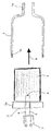
- the drawing shows in a single figure and in a schematic manner the parts of an airbag module that are necessary for an understanding of the invention.
- the airbag module can be installed anywhere in a motor vehicle, for example in the roof area.
- a generator housing 1 in the form of a hollow cylinder is indicated, one end of which narrows to a gas duct 1a.
- This An airbag is assigned to the gas guide channel either attached directly to it or via other pipe sections is taken care of by him. It is only important that the gas generator 1, the airbag and the possibly further pipe sections and anchoring elements form a firmly connected, non-detachable unit and in it Entire be transported, stored and assembled.
- the the gas duct 1a opposite end of the hollow cylindrical generator housing 1 is open, but points to the inner wall of the Cylinder jacket on an internal thread 1b.
- An end plate 2 with a fitting to the internal thread 1b External thread 2a carries an explosive propellant 3.
- This propellant 3 can be represented in any known form; it just needs the condition of "recoil-free burning".
- Near the end plate 2 there is a squib 4 in the propellant 3, to which electrical lines 5 and 6 pass through the end plate 2.
- the generator housing When installing the airbag module in the motor vehicle, the generator housing is first and the parts connected to it, in particular the Airbag, the housing that usually surrounds it with fastening sections etc. mounted. Then the propellant 3 is in the housing inserted - indicated by an arrow 8. The with the propellant 3 connected base plate 2 is screwed to the generator housing and the plug 7 is connected to the vehicle electrical system. This is the airbag module operational. In the event of a crash, electrical lines 5 and 6 activates the squib 4 and ignites the propellant 3. That from him generated gas volume becomes an airbag via the gas duct 1a headed, which unfolds as intended.
Landscapes
- Physics & Mathematics (AREA)
- Fluid Mechanics (AREA)
- Engineering & Computer Science (AREA)
- Mechanical Engineering (AREA)
- Air Bags (AREA)
Abstract
Description
Claims (5)
- Airbagmodul, das wenigstens aus den miteinander verbundenen Elementen Luftsack und Generatorgehäuse besteht und als solche Einheit in ein Fahrzeug einbaubar ist, und bei dem ein im Generatorgehäuse vorgesehenes explosives Treibmittel beim Zünden des Airbags ein Gasvolumen für das Aufblasen des Luftsacks erzeugt, dadurch gekennzeichnet, dass das Treibmittel (3) bei eingebautem Airbagmodul in das Generatorgehäuse (1) einbringbar ist.
- Airbagmodul nach Anspruch 1, dadurch gekennzeichnet, dass sich das Treibmittel (3) aus dem im Fahrzeug eingebauten Generatorgehäuse (1) entfernen lässt.
- Airbagmodul nach Anspruch 2, dadurch gekennzeichnet, dass ein Hohlzylinder das Generatorgehäuse (1) bildet, dessen eine Stirnseite mit dem Luftsack in Verbindung steht und dessen gegenüberliegende Stirnseite das Einbringen des Treibmittels (3) erlaubt.
- Airbagmodul nach Anspruch 3, dadurch gekennzeichnet, dass die Stirnseite des Generatorgehäuses (1) zum Einbringen des Treibmittels (3) ein Innengewinde (1b) aufweist und dass das Treibmittel (3) auf einer Abschlussplatte (2) mit einem in das Innengewinde (1b) einschraubbaren Außengewinde (2a) angeordnet ist.
- Verfahren zum Montieren eines Airbagmoduls in ein Fahrzeug, insbesondere Kraftfahrzeug, wobei das Airbagmodul wenigstens aus den miteinander verbundenen Elementen Luftsack und Generatorgehäuse besteht und ein im Generatorgehäuse vorgesehenes explosives Treibmittel beim Zünden des Airbags ein Gasvolumen für das Aufblasen des Luftsacks erzeugt, dadurch gekennzeichnet, dass die unlösbare Einheit aus Luftsack und Generatorgehäuse (1) in das Fahrzeug eingebaut und sodann das Generatorgehäuse (1) mit dem Treibmittel (3) befüllt wird.
Applications Claiming Priority (2)
| Application Number | Priority Date | Filing Date | Title |
|---|---|---|---|
| DE2002137727 DE10237727A1 (de) | 2002-08-17 | 2002-08-17 | Airbagmodul |
| DE10237727 | 2002-08-17 |
Publications (3)
| Publication Number | Publication Date |
|---|---|
| EP1391354A2 true EP1391354A2 (de) | 2004-02-25 |
| EP1391354A3 EP1391354A3 (de) | 2004-06-16 |
| EP1391354B1 EP1391354B1 (de) | 2006-06-14 |
Family
ID=30775380
Family Applications (1)
| Application Number | Title | Priority Date | Filing Date |
|---|---|---|---|
| EP20030017315 Expired - Lifetime EP1391354B1 (de) | 2002-08-17 | 2003-07-31 | Airbagmodul |
Country Status (2)
| Country | Link |
|---|---|
| EP (1) | EP1391354B1 (de) |
| DE (2) | DE10237727A1 (de) |
Family Cites Families (4)
| Publication number | Priority date | Publication date | Assignee | Title |
|---|---|---|---|---|
| JPH1067289A (ja) * | 1996-08-29 | 1998-03-10 | Aisin Seiki Co Ltd | 車両用エアバッグ装置 |
| DE29907617U1 (de) * | 1999-04-29 | 1999-09-16 | TRW Occupant Restraint Systems GmbH & Co. KG, 73553 Alfdorf | Gasgenerator und Vorrichtung zum Aufblasen eines Fahrzeuginsassen-Rückhaltesystems |
| DE19947262A1 (de) * | 1999-09-30 | 2001-04-05 | Opel Adam Ag | Beifahrer-Airbagmodul für Kraftfahrzeuge |
| DE20020101U1 (de) * | 2000-11-27 | 2001-04-05 | TRW Airbag Systems GmbH & Co. KG, 84544 Aschau | Gaserzeugungsvorrichtung |
-
2002
- 2002-08-17 DE DE2002137727 patent/DE10237727A1/de not_active Withdrawn
-
2003
- 2003-07-31 EP EP20030017315 patent/EP1391354B1/de not_active Expired - Lifetime
- 2003-07-31 DE DE50303790T patent/DE50303790D1/de not_active Expired - Fee Related
Non-Patent Citations (1)
| Title |
|---|
| None |
Also Published As
| Publication number | Publication date |
|---|---|
| DE10237727A1 (de) | 2004-03-11 |
| DE50303790D1 (de) | 2006-07-27 |
| EP1391354A3 (de) | 2004-06-16 |
| EP1391354B1 (de) | 2006-06-14 |
Similar Documents
| Publication | Publication Date | Title |
|---|---|---|
| EP2627541B1 (de) | Gasgenerator und gassackmodul | |
| DE69718101T2 (de) | Gerichtete Druckgas-Aufblasvorrichtung | |
| EP0501040A1 (de) | Boden eines Fahrzeuginnenraums mit wenigstens einem Bereich aus bruchgefährdetem Material | |
| DE2265376B1 (de) | Aufblasbare Aufprallschutzvorrichtung fuer Fahrzeuginsassen | |
| DE102007029097A1 (de) | Überrollschutzsystem für Kraftfahrzeuge mit zumindest einem aktiv aufstellbaren Überrollkörper | |
| EP0653336A1 (de) | Gasgenerator | |
| EP3571097B1 (de) | Hybridgasgenerator, verfahren zum betreiben eines hybridgasgenerators, gassackmodul und fahrzeugsicherheitssystem | |
| DE102021208376A1 (de) | Fahrzeug mit einem Batteriesystem und mit einer Vorrichtung zum Entgasen und/oder Kühlen und/oder Löschen des Batteriesystems des Fahrzeuges | |
| DE202005011878U1 (de) | Airbagmodul für ein Kraftfahrzeug | |
| EP1721789A1 (de) | Gasgenerator | |
| EP1010592B1 (de) | Vorrichtung zum Aufblasen eines Fahrzeuginsassen-Rückhaltesystems | |
| EP1137895A1 (de) | Vorrichtung und verfahren zum umwandeln des boil-off-gases von kryo-kraftstofftanks | |
| DE69600257T2 (de) | Verzahnter Adapter für einen Gasgenerator einer Gassack-Aufprall-Schutzeinrichtung | |
| DE102010040119A1 (de) | Gassack für ein Personen-Schutzsystem eines Fahrzeugs und Verfahren zu dessen Herstellung | |
| DE2141405C3 (de) | Druckgaszufuhreinheit einer Gassack-Aufprallschutzvorrichtung | |
| EP1391354A2 (de) | Airbagmodul | |
| DE19623578B4 (de) | Airbagmodul | |
| WO2009043791A1 (de) | Aufblaseinrichtung für ein airbagmodul | |
| DE102007046822A1 (de) | Brennkammerbaueinheit für ein Airbagmodul | |
| EP1715195B1 (de) | Pyrotechnische Einheit für ein Sicherheitssystem, insbesondere eines Airbags oder eines Gurtstraffers eines Fahrzeugs | |
| EP1207086B1 (de) | Airbagbaueinheit | |
| DE29613269U1 (de) | Gassack-Modul für ein Fahrzeuginsassen-Rückhaltesystem | |
| EP1088711A2 (de) | Beifahrer-Airbagmodul für Kraftfahrzeuge | |
| DE202005000818U1 (de) | Gassack für eine Fahrzeuginsassen-Rückhaltevorrichtung | |
| DE102016107114B3 (de) | Gasgeneratorbaugruppe |
Legal Events
| Date | Code | Title | Description |
|---|---|---|---|
| PUAI | Public reference made under article 153(3) epc to a published international application that has entered the european phase |
Free format text: ORIGINAL CODE: 0009012 |
|
| AK | Designated contracting states |
Kind code of ref document: A2 Designated state(s): AT BE BG CH CY CZ DE DK EE ES FI FR GB GR HU IE IT LI LU MC NL PT RO SE SI SK TR |
|
| AX | Request for extension of the european patent |
Extension state: AL LT LV MK |
|
| PUAL | Search report despatched |
Free format text: ORIGINAL CODE: 0009013 |
|
| AK | Designated contracting states |
Kind code of ref document: A3 Designated state(s): AT BE BG CH CY CZ DE DK EE ES FI FR GB GR HU IE IT LI LU MC NL PT RO SE SI SK TR |
|
| AX | Request for extension of the european patent |
Extension state: AL LT LV MK |
|
| 17P | Request for examination filed |
Effective date: 20040525 |
|
| 17Q | First examination report despatched |
Effective date: 20050124 |
|
| AKX | Designation fees paid |
Designated state(s): DE FR GB IT |
|
| GRAP | Despatch of communication of intention to grant a patent |
Free format text: ORIGINAL CODE: EPIDOSNIGR1 |
|
| GRAS | Grant fee paid |
Free format text: ORIGINAL CODE: EPIDOSNIGR3 |
|
| GRAA | (expected) grant |
Free format text: ORIGINAL CODE: 0009210 |
|
| AK | Designated contracting states |
Kind code of ref document: B1 Designated state(s): DE FR GB IT |
|
| REG | Reference to a national code |
Ref country code: GB Ref legal event code: FG4D Free format text: NOT ENGLISH |
|
| GBT | Gb: translation of ep patent filed (gb section 77(6)(a)/1977) |
Effective date: 20060626 |
|
| REF | Corresponds to: |
Ref document number: 50303790 Country of ref document: DE Date of ref document: 20060727 Kind code of ref document: P |
|
| PGFP | Annual fee paid to national office [announced via postgrant information from national office to epo] |
Ref country code: IT Payment date: 20060731 Year of fee payment: 4 |
|
| PGFP | Annual fee paid to national office [announced via postgrant information from national office to epo] |
Ref country code: DE Payment date: 20060830 Year of fee payment: 4 |
|
| ET | Fr: translation filed | ||
| PLBE | No opposition filed within time limit |
Free format text: ORIGINAL CODE: 0009261 |
|
| STAA | Information on the status of an ep patent application or granted ep patent |
Free format text: STATUS: NO OPPOSITION FILED WITHIN TIME LIMIT |
|
| 26N | No opposition filed |
Effective date: 20070315 |
|
| GBPC | Gb: european patent ceased through non-payment of renewal fee |
Effective date: 20070731 |
|
| PG25 | Lapsed in a contracting state [announced via postgrant information from national office to epo] |
Ref country code: DE Free format text: LAPSE BECAUSE OF NON-PAYMENT OF DUE FEES Effective date: 20080201 |
|
| PG25 | Lapsed in a contracting state [announced via postgrant information from national office to epo] |
Ref country code: GB Free format text: LAPSE BECAUSE OF NON-PAYMENT OF DUE FEES Effective date: 20070731 |
|
| REG | Reference to a national code |
Ref country code: FR Ref legal event code: ST Effective date: 20080331 |
|
| PG25 | Lapsed in a contracting state [announced via postgrant information from national office to epo] |
Ref country code: FR Free format text: LAPSE BECAUSE OF NON-PAYMENT OF DUE FEES Effective date: 20070731 |
|
| PG25 | Lapsed in a contracting state [announced via postgrant information from national office to epo] |
Ref country code: FR Free format text: LAPSE BECAUSE OF NON-PAYMENT OF DUE FEES Effective date: 20060731 |
|
| PG25 | Lapsed in a contracting state [announced via postgrant information from national office to epo] |
Ref country code: IT Free format text: LAPSE BECAUSE OF NON-PAYMENT OF DUE FEES Effective date: 20070731 |