EP1391172A1 - Appareil électroménager de préparation culinaire comportant un outil rotatif et un double dispositif de sécurité amélioré - Google Patents
Appareil électroménager de préparation culinaire comportant un outil rotatif et un double dispositif de sécurité amélioré Download PDFInfo
- Publication number
- EP1391172A1 EP1391172A1 EP03356120A EP03356120A EP1391172A1 EP 1391172 A1 EP1391172 A1 EP 1391172A1 EP 03356120 A EP03356120 A EP 03356120A EP 03356120 A EP03356120 A EP 03356120A EP 1391172 A1 EP1391172 A1 EP 1391172A1
- Authority
- EP
- European Patent Office
- Prior art keywords
- housing
- rod
- working container
- household
- switch
- Prior art date
- Legal status (The legal status is an assumption and is not a legal conclusion. Google has not performed a legal analysis and makes no representation as to the accuracy of the status listed.)
- Granted
Links
- 235000013305 food Nutrition 0.000 claims abstract description 7
- 230000005540 biological transmission Effects 0.000 claims description 29
- 238000001514 detection method Methods 0.000 claims description 24
- 230000000903 blocking effect Effects 0.000 claims description 11
- 238000002360 preparation method Methods 0.000 claims description 8
- 239000011521 glass Substances 0.000 claims description 4
- 239000000463 material Substances 0.000 claims description 3
- 235000021478 household food Nutrition 0.000 claims 3
- 239000002241 glass-ceramic Substances 0.000 claims 1
- 238000010276 construction Methods 0.000 description 9
- 238000004140 cleaning Methods 0.000 description 5
- 238000007789 sealing Methods 0.000 description 3
- 238000005520 cutting process Methods 0.000 description 2
- 239000006185 dispersion Substances 0.000 description 2
- 210000000056 organ Anatomy 0.000 description 2
- 239000000919 ceramic Substances 0.000 description 1
- 230000000295 complement effect Effects 0.000 description 1
- 238000009432 framing Methods 0.000 description 1
- 230000014759 maintenance of location Effects 0.000 description 1
- 238000004519 manufacturing process Methods 0.000 description 1
- 239000002184 metal Substances 0.000 description 1
- 238000012986 modification Methods 0.000 description 1
- 230000004048 modification Effects 0.000 description 1
- 238000003825 pressing Methods 0.000 description 1
Images

Classifications
-
- A—HUMAN NECESSITIES
- A47—FURNITURE; DOMESTIC ARTICLES OR APPLIANCES; COFFEE MILLS; SPICE MILLS; SUCTION CLEANERS IN GENERAL
- A47J—KITCHEN EQUIPMENT; COFFEE MILLS; SPICE MILLS; APPARATUS FOR MAKING BEVERAGES
- A47J43/00—Implements for preparing or holding food, not provided for in other groups of this subclass
- A47J43/04—Machines for domestic use not covered elsewhere, e.g. for grinding, mixing, stirring, kneading, emulsifying, whipping or beating foodstuffs, e.g. power-driven
- A47J43/07—Parts or details, e.g. mixing tools, whipping tools
- A47J43/075—Safety devices
- A47J43/0755—Safety devices for machines with tools driven from the upper side
-
- A—HUMAN NECESSITIES
- A47—FURNITURE; DOMESTIC ARTICLES OR APPLIANCES; COFFEE MILLS; SPICE MILLS; SUCTION CLEANERS IN GENERAL
- A47J—KITCHEN EQUIPMENT; COFFEE MILLS; SPICE MILLS; APPARATUS FOR MAKING BEVERAGES
- A47J43/00—Implements for preparing or holding food, not provided for in other groups of this subclass
- A47J43/04—Machines for domestic use not covered elsewhere, e.g. for grinding, mixing, stirring, kneading, emulsifying, whipping or beating foodstuffs, e.g. power-driven
- A47J43/07—Parts or details, e.g. mixing tools, whipping tools
- A47J43/0705—Parts or details, e.g. mixing tools, whipping tools for machines with tools driven from the upper side
Definitions
- the present invention relates to the general technical field of apparatus kitchen appliances with a rotary tool.
- the present invention relates more particularly, but not exclusively, mini choppers with a cutting working tool rotating in a working container, in which the tool is driven by a motor arranged in a box placed above the working container.
- mini mincers can include an on / off switch arranged in the housing and controlled by the contact of a transmission rod with the upper part of the working container. To start the device the user presses on the case or turns the case placed on the container.
- a switch can be ordered by a control button arranged on the housing.
- a sealing piece between the container and the motor housing, presenting usually in the form of a cup.
- the shutter closes the upper part of the container and has an opening having a diameter slightly greater than the tool rod driven by the motor. So food splashes reach the underside of the sealing piece, likely to go into the dishwasher because it has no electrical parts, and not the underside of the motor housing.
- a switch actuated by said closure piece is provided in the housing.
- the user can assemble the motor housing and the shutter piece to set the appliance.
- Either of these embodiments makes it possible to obtain a device the operation is particularly safe, since the safety device detects both the presence of the working container and the presence the shutter piece.
- the sealing piece, or cup must be subject to special precautions for cleaning, due to the presence of moving and / or deformable parts.
- the working container has means for hooking and / or locking the closure part.
- the object of the present invention is to provide an apparatus of the aforementioned type whose operation is particularly safe, and whose construction is simplified.
- Another object of the present invention is to provide an apparatus of the type aforesaid whose cleaning of the closure part of the working container is ease.
- Another object of the present invention is to provide an apparatus of the type aforementioned whose housing has a limited size and whose operation is particularly safe.
- Another object of the present invention is to provide an apparatus of the type aforesaid whose operation is particularly safe, and whose container work does not require any particular dimensional accuracy.
- a household appliance of preparation culinary including a working container, a removable closure piece working container, a housing, arranged above the working container, accommodating a motor designed to rotate a tool placed in the container work, the engine being associated with control means housed in the housing, the control means comprising a switch, a first detection member designed to cooperate with the closure piece, as well as a second detection member designed to cooperate with the working container, the fact that the first detection member belongs to a means of transmission likely to cooperate with the switch to authorize the operation of the device, and that the second detection member belongs to a locking means comprising a blocking member cooperating with the transmission means when the second member of detection is not requested.
- the blocking member when the second organ of detection does not cooperate with the working container, the blocking member cooperates with the transmission means to block it and the means of transmission cannot cooperate with the switch to allow the operation of the device.
- the blocking member releases the means of transmission and the transmission means can cooperate with the switch for authorize the device to operate when the first detection device cooperates with the closure piece.
- the transmission means can occupy a position passive in which the switch does not authorize the operation of the device, and an unstable active position in which the switch allows the operation of the apparatus, and the locking means can occupy a stable position known as locking and an unstable position known as unlocked, the blocking member being liable to hinder the movement of the means of transmission to its active position when the locking means occupies its locking position.
- Such a construction can be carried out with simple mechanical means.
- the locking means is formed by a lock mounted mobile in the housing against a return spring. This construction is particularly simple and economical.
- the lock is mounted movable in a radial direction and the second detection member is formed by a cam surface.
- cam surface is formed on the radial end external of the lock and is laterally protected by the housing. This provision allows to limit the size of the housing while ensuring good security.
- the lock comprises a head engaged in a window of the housing, the head carrying the locking member. This provision allows maintain the blocking member when the locking means are locked transmission.
- the safety device thus obtained is reliable with a simple construction.
- the transmission means comprises a rod mounted movable in the housing against a return spring.
- This construction is also particularly simple and economical.
- the blocking member is formed by a relief of the lock cooperating with a post from the rod.
- the rod is movable mounted in an axial direction, the first detection member being formed by the lower end of the rod.
- the rod is guided by slides from the motor. This provision simplifies the safety mechanism.
- the switch can also be mounted on the engine.
- the working container has an upper part cooperating with the closure piece and the housing made of a material with geometric tolerances greater than 0.5 mm.
- the working container can in particular be made of glass or ceramic.
- Figure 1 shows an electric mini-chopper with a box of upper control 1 in which is placed a motor 2, a part shutter 3 provided to close the upper part of a working container 4 in which rotates a rotary cutting tool 5 mounted on a hub 6.
- the housing 1 has a base 28 surmounted by a cover 29, better visible in the figures 3 to 5.
- Control means 8 mounted in the housing 1 comprise a first detection member 9, designed to cooperate with the closure part 3, and a second detection member 10, provided to cooperate with the working container 4.
- the control means 8 include a control rod 11 slidably mounted relative to the motor 2 in slides 12, 22.
- the rod 11 cooperates with a switch 13 secured to the case 1, namely an arm 14 of a spring 15 mounted on a tenon of the case and likely to come into contact with a metal terminal 16.
- the rod 11 has a notch 17, the upper part of which forms a cam 18.
- the control rod 11 is held in the lowered position shown in the Figure 2 by a return means formed by a spring 19 mounted around a tongue 20 secured to the rod 11 and bearing under the slide 12.
- the slides 12, 22 come from the carcass of the motor 2.
- the rod 11 is movable in an axial direction corresponding in the housing 1 to the axis of transmission provided to drive the tool 5.
- the lower end of the control rod 11 forms the first member of detection 9 intended to cooperate with the closure part 3. As visible in Figures 3 to 5, the lower end of the control rod 11 leaves the housing 1 through an opening in the underside of the base 28. The lower end of the control rod 11 is provided to cooperate with a lug 34 formed on the upper face of the closure piece 3.
- a lock 40 is mounted movable in translation in a radial direction on the base 28 of the housing 1.
- the lock 40 comprises a body 41 partially arranged in a housing 50 formed in the base 28.
- the body 41 is guided by relative to the base 28 by two pairs of ribs 42, 43 framing two ribs 51 partially closing the housing 50, better visible in FIG. 2.
- the body 41 has an external radial end comprising a surface of cam 44.
- the cam surface 44 forms the second detection member 10 provided for cooperate with the working container 4.
- the cam surface 44 is protected laterally by the housing 1, the external radial end of the body 41 being housed behind a cover 60 from the cover 29 of the housing 1.
- the base 28 of the housing 1 cleaning with the cover 29 an opening 31 provided to allow actuation of the cam surface 44 by the upper edge of the container work 4.
- the body 41 is extended by a head 45 mounted sliding in a window 52 of the base 28.
- the head 45 has a cavity lower 46 provided to receive a tenon 57 coming from the rod 11.
- the cavity 46 is extended radially inward by a relief 47.
- the tenon 57 goes around the window 52.
- a spring 48 is arranged between the base 28 and the latch 40 to push the latch 40 radially outwards against the cover 60.
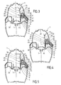
- Figure 3 shows the device in the waiting position, the shutter 3 being in place in the working container 4, and the housing 1 being placed on the working container 4.
- the upper edge of working container 4 comes into contact with the cam surface 44 belonging to the latch 40 pushed back by the spring 48.
- the lower end of the rod 11 is not yet in contact with the lug 34 of the closure part 3.
- the housing 1 is in a configuration of safety, in which the pin 57 of the rod 11 abuts against the relief 47 of the latch 40 pushed back by the spring 20.
- the head 45 of the latch 40 is held vertically in the window 52 to ensure good retention of the latch 40.
- the rod 11 cannot be pushed back to actuate the switch 13.
- the device cannot operate.
- Figure 4 shows the device in an intermediate position of the housing, called unlock position. This position is reached when the user exercises a certain axial pressure on the housing 1.
- the upper edge of the container work 4 pushes the cam surface 44.
- the latch 40 is pushed against the spring 48 and the relief 47 releases the post 57 from the rod 11.
- the lock 40 pushed back cleaning a passage for the upper edge of the working container 4 against the inner face of the cover 60.
- the lug 34 of the closure piece 3 arrives at contact with the lower end of the rod 11.
- Figure 5 shows the device in the on position. This position is reached when the user exerts an even greater axial pressure on the case 1.
- the upper edge of the working container 4 is then inserted between the latch 40 and cover 60.
- the lug 57 engaged in the cavity 46 allows the rod 11 pushed back by lug 34 to activate switch 13.
- the device can then function.
- the apparatus according to the invention By detecting the presence of the working container 4 and the part shutter 3, the apparatus according to the invention is of particular use safe. Thanks to the absence of mobile and / or deformable control parts in the container 4 and in the closure part 3, the apparatus according to the invention is particularly pleasant to use, because the parts in contact with food can be washed without particular difficulties. In addition the device retains a compact construction.
- the rod 11 forms a transmission means 70 capable of cooperating with the switch 13.
- the transmission means 70 can occupy a position passive in which the switch 13 does not authorize the operation of the device, shown in Figures 3 and 4, and an active position in which the switch 13 authorizes the operation of the device, shown in FIG. 5.
- the lock 40 forms a locking means 71 which can occupy a position stable, called locking, shown in Figure 3, and an unstable position called unlocked, shown in FIGS. 4 and 5.
- the relief 47 of the lock 40 forms a blocking member 72 liable to hinder the movement of the rod 11 in cooperating with the pin 57 of the rod 11.
- the transmission means 70 does can reach its active position when the locking means 71 occupies its locking position, as shown in Figure 3.
- the locking position of the locking means 71 is stable due to the action of the spring 48 on the latch 40.
- the unlocked position of the means of locking 71 is obtained by the cooperation of the working container 4 with the second detection device 10.
- the active position of the transmission means 70 is unstable due to the action of the spring 19 on the rod 10. This position active is permitted when the blocking member 72 of the locking means 71 released the transmission means 70. This active position is obtained when the first detection member 9 cooperates with the transmission means 70.
- the device could be operated by pressing a control button arranged on the housing, instead of direct pressure on the housing. It is also possible to consider a micro-switch, or microswitch, whose part mobile is actuated by the rod, respectively by the housing, the casing external of the micro-switch being mounted in the housing, respectively on the rod mounted in the housing.
- the transmission means and / or the locking means may contain several parts.
- a transmission part complementary can be envisaged between the rod 11 and the switch 13.
Landscapes
- Engineering & Computer Science (AREA)
- Mechanical Engineering (AREA)
- Food Science & Technology (AREA)
- Food-Manufacturing Devices (AREA)
- Baking, Grill, Roasting (AREA)
- Cookers (AREA)
Abstract
Description
- la figure 1 est une vue schématique en éclaté d'un mini-hachoir électrique selon l'invention, dans laquelle une partie de l'enveloppe du boítier a été retirée,
- la figure 2 est une vue partielle du boítier moteur du mini-hachoir montré à la figure 1, dans laquelle le couvercle du boítier a été retiré, le moteur étant figuré de manière schématique,
- la figure 3 est une vue schématique en position d'attente du mini-hachoir représenté à la figure 1, dans laquelle le moteur et l'outil rotatif ne sont pas représentés,
- la figure 4 est une vue schématique en position déverrouillée du mini-hachoir illustré à la figure 3,
- la figure 5 est une vue schématique en position marche du mini-hachoir illustré aux figures 3 et 4.
Claims (12)
- Appareil électroménager de préparation culinaire comprenant un récipient de travail (4), une pièce d'obturation (3) amovible du récipient de travail, un boítier (1), disposé au dessus du récipient de travail, logeant un moteur (2) prévu pour entraíner en rotation un outil (5) disposé dans le récipient de travail, le moteur étant associé à des moyens de commande (8) logés dans le boítier, les moyens de commande comportant un interrupteur (13), un premier organe de détection (9) prévu pour coopérer avec la pièce d'obturation, ainsi qu'un deuxième organe de détection (10) prévu pour coopérer avec le récipient de travail, caractérisé en ce que le premier organe de détection (9) appartient à un moyen de transmission (70) susceptible de coopérer avec l'interrupteur (13) pour autoriser le fonctionnement de l'appareil, et que le deuxième organe de détection (10) appartient à un moyen de verrouillage (71) comportant un organe de blocage (72) coopérant avec le moyen de transmission (70) lorsque le deuxième organe de détection (10) n'est pas sollicité.
- Appareil électroménager de préparation culinaire selon la revendication 1, caractérisé en ce que le moyen de transmission (70) peut occuper une position passive dans laquelle l'interrupteur (13) n'autorise pas le fonctionnement de l'appareil, et une position active instable dans laquelle l'interrupteur (13) autorise le fonctionnement de l'appareil, et en ce que le moyen de verrouillage (71) peut occuper une position stable dite de verrouillage et une position instable dite déverrouillée, l'organe de blocage (72) étant susceptible d'entraver le déplacement du moyen de transmission (70) vers sa position active lorsque le moyen de verrouillage (71) occupe sa position de verrouillage.
- Appareil électroménager de préparation culinaire selon l'une des revendications 1 ou 2, caractérisé en ce que le moyen de verrouillage (71) est formé par un verrou (40) monté mobile dans le boítier (1) contre un ressort de rappel (48).
- Appareil électroménager de préparation culinaire selon la revendication 3, caractérisé en ce que le verrou (40) est monté mobile selon une direction radiale et en ce que le second organe de détection (10) est formé par une surface de came (44).
- Appareil électroménager de préparation culinaire selon la revendication 4, caractérisé en ce que la surface de came (44) est ménagée sur l'extrémité radiale externe du verrou (40) et est protégée latéralement par le boítier (1).
- Appareil électroménager de préparation culinaire selon l'une des revendications 3 à 5, caractérisé en ce que le verrou (40) comporte une tête (45) engagée dans une fenêtre (52) du boítier (1), la tête (45) portant l'organe de blocage (72).
- Appareil électroménager de préparation culinaire selon l'une des revendications 1 à 6, caractérisé en ce que le moyen de transmission (70) comporte une tige (11) montée mobile dans le boítier (1) contre un ressort de rappel (19).
- Appareil électroménager de préparation culinaire selon l'une des revendications 3 à 6, caractérisé en ce que l'organe de blocage (72) est formé par un relief (47) du verrou (40) coopérant avec un tenon (57) issu d'une tige (11) montée mobile dans le boítier (1) contre un ressort de rappel (19), la tige (11) appartenant au moyen de transmission (70).
- Appareil électroménager de préparation culinaire selon l'une des revendications 7 ou 8, caractérisé en ce que la tige (11) est montée mobile selon une direction axiale et en ce que le premier organe de détection (9) est formé par l'extrémité inférieure de la tige (11).
- Appareil électroménager de préparation culinaire selon l'une des revendications 7 à 9, caractérisé en ce que la tige (11 ) est guidée par des glissières (12, 22) issues du moteur (2).
- Appareil électroménager de préparation culinaire selon l'une des revendications 1 à 10, caractérisé en ce que le récipient de travail (4) comporte une partie supérieure, coopérant avec la pièce d'obturation (3) et le boítier (1), réalisée dans une matière présentant des tolérances géométriques supérieures à 0,5 mm.
- Appareil selon l'une des revendications 1 à 11, caractérisé en ce que le récipient de travail (4) est réalisé en verre ou en vitrocéramique.
Applications Claiming Priority (2)
| Application Number | Priority Date | Filing Date | Title |
|---|---|---|---|
| FR0210388A FR2843535B1 (fr) | 2002-08-19 | 2002-08-19 | Appareil electromenager de preparation culinaire comportant un outil rotatif et un double dispositif de securite ameliore |
| FR0210388 | 2002-08-19 |
Publications (2)
| Publication Number | Publication Date |
|---|---|
| EP1391172A1 true EP1391172A1 (fr) | 2004-02-25 |
| EP1391172B1 EP1391172B1 (fr) | 2007-05-09 |
Family
ID=30776043
Family Applications (1)
| Application Number | Title | Priority Date | Filing Date |
|---|---|---|---|
| EP03356120A Expired - Lifetime EP1391172B1 (fr) | 2002-08-19 | 2003-08-06 | Appareil électroménager de préparation culinaire comportant un outil rotatif et un double dispositif de sécurité amélioré |
Country Status (5)
| Country | Link |
|---|---|
| EP (1) | EP1391172B1 (fr) |
| AT (1) | ATE361693T1 (fr) |
| DE (1) | DE60313708T2 (fr) |
| ES (1) | ES2285070T3 (fr) |
| FR (1) | FR2843535B1 (fr) |
Cited By (3)
| Publication number | Priority date | Publication date | Assignee | Title |
|---|---|---|---|---|
| CN100579434C (zh) * | 2004-06-29 | 2010-01-13 | Seb公司 | 具有杯形体的家用烹饪电器,所述杯形体放在容器和上马达机箱之间 |
| CN102232803A (zh) * | 2010-05-07 | 2011-11-09 | Seb公司 | 具有安全装置的可锁定的用于烹调制备的家电设备 |
| WO2016030261A1 (fr) * | 2014-08-28 | 2016-03-03 | BSH Hausgeräte GmbH | Récipient de préparation muni d'un couvercle et d'un raccordement de sécurité |
Citations (3)
| Publication number | Priority date | Publication date | Assignee | Title |
|---|---|---|---|---|
| WO1996022720A1 (fr) | 1995-01-24 | 1996-08-01 | Moulinex S.A. | Appareil menager a couteau rotatif, tel qu'un hachoir |
| FR2756477A1 (fr) * | 1996-12-04 | 1998-06-05 | Moulinex Sa | Appareil menager a couteau rotatif pour la preparation d'aliments comportant un dispositif de securite |
| WO2002076273A1 (fr) * | 2001-03-22 | 2002-10-03 | Seb S.A. | Appareil electromenager de preparation culinaire comportant un outil rotatif et un double dispositif de securite |
-
2002
- 2002-08-19 FR FR0210388A patent/FR2843535B1/fr not_active Expired - Fee Related
-
2003
- 2003-08-06 EP EP03356120A patent/EP1391172B1/fr not_active Expired - Lifetime
- 2003-08-06 AT AT03356120T patent/ATE361693T1/de not_active IP Right Cessation
- 2003-08-06 DE DE60313708T patent/DE60313708T2/de not_active Expired - Lifetime
- 2003-08-06 ES ES03356120T patent/ES2285070T3/es not_active Expired - Lifetime
Patent Citations (4)
| Publication number | Priority date | Publication date | Assignee | Title |
|---|---|---|---|---|
| WO1996022720A1 (fr) | 1995-01-24 | 1996-08-01 | Moulinex S.A. | Appareil menager a couteau rotatif, tel qu'un hachoir |
| FR2756477A1 (fr) * | 1996-12-04 | 1998-06-05 | Moulinex Sa | Appareil menager a couteau rotatif pour la preparation d'aliments comportant un dispositif de securite |
| WO1998024350A1 (fr) | 1996-12-04 | 1998-06-11 | Moulinex S.A. | Appareil menager a couteau rotatif pour la preparation d'aliments comportant un dispositif de securite |
| WO2002076273A1 (fr) * | 2001-03-22 | 2002-10-03 | Seb S.A. | Appareil electromenager de preparation culinaire comportant un outil rotatif et un double dispositif de securite |
Cited By (4)
| Publication number | Priority date | Publication date | Assignee | Title |
|---|---|---|---|---|
| CN100579434C (zh) * | 2004-06-29 | 2010-01-13 | Seb公司 | 具有杯形体的家用烹饪电器,所述杯形体放在容器和上马达机箱之间 |
| CN102232803A (zh) * | 2010-05-07 | 2011-11-09 | Seb公司 | 具有安全装置的可锁定的用于烹调制备的家电设备 |
| CN102232803B (zh) * | 2010-05-07 | 2015-05-06 | Seb公司 | 具有安全装置的可锁定的用于烹调制备的家电设备 |
| WO2016030261A1 (fr) * | 2014-08-28 | 2016-03-03 | BSH Hausgeräte GmbH | Récipient de préparation muni d'un couvercle et d'un raccordement de sécurité |
Also Published As
| Publication number | Publication date |
|---|---|
| DE60313708D1 (de) | 2007-06-21 |
| FR2843535A1 (fr) | 2004-02-20 |
| DE60313708T2 (de) | 2008-01-17 |
| FR2843535B1 (fr) | 2005-02-11 |
| ES2285070T3 (es) | 2007-11-16 |
| ATE361693T1 (de) | 2007-06-15 |
| EP1391172B1 (fr) | 2007-05-09 |
Similar Documents
| Publication | Publication Date | Title |
|---|---|---|
| EP2687132B1 (fr) | Appareil de cuisson d'aliments sous pression à dispositif de commande amélioré | |
| EP0942674B1 (fr) | Appareil menager a couteau rotatif pour la preparation d'aliments comportant un dispositif de securite | |
| EP0809457B1 (fr) | Batteur-mixeur electrique a main | |
| EP2923621B1 (fr) | Appareil électroménager de préparation culinaire comprenant un recipient fermé par un couvercle amovible cooperant avec un dispositif de sécurité | |
| EP1191870B1 (fr) | Batteur-mixeur electrique a main comportant un dispositif de securite | |
| WO2002051293A1 (fr) | Appareil electromenager de preparation culinaire comportant un dispositif de verrouillage d'un couvercle sur un recipient | |
| EP1851403B1 (fr) | Bouton tournant a serrure | |
| EP1747567A1 (fr) | Bouton rotatif pour circuit electrique | |
| EP2433533A1 (fr) | Appareil électroménager de préparation culinaire comportant un récipient renfermant un outil coupant entraine en rotation par un moteur | |
| EP1535558B1 (fr) | Appareil éléctroménager de préparation culinaire comportant un récipient de travail verrouillé sur un boitier | |
| FR3003457A1 (fr) | Appareil de preparation culinaire electrique avec recipient de travail | |
| EP1958554B1 (fr) | Appareil électroménager de préparation culinaire comportant un dispositif de verrouillage et un dispositif de sécurité sans indexage du couvercle | |
| EP1391172B1 (fr) | Appareil électroménager de préparation culinaire comportant un outil rotatif et un double dispositif de sécurité amélioré | |
| EP1370171B1 (fr) | Appareil electromenager de preparation culinaire comportant un outil rotatif et un double dispositif de securite | |
| FR2934143A1 (fr) | Appareil electromenager de preparation culinaire presentant une securite amelioree | |
| EP1018917B1 (fr) | Dispositif de securite pour appareil electromenager de preparation culinaire, du genre robot menager, et appareil comportant un tel dispositif | |
| EP2368469A1 (fr) | Appareil électroménager de préparation culinaire comportant un boitier moteur destiné à recevoir différents types d'accessoires amovibles | |
| EP2384676B1 (fr) | Appareil electromenager de preparation culinaire verrouillable avec dispositif de securite | |
| FR2769198A1 (fr) | Appareil electromenager de preparation culinaire, du genre robot menager, comportant un dispositif de deverrouillage simplifie | |
| FR2818526A1 (fr) | Appareil electromenager de preparation culinaire comportant un outil rotatif et un dispositif de securite |
Legal Events
| Date | Code | Title | Description |
|---|---|---|---|
| PUAI | Public reference made under article 153(3) epc to a published international application that has entered the european phase |
Free format text: ORIGINAL CODE: 0009012 |
|
| AK | Designated contracting states |
Kind code of ref document: A1 Designated state(s): AT BE BG CH CY CZ DE DK EE ES FI FR GB GR HU IE IT LI LU MC NL PT RO SE SI SK TR |
|
| AX | Request for extension of the european patent |
Extension state: AL LT LV MK |
|
| 17P | Request for examination filed |
Effective date: 20040625 |
|
| AKX | Designation fees paid |
Designated state(s): AT BE BG CH CY CZ DE DK EE ES FI FR GB GR HU IE IT LI LU MC NL PT RO SE SI SK TR |
|
| GRAP | Despatch of communication of intention to grant a patent |
Free format text: ORIGINAL CODE: EPIDOSNIGR1 |
|
| GRAS | Grant fee paid |
Free format text: ORIGINAL CODE: EPIDOSNIGR3 |
|
| GRAA | (expected) grant |
Free format text: ORIGINAL CODE: 0009210 |
|
| AK | Designated contracting states |
Kind code of ref document: B1 Designated state(s): AT BE BG CH CY CZ DE DK EE ES FI FR GB GR HU IE IT LI LU MC NL PT RO SE SI SK TR |
|
| PG25 | Lapsed in a contracting state [announced via postgrant information from national office to epo] |
Ref country code: FI Free format text: LAPSE BECAUSE OF FAILURE TO SUBMIT A TRANSLATION OF THE DESCRIPTION OR TO PAY THE FEE WITHIN THE PRESCRIBED TIME-LIMIT Effective date: 20070509 |
|
| REG | Reference to a national code |
Ref country code: GB Ref legal event code: FG4D Free format text: NOT ENGLISH |
|
| REG | Reference to a national code |
Ref country code: CH Ref legal event code: EP |
|
| REG | Reference to a national code |
Ref country code: IE Ref legal event code: FG4D Free format text: LANGUAGE OF EP DOCUMENT: FRENCH |
|
| REF | Corresponds to: |
Ref document number: 60313708 Country of ref document: DE Date of ref document: 20070621 Kind code of ref document: P |
|
| PG25 | Lapsed in a contracting state [announced via postgrant information from national office to epo] |
Ref country code: SE Free format text: LAPSE BECAUSE OF FAILURE TO SUBMIT A TRANSLATION OF THE DESCRIPTION OR TO PAY THE FEE WITHIN THE PRESCRIBED TIME-LIMIT Effective date: 20070809 |
|
| NLV1 | Nl: lapsed or annulled due to failure to fulfill the requirements of art. 29p and 29m of the patents act | ||
| REG | Reference to a national code |
Ref country code: ES Ref legal event code: FG2A Ref document number: 2285070 Country of ref document: ES Kind code of ref document: T3 |
|
| PG25 | Lapsed in a contracting state [announced via postgrant information from national office to epo] |
Ref country code: AT Free format text: LAPSE BECAUSE OF FAILURE TO SUBMIT A TRANSLATION OF THE DESCRIPTION OR TO PAY THE FEE WITHIN THE PRESCRIBED TIME-LIMIT Effective date: 20070509 |
|
| GBV | Gb: ep patent (uk) treated as always having been void in accordance with gb section 77(7)/1977 [no translation filed] |
Effective date: 20070509 |
|
| REG | Reference to a national code |
Ref country code: IE Ref legal event code: FD4D |
|
| PG25 | Lapsed in a contracting state [announced via postgrant information from national office to epo] |
Ref country code: DK Free format text: LAPSE BECAUSE OF FAILURE TO SUBMIT A TRANSLATION OF THE DESCRIPTION OR TO PAY THE FEE WITHIN THE PRESCRIBED TIME-LIMIT Effective date: 20070509 Ref country code: NL Free format text: LAPSE BECAUSE OF FAILURE TO SUBMIT A TRANSLATION OF THE DESCRIPTION OR TO PAY THE FEE WITHIN THE PRESCRIBED TIME-LIMIT Effective date: 20070509 Ref country code: CZ Free format text: LAPSE BECAUSE OF FAILURE TO SUBMIT A TRANSLATION OF THE DESCRIPTION OR TO PAY THE FEE WITHIN THE PRESCRIBED TIME-LIMIT Effective date: 20070509 Ref country code: PT Free format text: LAPSE BECAUSE OF FAILURE TO SUBMIT A TRANSLATION OF THE DESCRIPTION OR TO PAY THE FEE WITHIN THE PRESCRIBED TIME-LIMIT Effective date: 20071009 Ref country code: SI Free format text: LAPSE BECAUSE OF FAILURE TO SUBMIT A TRANSLATION OF THE DESCRIPTION OR TO PAY THE FEE WITHIN THE PRESCRIBED TIME-LIMIT Effective date: 20070509 Ref country code: BG Free format text: LAPSE BECAUSE OF FAILURE TO SUBMIT A TRANSLATION OF THE DESCRIPTION OR TO PAY THE FEE WITHIN THE PRESCRIBED TIME-LIMIT Effective date: 20070809 Ref country code: IE Free format text: LAPSE BECAUSE OF FAILURE TO SUBMIT A TRANSLATION OF THE DESCRIPTION OR TO PAY THE FEE WITHIN THE PRESCRIBED TIME-LIMIT Effective date: 20070509 |
|
| BERE | Be: lapsed |
Owner name: SEB S.A. Effective date: 20070831 |
|
| PG25 | Lapsed in a contracting state [announced via postgrant information from national office to epo] |
Ref country code: SK Free format text: LAPSE BECAUSE OF FAILURE TO SUBMIT A TRANSLATION OF THE DESCRIPTION OR TO PAY THE FEE WITHIN THE PRESCRIBED TIME-LIMIT Effective date: 20070509 |
|
| PLBE | No opposition filed within time limit |
Free format text: ORIGINAL CODE: 0009261 |
|
| STAA | Information on the status of an ep patent application or granted ep patent |
Free format text: STATUS: NO OPPOSITION FILED WITHIN TIME LIMIT |
|
| REG | Reference to a national code |
Ref country code: CH Ref legal event code: PL |
|
| 26N | No opposition filed |
Effective date: 20080212 |
|
| PG25 | Lapsed in a contracting state [announced via postgrant information from national office to epo] |
Ref country code: LI Free format text: LAPSE BECAUSE OF NON-PAYMENT OF DUE FEES Effective date: 20070831 Ref country code: CH Free format text: LAPSE BECAUSE OF NON-PAYMENT OF DUE FEES Effective date: 20070831 Ref country code: GB Free format text: LAPSE BECAUSE OF FAILURE TO SUBMIT A TRANSLATION OF THE DESCRIPTION OR TO PAY THE FEE WITHIN THE PRESCRIBED TIME-LIMIT Effective date: 20070509 Ref country code: GR Free format text: LAPSE BECAUSE OF FAILURE TO SUBMIT A TRANSLATION OF THE DESCRIPTION OR TO PAY THE FEE WITHIN THE PRESCRIBED TIME-LIMIT Effective date: 20070810 Ref country code: MC Free format text: LAPSE BECAUSE OF NON-PAYMENT OF DUE FEES Effective date: 20070831 |
|
| PG25 | Lapsed in a contracting state [announced via postgrant information from national office to epo] |
Ref country code: RO Free format text: LAPSE BECAUSE OF FAILURE TO SUBMIT A TRANSLATION OF THE DESCRIPTION OR TO PAY THE FEE WITHIN THE PRESCRIBED TIME-LIMIT Effective date: 20070509 |
|
| PG25 | Lapsed in a contracting state [announced via postgrant information from national office to epo] |
Ref country code: BE Free format text: LAPSE BECAUSE OF NON-PAYMENT OF DUE FEES Effective date: 20070831 |
|
| PG25 | Lapsed in a contracting state [announced via postgrant information from national office to epo] |
Ref country code: EE Free format text: LAPSE BECAUSE OF FAILURE TO SUBMIT A TRANSLATION OF THE DESCRIPTION OR TO PAY THE FEE WITHIN THE PRESCRIBED TIME-LIMIT Effective date: 20070509 |
|
| PG25 | Lapsed in a contracting state [announced via postgrant information from national office to epo] |
Ref country code: CY Free format text: LAPSE BECAUSE OF FAILURE TO SUBMIT A TRANSLATION OF THE DESCRIPTION OR TO PAY THE FEE WITHIN THE PRESCRIBED TIME-LIMIT Effective date: 20070509 |
|
| PG25 | Lapsed in a contracting state [announced via postgrant information from national office to epo] |
Ref country code: LU Free format text: LAPSE BECAUSE OF NON-PAYMENT OF DUE FEES Effective date: 20070806 |
|
| PG25 | Lapsed in a contracting state [announced via postgrant information from national office to epo] |
Ref country code: HU Free format text: LAPSE BECAUSE OF FAILURE TO SUBMIT A TRANSLATION OF THE DESCRIPTION OR TO PAY THE FEE WITHIN THE PRESCRIBED TIME-LIMIT Effective date: 20071110 |
|
| PGFP | Annual fee paid to national office [announced via postgrant information from national office to epo] |
Ref country code: ES Payment date: 20150826 Year of fee payment: 13 |
|
| PGFP | Annual fee paid to national office [announced via postgrant information from national office to epo] |
Ref country code: IT Payment date: 20150813 Year of fee payment: 13 |
|
| REG | Reference to a national code |
Ref country code: FR Ref legal event code: PLFP Year of fee payment: 14 |
|
| PGFP | Annual fee paid to national office [announced via postgrant information from national office to epo] |
Ref country code: DE Payment date: 20160817 Year of fee payment: 14 |
|
| REG | Reference to a national code |
Ref country code: FR Ref legal event code: CA Effective date: 20170322 |
|
| PG25 | Lapsed in a contracting state [announced via postgrant information from national office to epo] |
Ref country code: IT Free format text: LAPSE BECAUSE OF NON-PAYMENT OF DUE FEES Effective date: 20160806 |
|
| REG | Reference to a national code |
Ref country code: FR Ref legal event code: PLFP Year of fee payment: 15 |
|
| PGFP | Annual fee paid to national office [announced via postgrant information from national office to epo] |
Ref country code: FR Payment date: 20170831 Year of fee payment: 15 |
|
| PGFP | Annual fee paid to national office [announced via postgrant information from national office to epo] |
Ref country code: TR Payment date: 20170731 Year of fee payment: 15 |
|
| REG | Reference to a national code |
Ref country code: DE Ref legal event code: R119 Ref document number: 60313708 Country of ref document: DE |
|
| PG25 | Lapsed in a contracting state [announced via postgrant information from national office to epo] |
Ref country code: ES Free format text: LAPSE BECAUSE OF NON-PAYMENT OF DUE FEES Effective date: 20160807 |
|
| PG25 | Lapsed in a contracting state [announced via postgrant information from national office to epo] |
Ref country code: DE Free format text: LAPSE BECAUSE OF NON-PAYMENT OF DUE FEES Effective date: 20180301 |
|
| REG | Reference to a national code |
Ref country code: ES Ref legal event code: FD2A Effective date: 20181128 |
|
| PG25 | Lapsed in a contracting state [announced via postgrant information from national office to epo] |
Ref country code: FR Free format text: LAPSE BECAUSE OF NON-PAYMENT OF DUE FEES Effective date: 20180831 |
|
| PG25 | Lapsed in a contracting state [announced via postgrant information from national office to epo] |
Ref country code: TR Free format text: LAPSE BECAUSE OF NON-PAYMENT OF DUE FEES Effective date: 20180806 |