EP1390165B1 - Sheet metal-working tool - Google Patents
Sheet metal-working tool Download PDFInfo
- Publication number
- EP1390165B1 EP1390165B1 EP02736375.3A EP02736375A EP1390165B1 EP 1390165 B1 EP1390165 B1 EP 1390165B1 EP 02736375 A EP02736375 A EP 02736375A EP 1390165 B1 EP1390165 B1 EP 1390165B1
- Authority
- EP
- European Patent Office
- Prior art keywords
- linkage
- holder
- push rod
- linkage arm
- tool
- Prior art date
- Legal status (The legal status is an assumption and is not a legal conclusion. Google has not performed a legal analysis and makes no representation as to the accuracy of the status listed.)
- Expired - Lifetime
Links
Images


Classifications
-
- B—PERFORMING OPERATIONS; TRANSPORTING
- B21—MECHANICAL METAL-WORKING WITHOUT ESSENTIALLY REMOVING MATERIAL; PUNCHING METAL
- B21D—WORKING OR PROCESSING OF SHEET METAL OR METAL TUBES, RODS OR PROFILES WITHOUT ESSENTIALLY REMOVING MATERIAL; PUNCHING METAL
- B21D24/00—Special deep-drawing arrangements in, or in connection with, presses
- B21D24/10—Devices controlling or operating blank holders independently, or in conjunction with dies
Definitions
- the present invention relates to a sheet metal working tool according to the pre-characterising clause of claim 1.
- An excessive impact between the upper tool part and the sheet metal holder also has a negative effect on the sheet metal forming process itself, since the sheet metal fabrication that is to be formed is situated between upper tool and sheet metal holder, and since there is a risk of the sheet metal lubrication film breaking down, which carries a risk of irregular quality in the subsequent sheet metal drawing process.
- the holder with finish-formed sheet metal part is brought into its original position by the springs returning to their extended standby position. Because a certain return speed is imparted to the holder by the springs, there is a risk that the holder will not stop immediately when the springs reach their limit position, but will continue until the g-force has braked the speed. There is a risk here that both holder and fabrication will lift off entirely from the springs. This "lifting" of the fabrication and the holder causes wear and creates noise. There is also a risk of the holder itself jumping out of its guides.
- a design construction for initiating an downward movement of a fabrication holder is specified in EP 1 034 858 A2 .
- This design construction requires special arrangements for incorporation into a pressing tool and it is doubtful whether the design construction can be retrofitted to existing tools.
- the object of the present invention is to provide a sheet metal working tool of the type referred to in the introductory part, by means of which the aforementioned disadvantages in respect of the noise generated and the wear to the pressing tool are at least reduced.
- the sheet metal working tool according to the invention this is achieved as set forth in the characterising part of claim 1.
- the invention furthermore adjusts the movement between holder and upper tool part without any significant energy losses occurring and whilst at the same time ensuring a correct working process for the sheet metal fabrication.
- sheet metal working tool according to the invention permits an increase in the working speed without an increased risk of the holder and the sheet metal fabrication coming loose from one another.
- the invention is easily applicable and can be fitted to the holder of existing working tools, that is to say in the tool part that is to be accelerated and retarded, and which can easily be removed for maintenance without the need to dismantle any other tool components, and which, moreover, takes up little space and requires a minimum of maintenance.
- the invention furthermore provides a mechanical linkage device, in which a built-in gas-filled spring is capable of accumulating a proportion of the kinetic energy of the press slide during a controlled acceleration of the holder with sheet metal fabrication prior to the actual working process.
- the gas-filled spring then releases this energy in order to return the mechanical linkage device and the holder before the next sheet metal working process, the kinetic energy being restored to the press slide.
- the invention provides a sheet metal working tool in which the mechanical linkage device is so arranged that the acceleration of the holder with sheet metal fabrication occurs primarily before the gas-filled springs, supporting the holder and returning the sheet metal fabrication, start to be compressed during the working stage. This naturally reduces the load on the sheet metal working tool according to the invention.
- the invention therefore achieves control over the movement of the holder, this control being directly linked to the position of the press upper part, which means that a parallel movement is imparted to the holder irrespective of the load thereon.
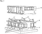
- A denotes a moveable upper tool part
- B a holder part supported by gas-filled springs
- D four movement controlling linkage devices according to the invention fitted to a holder.
- a lower push rod 2, likewise displaceably supported in the housing 20, is substantially parallel with the push rod 1 and operatively engages by way of a roller 9 with the linkage arm 5b of the linkage arm 5.
- the lower push rod 2 is designed to be acted upon by springs of the holder part B and its displacement distance corresponds to a distance over which the holder part B must be brought from its basic position at largely the same speed as the upper tool part A has at the start of a deep-drawing operation or other sheet metal working operation.
- the upper push rod 1 is designed to be acted upon by the upper tool part A and its function, under the said action, is to produce an adjustment of the linkage arms 3 and 5 in such a way that the action of the upper tool part A on the holder part B imparts an acceleration to the latter, which is largely constant from the basic position until the start of the deep-drawing operation, which means that at the latter instant/position the upper tool part A and the holder part B have largely the same speed.
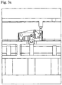
- Figure 3a shows the said basic position, in which the press upper part A is situated a distance above the holder part B.
- an acceleration of the holder part B commences, so that this has a speed approximately equal to the speed of the press upper part A1, when the full force of the press upper part A1 acts on the holder B.
- this See also the movement of the press upper part A1 and the holder B together with piston rods D1 of the gas-filled springs D from the position shown in figures 3c to 3d .
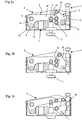
- this therefore shows the basic position, in which the support 2 is rigid or locked to the linkage mechanism 5.
- Figure 2c shows the "final position" of the linkage device E in the depression of the holder B, that is to say a position in which the linkage device E is rigid.
- the linkage device has here therefore completed its holder acceleration function and is now ready, on completion of the working operation, to brake the upward movement of the holder in the limit position of the gas-filled spring pistons entirely mechanically, in such a way that the linkage device functions inversely and gives a very slow outward movement of the support 2 on completion of the return movement and is thereby capable of maintaining a constant contact with the holder B.
- the primary function of the gas-filled spring 7 is to return the linkage mechanisms of the linkage device E to the basic position shown in figure 3 a.
- Figures 3 a to 3d show positions largely corresponding to the positions of the linkage device E, press upper part A1 and holder B during the pressing process, as shown in figures 2a to 2c .
- Figure 4a and 4b respectively show diagrams of the acceleration and speed of the holder.
- the linkage mechanisms 3 and 5 that is to say the lengths of the lever arms and mutual points of articulation
- the holder acceleration can be designed so as to achieve the earlier speed matching with the upper press part A.
- Figures 5a and 5b respectively show diagrams of the movement of the press upper part and the force exerted on the plate holder without the use of a movement-controlling arrangement according to the invention.
- Figure 5a clearly shows that a heavy impact loading occurs when the press upper part encounters the holder, just as lifting of the holder occurs at the end of the press cycle.
- Figures 6a and 6b show how the impact loading is however at least reduced by the use of a method/arrangement according to the invention.
Landscapes
- Engineering & Computer Science (AREA)
- Mechanical Engineering (AREA)
- Presses And Accessory Devices Thereof (AREA)
- Shaping Metal By Deep-Drawing, Or The Like (AREA)
- Press Drives And Press Lines (AREA)
Description
- The present invention relates to a sheet metal working tool according to the pre-characterising clause of
claim 1. - The use of a tool and fabrication holder mounted in a press is known in sheet metal forming operations. Certain parts of the tool follow the movement of the press slide, while other parts are at rest during a part of the press cycle. One example is where a sheet metal holder is used, which rests on springs, which exert the sheet metal holding force. Other examples of moveable tool parts are shuttles and punches. The springs, at least three in number, are at rest until the upper tool part impacts against the holder and moves this downwards, the springs being tensioned. A direct impact on a stationary sheet metal holder places heavy stresses on the tool and on mechanical parts of the press, whilst unwanted noise and vibrations are generated. An excessive impact between the upper tool part and the sheet metal holder also has a negative effect on the sheet metal forming process itself, since the sheet metal fabrication that is to be formed is situated between upper tool and sheet metal holder, and since there is a risk of the sheet metal lubrication film breaking down, which carries a risk of irregular quality in the subsequent sheet metal drawing process.
- After the pressing process, the holder with finish-formed sheet metal part is brought into its original position by the springs returning to their extended standby position. Because a certain return speed is imparted to the holder by the springs, there is a risk that the holder will not stop immediately when the springs reach their limit position, but will continue until the g-force has braked the speed. There is a risk here that both holder and fabrication will lift off entirely from the springs. This "lifting" of the fabrication and the holder causes wear and creates noise. There is also a risk of the holder itself jumping out of its guides.
- Attempts have previously been made to solve the aforementioned problem by the use of CNC hydraulic systems or by reducing the impact stresses and the fabrication and holder lifting through the use of separate dampers. The disadvantage of CNC hydraulic systems is the need for a separate hydraulic source and cooling facility for the hydraulic fluid used. Connecting hoses are required. Energy losses occur during acceleration and retardation. Moreover, such a system is relatively complicated and expensive. Damping the impact through the use of separate dampers likewise has disadvantages, partly due to the generation of heat and partly due to the fact that the damping function does not vary according to the pressing speed. Known damping arrangements are often temperature-sensitive and also sensitive to mechanical effects.
- A design construction for initiating an downward movement of a fabrication holder is specified in
EP 1 034 858 A2 - As an example of the prior art, reference will also be made to
DE 3623188 C1 , on the basis of which the pre-characterising clause of the independent claim has been worded. - The object of the present invention is to provide a sheet metal working tool of the type referred to in the introductory part, by means of which the aforementioned disadvantages in respect of the noise generated and the wear to the pressing tool are at least reduced. In the sheet metal working tool according to the invention this is achieved as set forth in the characterising part of
claim 1. The invention furthermore adjusts the movement between holder and upper tool part without any significant energy losses occurring and whilst at the same time ensuring a correct working process for the sheet metal fabrication. In addition, sheet metal working tool according to the invention permits an increase in the working speed without an increased risk of the holder and the sheet metal fabrication coming loose from one another. - The invention is easily applicable and can be fitted to the holder of existing working tools, that is to say in the tool part that is to be accelerated and retarded, and which can easily be removed for maintenance without the need to dismantle any other tool components, and which, moreover, takes up little space and requires a minimum of maintenance.
- The invention furthermore provides a mechanical linkage device, in which a built-in gas-filled spring is capable of accumulating a proportion of the kinetic energy of the press slide during a controlled acceleration of the holder with sheet metal fabrication prior to the actual working process. The gas-filled spring then releases this energy in order to return the mechanical linkage device and the holder before the next sheet metal working process, the kinetic energy being restored to the press slide.
- The invention provides a sheet metal working tool in which the mechanical linkage device is so arranged that the acceleration of the holder with sheet metal fabrication occurs primarily before the gas-filled springs, supporting the holder and returning the sheet metal fabrication, start to be compressed during the working stage. This naturally reduces the load on the sheet metal working tool according to the invention.
- The invention therefore achieves control over the movement of the holder, this control being directly linked to the position of the press upper part, which means that a parallel movement is imparted to the holder irrespective of the load thereon.
- The invention will now be explained in more detail with reference to an application in a press shown in the drawings attached. The person skilled in the art will appreciate that the invention, as already stated in the introductory part, can also be adapted to other sheet metal working tools, in connection with punching or cutting, for example, so that the following description must only be regarded as an example of the applicability of the invention.
- In the drawing:
-
Figure 1 shows a diagrammatic perspective view of a moveable press upper part, a sheet-metal fabrication holder supported by gas-filled springs and four movement-controlling linkage devices according to the invention located directly on the holder and shown in a standby position for pre-acceleration of the sheet metal holder, -
Figures 2a to 2c show successive activation positions of the movement-controlling linkage device in the acceleration of sheet metal holder and sheet metal fabrication, -
Figures 3a to 3d show different positions of the press upper part, sheet metal holder and gas-filled springs in a pressing process corresponding to the linkage device positions shown infigures 2a to 2c . -
Figures 4a and 4b are diagrams respectively showing the acceleration and speed of the holder as a function of the time. -
Figures 5a-5b are schematic diagrams respectively showing the movement of the press parts and the force exerted on the sheet metal holder without any use of any movement-controlling arrangement,
and -
Figures 6a-6b are schematic diagrams corresponding tofigures 5a-5b respectively showing the movement of the press upper part and the holder, and the force exerted on the sheet metal holder, using a movement control according to the present invention. - In
figure 1 , A denotes a moveable upper tool part, B a holder part supported by gas-filled springs D, and E four movement controlling linkage devices according to the invention fitted to a holder. - An embodiment and the function of the arrangement according to the invention denoted by E will now be explained with reference to
figures 2a to 2c . Ahousing 20, connected to the holder part B, contains a generallyangled linkage arm 5, which is capable of rotating about anaxis 6, one (short)leg 5a of which engages by way of aroller 8 with apiston rod 7a of a gas-filledspring 7, and the other (longer)leg 5b of which is connected by way of alink 10 to the oneleg 3b of alinkage arm 3, which is rotatable about anaxis 4 and is operatively connected by way of aroller 3a and astop 1a to anupper push rod 1 displaceably supported in thehousing 20. Alower push rod 2, likewise displaceably supported in thehousing 20, is substantially parallel with thepush rod 1 and operatively engages by way of aroller 9 with thelinkage arm 5b of thelinkage arm 5. - The
lower push rod 2 is designed to be acted upon by springs of the holder part B and its displacement distance corresponds to a distance over which the holder part B must be brought from its basic position at largely the same speed as the upper tool part A has at the start of a deep-drawing operation or other sheet metal working operation. - The
upper push rod 1 is designed to be acted upon by the upper tool part A and its function, under the said action, is to produce an adjustment of thelinkage arms - It will be seen from
figures 2a to 2c how thelinkage arms -
Figure 3a shows the said basic position, in which the press upper part A is situated a distance above the holder part B. When theupper push rod 1 of the linkage device E comes to bear against the descending press upper part A, an acceleration of the holder part B commences, so that this has a speed approximately equal to the speed of the press upper part A1, when the full force of the press upper part A1 acts on the holder B. See also the movement of the press upper part A1 and the holder B together with piston rods D1 of the gas-filled springs D from the position shown infigures 3c to 3d . Returning tofigure 2a , this therefore shows the basic position, in which thesupport 2 is rigid or locked to thelinkage mechanism 5. Only when theupper push rod 1 has reached the position shown infigure 2b , which occurs due to the fact that astop 1a on thepush rod 1 acts on theroller 3a on thelinkage mechanism 3, which is articulated to thejoint 4. Continued depression of thepush rod 1 is partially damped by the gas-filledspring 7 through movement of thelinkage mechanism 5, which is rotated about theaxis 6 and presses in the piston of the gas-filled spring by way of theroller 8. Thesupport part 2 is all the time in contact, via theroller device 9, with thesecond linkage part 5 in close proximity to the said one end of thelinkage part 5, in order to ensure that the movement of the holder B is linked to the speed of the press upper part A.Figure 2c shows the "final position" of the linkage device E in the depression of the holder B, that is to say a position in which the linkage device E is rigid. The linkage device has here therefore completed its holder acceleration function and is now ready, on completion of the working operation, to brake the upward movement of the holder in the limit position of the gas-filled spring pistons entirely mechanically, in such a way that the linkage device functions inversely and gives a very slow outward movement of thesupport 2 on completion of the return movement and is thereby capable of maintaining a constant contact with the holder B. The primary function of the gas-filledspring 7 is to return the linkage mechanisms of the linkage device E to the basic position shown infigure 3 a. -
Figures 3 a to 3d show positions largely corresponding to the positions of the linkage device E, press upper part A1 and holder B during the pressing process, as shown infigures 2a to 2c . -
Figure 4a and 4b respectively show diagrams of the acceleration and speed of the holder. Through a suitable choice of thelinkage mechanisms 3 and 5 (infigure 2a ), that is to say the lengths of the lever arms and mutual points of articulation, the holder acceleration can be designed so as to achieve the earlier speed matching with the upper press part A. -
Figures 5a and 5b respectively show diagrams of the movement of the press upper part and the force exerted on the plate holder without the use of a movement-controlling arrangement according to the invention.Figure 5a clearly shows that a heavy impact loading occurs when the press upper part encounters the holder, just as lifting of the holder occurs at the end of the press cycle.Figures 6a and 6b show how the impact loading is however at least reduced by the use of a method/arrangement according to the invention. - The invention is not limited to the example of an embodiment described above but lends itself to modifications within the scope of the claims specified below.
Claims (10)
- A sheet metal working tool comprising
a lower and an upper (A) moveable tool part and a holder part (B) that are designed, during a sheet metal working operation in which a sheet metal fabrication is subjected to working between said tool parts, to hold said sheet metal fabrication part to said upper moveable tool part (A) in a working position by spring elements (D) supporting said holder part (B), and also linkage devices (E) that are designed to impart a speed component to said holder part (B),
characterised in that each of said linkage devices (E) comprises:a housing (20), anda system of interconnected and articulated links (3, 5, 10), connected to said holder part (B), of which one linkage arm (3) is designed to be acted upon by the movement of said upper movable tool part (A), creating a power-transmitting operative connection between said upper moveable tool part (A) and said holder part (B),a generally angled linkage arm (5) having one of its legs (5b) connected by way of a link (10) to a leg (3b) of said linkage arm (3),said leg (5b) of said generally angled linkage arm (5) engaging a lower push rod (2), which in turn is designed to be acted upon by springs (D) of said holder part (B),said power-transmitting operative connection being analogous to a single linkage arm, the length of which varies over time, so that from a standstill in a basic position said holder part (B) has substantially the same speed as said upper moveable tool part (A) in a starting position, and a corresponding retardation in a subsequent ascending movement. - Tool according to claim 1, wherein said linkage device (E) is fixed solely to said holder part (B).
- Tool according to any of the preceding claims, wherein each of said linkage devices (E) comprise a push rod (1) designed to be acted upon by said upper movable tool part (A), said push rod (1) comprising a stop (1a) acting on a roller (3a) on said linkage mechanism (3), which is articulated to a joint (4) in said housing (20).
- Tool according to any of the preceding claims, wherein each of said linkage devices (E) comprise a linkage arm(3), a link (10) and a generally angled linkage arm (5), wherein one leg (5b) of said generally angled linkage arm (5), capable of rotating about an axis (6), is connected by way of said link (10) to a leg (3b) of said linkage arm (3), said linkage arm (3) being rotatable about an axis (4), said leg (5b) of said linkage arm (5) being operatively engaged by way of a roller (9) with a push rod (2), wherein said push rod (2) all the time is in contact with said linkage arm (5) in order to ensure that the movement of said holder (B) is linked to the speed of said upper moveable part (A), and wherein said push rod (2) is designed to be acted upon by springs (D).
- Tool according to any of the preceding claims, wherein said linkage device (E) comprises an energy-storing element (7) designed to store mechanical energy during movement of said holder part (B) from said basic position to said working position, and designed thereafter to release said stored energy to reverse the movement of said holder part (B) from said working position to said basic position.
- Tool according to claim 5, wherein said energy-storing element (7) comprises a gas-filled spring.
- Tool according to any of the preceding claims, wherein a piston rod (7a) of said gas-filled spring (7) is designed to engage by way of a roller (8) with a leg (5a) of said linkage arm (5), wherein depression of said push rod (1) is partially dampened by said gas-filled spring (7) through movement of said linkage arm (5), wherein said gas-filled spring (7) returns the linkage mechanisms (3, 5, 10) of the linkage device (E) to the basic position.
- Tool according to any of the preceding claims, wherein at least one of said linkage devices (E) is designed to be acted upon by said upper movable tool part (A) over a moving distance between said basic position and said starting position for the working operation, over which distance the majority of said supporting spring elements (D) are inoperative.
- Tool according to claim 1, wherein said linkage device (E) comprises a mechanical transmission device (E) arranged in said sheet metal holder (B) and having a push rod (1) actuatable by said upper moveable tool part (A), a stop (1a) on said push rod (1) being designed to act on a roller device (3a) arranged in said linkage arm (3), which is articulated about a first joint (4) in said transmission device (E), said linkage arm (3) being connected to one end of said second linkage part (5), which is articulated about a second joint (6) and the other end of which interacts with the piston rod of a spring mechanism (7), said push rod (2), by way of a roller device (9), engaging throughout with said second linkage part (5) closely adjacent to said one end of said second linkage part (5).
- Tool according to any of the preceding claims, comprising said push rod (2) and said roller device (9), said roller (9) operatively engaged by said leg (5b) of said linkage arm (5) to cause said push rod (2) to move between an extended and retracted position.
Applications Claiming Priority (3)
| Application Number | Priority Date | Filing Date | Title |
|---|---|---|---|
| SE0101928A SE0101928D0 (en) | 2001-05-31 | 2001-05-31 | Procedure and apparatus for pressing tools |
| SE0101928 | 2001-05-31 | ||
| PCT/SE2002/001046 WO2002096580A1 (en) | 2001-05-31 | 2002-05-31 | A method and a device for reducing the noise level at a deep-drawing press |
Publications (2)
| Publication Number | Publication Date |
|---|---|
| EP1390165A1 EP1390165A1 (en) | 2004-02-25 |
| EP1390165B1 true EP1390165B1 (en) | 2017-03-08 |
Family
ID=20284317
Family Applications (1)
| Application Number | Title | Priority Date | Filing Date |
|---|---|---|---|
| EP02736375.3A Expired - Lifetime EP1390165B1 (en) | 2001-05-31 | 2002-05-31 | Sheet metal-working tool |
Country Status (5)
| Country | Link |
|---|---|
| US (1) | US7124614B2 (en) |
| EP (1) | EP1390165B1 (en) |
| JP (1) | JP4320771B2 (en) |
| SE (1) | SE0101928D0 (en) |
| WO (1) | WO2002096580A1 (en) |
Families Citing this family (6)
| Publication number | Priority date | Publication date | Assignee | Title |
|---|---|---|---|---|
| SE0201597L (en) | 2002-05-29 | 2003-10-21 | Alfa Laval Corp Ab | Flat heat exchanger device and heat exchanger plate |
| SE526302C2 (en) * | 2004-10-01 | 2005-08-16 | Stroemsholmen Ab | Impact plate and plate forming tool including such impact plate |
| JP2006142308A (en) * | 2004-11-16 | 2006-06-08 | Umix Co Ltd | Diaphragm stabilizer and its stabilizer unit |
| US8696739B2 (en) * | 2008-08-29 | 2014-04-15 | Cook Medical Technologies Llc | Barbed anchor |
| FR3069177B1 (en) * | 2017-07-21 | 2020-10-23 | Psa Automobiles Sa | STAMPING PRESS INCLUDING A COMPRESSION SPRING |
| WO2019111386A1 (en) * | 2017-12-07 | 2019-06-13 | 日本製鉄株式会社 | Press die |
Family Cites Families (5)
| Publication number | Priority date | Publication date | Assignee | Title |
|---|---|---|---|---|
| DE3623188C1 (en) * | 1986-07-10 | 1987-09-10 | Daimler Benz Ag | Working method for the deep-drawing of metal sheets, and a deep-drawing press which carries out this method |
| SE9401119L (en) * | 1994-03-31 | 1995-03-20 | Stromsholmens Mek Verkstad | Device for a piston-cylinder gas spring |
| CA2237509C (en) * | 1998-05-11 | 2006-06-27 | Umix Co., Ltd. | Structure for a drawing die and a run-up unit therefor |
| JP3181888B2 (en) * | 1999-03-09 | 2001-07-03 | ユミックス株式会社 | Quiet structure of processing machine, quiet structure of press machine, silent type of drawing type and its silent run-up unit |
| US6491143B1 (en) | 1999-12-30 | 2002-12-10 | Diebolt International, Inc. | Low impact gas spring |
-
2001
- 2001-05-31 SE SE0101928A patent/SE0101928D0/en unknown
-
2002
- 2002-05-31 EP EP02736375.3A patent/EP1390165B1/en not_active Expired - Lifetime
- 2002-05-31 US US10/479,143 patent/US7124614B2/en not_active Expired - Lifetime
- 2002-05-31 WO PCT/SE2002/001046 patent/WO2002096580A1/en not_active Ceased
- 2002-05-31 JP JP2002593082A patent/JP4320771B2/en not_active Expired - Lifetime
Non-Patent Citations (1)
| Title |
|---|
| None * |
Also Published As
| Publication number | Publication date |
|---|---|
| US20040250595A1 (en) | 2004-12-16 |
| SE0101928D0 (en) | 2001-05-31 |
| WO2002096580A1 (en) | 2002-12-05 |
| JP4320771B2 (en) | 2009-08-26 |
| US7124614B2 (en) | 2006-10-24 |
| EP1390165A1 (en) | 2004-02-25 |
| JP2004522593A (en) | 2004-07-29 |
Similar Documents
| Publication | Publication Date | Title |
|---|---|---|
| US20080127839A1 (en) | Press with travel controllable drive arrangement | |
| US7124614B2 (en) | Method and a device for reducing the noise level at a deep-drawing press | |
| US6919555B2 (en) | Guard device for machines such as bending presses, cutting machines, stamping machines or the like | |
| JPH0422649B2 (en) | ||
| AU2019383850B2 (en) | A pile driving system | |
| US4378900A (en) | Machine with fingerguard | |
| US7258030B2 (en) | Failsafe element for rotary cam unit used in a flanged die | |
| EP0956913B1 (en) | Drawing die and press die with a noise reducing device | |
| US4434639A (en) | Arrangement for producing drawn formations on workpieces, particularly in a cutting and pressing machine | |
| EP1549582B1 (en) | Combined elevator guiding and safety braking device | |
| EP1034858B1 (en) | Processing machine including noise-reducing structure | |
| JP3195411B2 (en) | Equipment for tool magazine of thin plate machine tools | |
| KR20070061426A (en) | Sewing machine | |
| EP0008906B1 (en) | Load multiplying mechanisms | |
| JPH0985498A (en) | Cam for press die | |
| WO2003082723A1 (en) | Elevator buffer | |
| EP0870114B1 (en) | Arrangement in a pressing tool for sheet metal forming | |
| JP3968806B2 (en) | Cam for press mold | |
| EP0515835A2 (en) | Apparatus and method for disposing wasted cans | |
| JPH08323420A (en) | Forming die for sheet metal | |
| US5110026A (en) | Apparatus for a stepwise advancing of a web-shaped workpiece | |
| US4210013A (en) | Press with load transfer mechanism | |
| JP3736277B2 (en) | Dowel molding unit | |
| US3111062A (en) | Means for controlling hydraulic cylinders and like actuators | |
| KR200188001Y1 (en) | Atc magazine actuating device |
Legal Events
| Date | Code | Title | Description |
|---|---|---|---|
| PUAI | Public reference made under article 153(3) epc to a published international application that has entered the european phase |
Free format text: ORIGINAL CODE: 0009012 |
|
| 17P | Request for examination filed |
Effective date: 20031020 |
|
| AK | Designated contracting states |
Kind code of ref document: A1 Designated state(s): AT BE CH CY DE DK ES FI FR GB GR IE IT LI LU MC NL PT SE TR |
|
| AX | Request for extension of the european patent |
Extension state: AL LT LV MK RO SI |
|
| 17Q | First examination report despatched |
Effective date: 20091012 |
|
| GRAP | Despatch of communication of intention to grant a patent |
Free format text: ORIGINAL CODE: EPIDOSNIGR1 |
|
| STAA | Information on the status of an ep patent application or granted ep patent |
Free format text: STATUS: GRANT OF PATENT IS INTENDED |
|
| INTG | Intention to grant announced |
Effective date: 20161124 |
|
| RIN1 | Information on inventor provided before grant (corrected) |
Inventor name: CRONHOLM, MARCUS Inventor name: AXELSSON, JACOB |
|
| GRAS | Grant fee paid |
Free format text: ORIGINAL CODE: EPIDOSNIGR3 |
|
| GRAA | (expected) grant |
Free format text: ORIGINAL CODE: 0009210 |
|
| STAA | Information on the status of an ep patent application or granted ep patent |
Free format text: STATUS: THE PATENT HAS BEEN GRANTED |
|
| AK | Designated contracting states |
Kind code of ref document: B1 Designated state(s): AT BE CH CY DE DK ES FI FR GB GR IE IT LI LU MC NL PT SE TR |
|
| REG | Reference to a national code |
Ref country code: GB Ref legal event code: FG4D |
|
| REG | Reference to a national code |
Ref country code: CH Ref legal event code: EP Ref country code: AT Ref legal event code: REF Ref document number: 873069 Country of ref document: AT Kind code of ref document: T Effective date: 20170315 |
|
| REG | Reference to a national code |
Ref country code: IE Ref legal event code: FG4D |
|
| REG | Reference to a national code |
Ref country code: FR Ref legal event code: PLFP Year of fee payment: 16 |
|
| REG | Reference to a national code |
Ref country code: DE Ref legal event code: R096 Ref document number: 60248716 Country of ref document: DE |
|
| REG | Reference to a national code |
Ref country code: NL Ref legal event code: MP Effective date: 20170308 |
|
| PG25 | Lapsed in a contracting state [announced via postgrant information from national office to epo] |
Ref country code: GR Free format text: LAPSE BECAUSE OF FAILURE TO SUBMIT A TRANSLATION OF THE DESCRIPTION OR TO PAY THE FEE WITHIN THE PRESCRIBED TIME-LIMIT Effective date: 20170609 Ref country code: FI Free format text: LAPSE BECAUSE OF FAILURE TO SUBMIT A TRANSLATION OF THE DESCRIPTION OR TO PAY THE FEE WITHIN THE PRESCRIBED TIME-LIMIT Effective date: 20170308 |
|
| REG | Reference to a national code |
Ref country code: AT Ref legal event code: MK05 Ref document number: 873069 Country of ref document: AT Kind code of ref document: T Effective date: 20170308 |
|
| PG25 | Lapsed in a contracting state [announced via postgrant information from national office to epo] |
Ref country code: LU Free format text: LAPSE BECAUSE OF NON-PAYMENT OF DUE FEES Effective date: 20170531 Ref country code: ES Free format text: LAPSE BECAUSE OF FAILURE TO SUBMIT A TRANSLATION OF THE DESCRIPTION OR TO PAY THE FEE WITHIN THE PRESCRIBED TIME-LIMIT Effective date: 20170308 Ref country code: SE Free format text: LAPSE BECAUSE OF FAILURE TO SUBMIT A TRANSLATION OF THE DESCRIPTION OR TO PAY THE FEE WITHIN THE PRESCRIBED TIME-LIMIT Effective date: 20170308 |
|
| PG25 | Lapsed in a contracting state [announced via postgrant information from national office to epo] |
Ref country code: NL Free format text: LAPSE BECAUSE OF FAILURE TO SUBMIT A TRANSLATION OF THE DESCRIPTION OR TO PAY THE FEE WITHIN THE PRESCRIBED TIME-LIMIT Effective date: 20170308 |
|
| PG25 | Lapsed in a contracting state [announced via postgrant information from national office to epo] |
Ref country code: AT Free format text: LAPSE BECAUSE OF FAILURE TO SUBMIT A TRANSLATION OF THE DESCRIPTION OR TO PAY THE FEE WITHIN THE PRESCRIBED TIME-LIMIT Effective date: 20170308 Ref country code: IT Free format text: LAPSE BECAUSE OF FAILURE TO SUBMIT A TRANSLATION OF THE DESCRIPTION OR TO PAY THE FEE WITHIN THE PRESCRIBED TIME-LIMIT Effective date: 20170308 |
|
| PG25 | Lapsed in a contracting state [announced via postgrant information from national office to epo] |
Ref country code: PT Free format text: LAPSE BECAUSE OF FAILURE TO SUBMIT A TRANSLATION OF THE DESCRIPTION OR TO PAY THE FEE WITHIN THE PRESCRIBED TIME-LIMIT Effective date: 20170710 |
|
| REG | Reference to a national code |
Ref country code: DE Ref legal event code: R097 Ref document number: 60248716 Country of ref document: DE |
|
| REG | Reference to a national code |
Ref country code: CH Ref legal event code: PL |
|
| PLBE | No opposition filed within time limit |
Free format text: ORIGINAL CODE: 0009261 |
|
| STAA | Information on the status of an ep patent application or granted ep patent |
Free format text: STATUS: NO OPPOSITION FILED WITHIN TIME LIMIT |
|
| PG25 | Lapsed in a contracting state [announced via postgrant information from national office to epo] |
Ref country code: MC Free format text: LAPSE BECAUSE OF FAILURE TO SUBMIT A TRANSLATION OF THE DESCRIPTION OR TO PAY THE FEE WITHIN THE PRESCRIBED TIME-LIMIT Effective date: 20170308 Ref country code: DK Free format text: LAPSE BECAUSE OF FAILURE TO SUBMIT A TRANSLATION OF THE DESCRIPTION OR TO PAY THE FEE WITHIN THE PRESCRIBED TIME-LIMIT Effective date: 20170308 |
|
| 26N | No opposition filed |
Effective date: 20171211 |
|
| REG | Reference to a national code |
Ref country code: IE Ref legal event code: MM4A |
|
| GBPC | Gb: european patent ceased through non-payment of renewal fee |
Effective date: 20170608 |
|
| PG25 | Lapsed in a contracting state [announced via postgrant information from national office to epo] |
Ref country code: CH Free format text: LAPSE BECAUSE OF NON-PAYMENT OF DUE FEES Effective date: 20170531 Ref country code: LI Free format text: LAPSE BECAUSE OF NON-PAYMENT OF DUE FEES Effective date: 20170531 |
|
| REG | Reference to a national code |
Ref country code: FR Ref legal event code: PLFP Year of fee payment: 17 |
|
| REG | Reference to a national code |
Ref country code: BE Ref legal event code: MM Effective date: 20170531 |
|
| PG25 | Lapsed in a contracting state [announced via postgrant information from national office to epo] |
Ref country code: IE Free format text: LAPSE BECAUSE OF NON-PAYMENT OF DUE FEES Effective date: 20170531 Ref country code: GB Free format text: LAPSE BECAUSE OF NON-PAYMENT OF DUE FEES Effective date: 20170608 |
|
| PG25 | Lapsed in a contracting state [announced via postgrant information from national office to epo] |
Ref country code: BE Free format text: LAPSE BECAUSE OF NON-PAYMENT OF DUE FEES Effective date: 20170531 |
|
| PG25 | Lapsed in a contracting state [announced via postgrant information from national office to epo] |
Ref country code: CY Free format text: LAPSE BECAUSE OF NON-PAYMENT OF DUE FEES Effective date: 20170308 |
|
| PG25 | Lapsed in a contracting state [announced via postgrant information from national office to epo] |
Ref country code: TR Free format text: LAPSE BECAUSE OF FAILURE TO SUBMIT A TRANSLATION OF THE DESCRIPTION OR TO PAY THE FEE WITHIN THE PRESCRIBED TIME-LIMIT Effective date: 20170308 |
|
| PGFP | Annual fee paid to national office [announced via postgrant information from national office to epo] |
Ref country code: DE Payment date: 20210419 Year of fee payment: 20 Ref country code: FR Payment date: 20210421 Year of fee payment: 20 |
|
| REG | Reference to a national code |
Ref country code: DE Ref legal event code: R071 Ref document number: 60248716 Country of ref document: DE |