EP1034858A2 - Silent structure of processing machine, silent structure of pressing machine, silent structure of drawing die, and silent run-up unit thereof - Google Patents
Silent structure of processing machine, silent structure of pressing machine, silent structure of drawing die, and silent run-up unit thereof Download PDFInfo
- Publication number
- EP1034858A2 EP1034858A2 EP99105848A EP99105848A EP1034858A2 EP 1034858 A2 EP1034858 A2 EP 1034858A2 EP 99105848 A EP99105848 A EP 99105848A EP 99105848 A EP99105848 A EP 99105848A EP 1034858 A2 EP1034858 A2 EP 1034858A2
- Authority
- EP
- European Patent Office
- Prior art keywords
- die
- run
- lever
- thin plate
- blank holder
- Prior art date
- Legal status (The legal status is an assumption and is not a legal conclusion. Google has not performed a legal analysis and makes no representation as to the accuracy of the status listed.)
- Granted
Links
Images



Classifications
-
- B—PERFORMING OPERATIONS; TRANSPORTING
- B21—MECHANICAL METAL-WORKING WITHOUT ESSENTIALLY REMOVING MATERIAL; PUNCHING METAL
- B21D—WORKING OR PROCESSING OF SHEET METAL OR METAL TUBES, RODS OR PROFILES WITHOUT ESSENTIALLY REMOVING MATERIAL; PUNCHING METAL
- B21D24/00—Special deep-drawing arrangements in, or in connection with, presses
-
- B—PERFORMING OPERATIONS; TRANSPORTING
- B21—MECHANICAL METAL-WORKING WITHOUT ESSENTIALLY REMOVING MATERIAL; PUNCHING METAL
- B21D—WORKING OR PROCESSING OF SHEET METAL OR METAL TUBES, RODS OR PROFILES WITHOUT ESSENTIALLY REMOVING MATERIAL; PUNCHING METAL
- B21D24/00—Special deep-drawing arrangements in, or in connection with, presses
- B21D24/10—Devices controlling or operating blank holders independently, or in conjunction with dies
- B21D24/14—Devices controlling or operating blank holders independently, or in conjunction with dies pneumatically or hydraulically
-
- B—PERFORMING OPERATIONS; TRANSPORTING
- B21—MECHANICAL METAL-WORKING WITHOUT ESSENTIALLY REMOVING MATERIAL; PUNCHING METAL
- B21D—WORKING OR PROCESSING OF SHEET METAL OR METAL TUBES, RODS OR PROFILES WITHOUT ESSENTIALLY REMOVING MATERIAL; PUNCHING METAL
- B21D22/00—Shaping without cutting, by stamping, spinning, or deep-drawing
- B21D22/20—Deep-drawing
- B21D22/22—Deep-drawing with devices for holding the edge of the blanks
-
- B—PERFORMING OPERATIONS; TRANSPORTING
- B30—PRESSES
- B30B—PRESSES IN GENERAL
- B30B15/00—Details of, or accessories for, presses; Auxiliary measures in connection with pressing
- B30B15/0076—Noise or vibration isolation means
Definitions
- the present invention relates to a silent structure of a processing machine, a silent structure of a pressing machine, a silent structure of a pressing die, and more particularly, to a silent structure of a drawing die and a silent run-up unit thereof used when a metal plate part such as an automobile or an electric home appliance is subjected to a drawing working.
- Fig.9 shows one example of the drawing die.
- the drawing die comprises a punch 101 located at a central position of the drawing die, a blank holder 103 fitted around the punch 101 and vertically movably supported by a cushion pin 102, and a die 104 disposed such as to oppose the punch 101 for vertical movement.
- the reference number 105 represents an air vent.
- a lower die 109 comprising the punch 101 and the blank holder 103 is fixed to a bolster 106 of a pressing machine, and an upper die 110 comprising the die 104 is fixed to a ram 107 of the pressing machine.
- the upper die 110 moves vertically by driving the pressing machine.
- the blank holder 103 is supported by the cushion pin 102, the cushion pin 102 is moved vertically by a cushion device of the pressing machine and with this movement, the blank holder 103 is also moved vertically.
- a thin plate 108 is placed on the blank holder 103 and the punch 101 as shown with the phantom lines.
- the die 104 collides against the thin plate 108 on the blank holder 103 around the entire outer periphery of the punch 101 so that the thin plate 108 is sandwiched between the blank holder 103 and the die 104. Subsequently, if the upper die 110 is lowered, the thin plate 108 sandwiched between the blank holder 103 and the die 104 is drawn by the punch 101, and when the upper die 110 reaches the bottom dead center, the thin plate 108 is drawn into a work W.
- the blank holder 103 is moved up to the position shown with the phantom lines by the ascending force of the cushion pin 102, and the work W is removed from the punch 101.
- the die 104 of the upper die 110 is provided with the air vent 105 so that the negative pressure is prevented from being generated between the work W and the die 104 when the work W is dropped by its own weight.
- the work W may be moved downward by a push pin (not shown) biased by a spring, thereby removing the work W from the die 104.
- the work W removed from the pressing machine is transferred to the a pressing machine of the next step.
- the pressing machine is surrounded by a soundproof wall.
- an opening must be formed in the soundproof wall for bringing in and out the work from and to the pressing machine and thus, the noise leaks from the opening.
- an operator working in the vicinity of the pressing machine surrounded by the soundproof wall is bothered by the great noise.
- a noise of a pressing machine having a pressing die, and noises of other processing machine for metal or resin are also regarded as a social problem.
- a silent structure of a processing machine comprising a stationary bed, a movable member vertically movable with respect to the bed, a pad of a cushion device located below the bed for biasing a cushion pin upward, wherein the stationary member is rotatably provided with a run-up lever, the movable member facing the run-up lever is vertically provided with an operation cam, the operation cam acts on the run-up lever before mounted working tools sandwich a work, and the pad is allowed to run up.
- a silent structure of a pressing machine comprising a stationary bed, a ram vertically movable with respect to the bed, a pad of a cushion device located below the bed for biasing a cushion pin upward, wherein the stationary member is rotatably provided with a run-up lever, the ram facing the run-up lever is vertically provided with an operation cam, the operation cam acts on the run-up lever before mounted pressing dies sandwich a thin plate or a work, and the pad is allowed to run up.
- a silent structure of a drawing die comprising a punch, a blank holder fitted around the punch and vertically movably supported by a cushion pin, and a vertically movable die disposed such as to face the punch, a thin plate being placed on a blank holder which is moved up by the cushion pin, the die being lowered, thereby sandwiching the thin plate between the blank holder and the die for drawing the thin plate by the punch, wherein a lower base plate is rotatably provided with a run-up lever for pushing the blank holder for allowing the latter to run up before the die collides against the thin plate, an operation cam for driving the run-up lever is disposed at a position on the die facing the run-up lever, and the die collides against the thin plate on the blank holder after the blank holder runs up.
- the operation cam has a cam surface a tilt angle for changing speed.
- a silent run-up unit having a run-up lever and an operation cam for driving the run-up lever.
- a silent structure of a pressing die comprises a lower die provided with an operation cam, and an upper die provided at its position facing the operation cam with a run-up lever. Therefore, it can be expected that the noise is reduced.
- the thin plate or the work is allowed to run up before the thin plate or the work is sandwiched. Therefore, it can be expected that the noise of the pressing die is reduced.
- a lower die 1 comprises a punch 2, and a blank holder 4 vertically movably fitted around the punch 2 and supported by a cushion pin 3.
- the reference number 7 represents a lower die base plate integrally formed with an outer periphery of the punch 2.
- An upper die 5 comprises a die 6 disposed such as to be opposed to the punch 2.
- a silent run-up unit is mounted to the lower die base plate 7 and the die 6 for allowing the blank holder 4 to run up.
- One example thereof is illustrated.
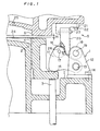
- a substantially triangle run-up lever 11 for pushing the blank holder 3 for allowing the latter to run up is rotatably provided around a center shaft 13 of a bracket 12.
- the bracket 12 is fixed to the lower die base plate 7 by a bolt 14.
- the run-up lever 11 is rotatably provided around the center shaft 13 provided on the bracket 12 such that the run-up lever 11 pushes a flange 15 of the blank holder 4.
- a roller 16 is rotatably provided around a supporting shaft 17 on an upper portion of the run-up lever 11, and another roller 18 is rotatably provided around a supporting shaft 19 on the bracket 12 at a position opposed to the roller 16.
- An operation cam 20 is provided on the die 6 at a position between the rollers 16 and 18.
- This operation cam 20 is mounted to the die 6 through a supporting mount 21.
- the supporting mount 21 is fixed to the die 6 by a bolt 22, and the operation cam 20 is fixed to the supporting mount 21 by a bolt 23.
- the operation cam 20 and the supporting mount 21 may integrally be formed as one unit.
- the operation cam 20 has a cam surface 26.
- a portion of the cam surface 26 which first contacts with the roller 16 when the upper die 5 moves downward is formed with a low speed tilt angle ⁇ .
- the cam surface 26 is also formed with an intermediate speed tilt angle ⁇ which is continuously formed with the low speed tilt angle ⁇ .
- a connecting portion of the cam surface 26 connecting the low speed tilt angle ⁇ and the intermediate speed tilt angle ⁇ is arced for smoothly connecting both the angles ⁇ and ⁇ . Because of the difference in angle between the low speed tilt angle ⁇ and the intermediate speed tilt angle ⁇ of the operation cam 20, the lowering speeds of both the run-up lever 11 and the blank holder 4 can be controlled.
- the silent run-up unit having the run-up lever 11 and the operation cam 20 has been described above, the present invention should not be limited to this only, and the silent run-up unit may be mounted to the lower die base plate 7 and the die 6 for allowing the blank holder 4 to run up.
- a push-down rod may be fixed to the die, and the blank holder may run up by the push-down rod.
- a thin plate 24 is placed on the punch 2 and the blank holder 4.
- FIG. 1 shows a state in which the upper die 5 is lowered and the run-up lever 11 starts abutting against the flange 15 of the blank holder 4 by the operation cam 20.
- a run-up clearance H between the blank holder 4 and the die 6 shown in FIG. 1 is set to such a value that the blank holder 4 collides against the die 6 after run-up and a silent effect can sufficiently be obtained.
- FIG. 2 shows a state in which the run-up lever 11 allows the blank holder 4 to run up and the die 6 abuts against the thin plate 24 on the blank holder 4.
- the die 6 abuts against the thin plate 24 on the running blank holder 4 not against the thin plate 24 on the stationary blank holder 4. Since the die 6 does not collide against the stationary thin plate 24 but collides against the running thin plate 24, little noise is generated.
- the upper die 5 is subsequently lowered and the drawing is completed at the bottom dead center shown in FIG.3, thereby forming the work W.
- the work W When the upper die 5 moves upward, the work W is removed from the punch 2 by the blank holder 4.
- the die 6 is provided with an air vent 25 so that the negative pressure is prevented from being generated between the work W and the die 6 when the work W is dropped by its own weight.
- the work W may be moved out from the die 6 by a push-out pin (not shown) biased by a spring.
- the run-up lever 11 and the bracket 12 are mounted to the lower die 1 and the operation cam 20 is mounted to the upper die 5 in the above-described example, even if the run-up lever 11 and the bracket 12 are mounted to the upper die 5 and the operation cam 20 is mounted to the lower die 1 as shown in FIG.4, the silent effect can be obtained.
- a pad 31 is biased by a spring 32, since the pad collides against the work W after the pad runs up by the run-up lever 11 and the operation cam 20, the silent effect can be obtained.
- the thin plate when the thin plate is bent or is bent twice, i.e., when one end thereof is bent downward and the other end is bent upward, the pad runs up first and then the thin plate or the work is sandwiched, thereby obtaining the silent effect.
- the axis of abscissas shows time, and the axis of ordinates shows noise level (dB).
- a noise meter is disposed in front of a front surface of the pressing machine and the noise is continuously recorded in a recorder.
- a region A shows a case in which the silent structure was not mounted
- a region B shows a case in which the silent structure was mounted.
- the maximum noise level was 110dB.
- the maximum noise level is set at 110dB as shown in FIG. 5, since the noise meter was off-scale, it is estimated that the actual maximum noise level was 115 to 120dB.
- the maximum noise level was about 95dB.
- the reduced amount of the noise level was 15dB, and it is estimated that the actual reduced amount was 20 to 25dB.
- FIG. 5 shows only one experiment result, but the experiment was repeated and the same data were obtained.
- the pressing machine comprises a stationary bed 41, a ram 42 which is vertically moved with respect to the bad 41, and a pad 44 of a cushion device 43 located below the bed 41 for biasing a cushion pin 3 upward.
- the ram 42 is vertically moved through a connecting rod 45, and an upper die 5 of a drawing die is fixed to a lower surface of the ram 42.
- the drawing die is the same as that described with reference to FIGs. 1 to 3.
- a lower die 1 is fixed to an upper surface of the stationary bed 41, a blank holder 4 fitted around a punch 2 is supported by the cushion pin 3, and a die 6 of the upper die 5 is disposed such as to oppose to the punch.
- the pad 44 is connected to a tip end of a piston rod 47 of a hydraulic pressure cylinder 46 of a cushion device 43.
- the cushion pin 3 is inserted to a guide hole 48 of the bed 41 and is positioned between the upper surface of the pad 44 and the lower surface of the blank holder 4, the pressure of the cushion device 43 is transmitted to the blank holder 4, a thin plate 24 placed on the blank holder 4 and the punch 2 is sandwiched between the blank holder 4 and the die 6 and is lowered and drawn by the punch 2. Length of the cushion pin 3 is determined in correspondence with the drawn depth of the work W.
- the reference number 49 represents a hollow columnar standing at the side of the pressing machine. An essential portion of the silent structure can be accommodated in the hollow columnar 49. It is needless to say that the silent structure can be provided outside the hollow columnar.
- a stationary member 50 is fixed in the hollow columnar 49 in the vicinity of the side portion of the pad 44.
- the pad 44 of the stationary member 50 is provided with a pressure-receiving portion 51.
- the ram is also formed at its side with a supporting portion 52 at a position facing the pressure-receiving portion and the stationary member 50.
- the pressure-receiving portion 51 and the pad 44 may be integrally formed, and other members may be fixed.
- the supporting member 52 and the ram 42 may be integrally formed, and other members may be fixed.
- the silent structure is provided with the supporting portion 52 and the stationary member 50, the pressure-receiving portion 51.
- This silent structure is the same as that described with reference to FIGs. 1 to 3 except that the length of an operation cam 20' is longer.
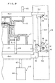
- the bracket 12 is fixed to the stationary member 50 by a bolt 14, the run-up lever 11 is rotatably provided around the center shaft 13, the run-up lever 11 can abut against an upper surface of the pressure-receiving portion 51, and the rollers 16, 18 are rotatably provided around the supporting shafts 17, 19 at the upper portions of the run-up lever 11 and the bracket 12, respectively.
- the operation cam 20' is disposed at position facing the rollers 16, 18, and is mounted to a supporting portion 52 through the supporting mount 21.
- the operation cam 20' is fixed to the supporting mount 21 by the bolt 23, and the supporting mount 21 is fixed to the supporting portion 52 by the bolt 24.
- the thin plate 24 is placed on the punch 2 and the blank holder 4.
- FIG. 6 shows a state in which the ram 42 is lowered and the run-up lever 11 starts abutting against the pressure-receiving portion 51 by the operation cam 20'.
- a run-up clearance H between the blank holder 4 and the die 6 shown in FIG. 6 is set to such a value that the blank holder 4 collides against the die 6 after run-up and a silent effect can sufficiently be obtained.
- the run-up lever 11 pushes the upper surface of the pressure-receiving portion 51 downward, thereby lowering the pad 44.
- the cushion pin 3 and the blank holder 4 are moved downward, the blank holder 4 is allowed to run up downward, and the die 6 abuts against the thin plate 24 on the blank holder 4.
- FIG. 7 shows this state.
- a clearance exists between the upper surface of the pad 44 and the lower surface of the bed 41, the cushion pin 3 is moved downward by the distance of this clearance, and the blank holder 4 is also moved downward.
- the die 6 abuts against the thin plate 24 on the running blank holder 4 not against the thin plate 24 on the stationary blank holder 4. Since the die 6 does not collide against the stationary thin plate 24 but collides against the running thin plate 24, little noise is generated.
- the upper die 5 is subsequently lowered and the drawing is completed at the bottom dead center shown in FIG. 8, thereby forming the work W.
- the work W When the upper die 5 moves upward, the work W is removed from the punch 2 by the blank holder 4.
- the die 6 is provided with an air vent 25 so that the negative pressure is prevented from being generated between the work W and the die 6 when the work W is dropped by its own weight.
- the work W may be moved out from the die 6 by a push-out pin (not shown) biased by a spring.
- the operation cam 20' becomes long, it is preferable to provide a guide, and the length thereof must be determined in accordance with the height of the pressing die. It is preferable to prepare some operation cams having different length or to prepare an operation cam which is extendable mechanically or by air pressure or hydraulically.
- the silent structure of the pressing machine has been described above, the silent structure can also be applied to a processing machine of metal or resin.
- a silent structure of a processing machine comprising a stationary bed, a movable a ram vertically movable with respect to the bed, a movable member vertically movable with respect to the bed, a pad of a cushion device located below the bed for biasing a cushion pin upward, wherein the stationary member is rotatably provided with a run-up lever, the movable member facing the run-up lever is vertically provided with an operation cam, the operation cam acts on the run-up lever before mounted working tools sandwich a work, and the pad is allowed to run up. Therefore, it is possible to reduce a noise generated by the processing machine as small as possible.
- a silent structure of a pressing machine comprising a stationary bed, a ram vertically movable with respect to the bed, a pad of a cushion device located below the bed for biasing a cushion pin upward, wherein the stationary member is rotatably provided with a run-up lever, the ram facing the run-up lever is vertically provided with an operation cam, the operation cam acts on the run-up lever before mounted pressing dies sandwich a thin plate or a work, and the pad is allowed to run up. Therefore, it is possible to reduce a noise generated by the pressing machine as small as possible.
- a silent structure of a drawing die comprising a punch, a blank holder fitted around the punch and vertically movably supported by a cushion pin, and a vertically movable die disposed such as to face the punch, a thin plate being placed on a blank holder which is moved up by the cushion pin, the die being lowered, thereby sandwiching the thin plate between the blank holder and the die for drawing the thin plate by the punch, wherein a lower die base plate is rotatably provided with a run-up lever for pushing the blank holder for allowing the latter to run up before the die collides against the thin plate, an operation cam for driving the run-up lever is disposed at a position on the die facing the run-up lever, and the die collides against the thin plate on the blank holder after the blank holder runs up.
- the present invention can be used as a silent structure for improving the existing drawing die if the run-up lever and the operation cam are formed as a unit.
- the run-up speed of the blank holder can be controlled by variously changing the tilt angles of the cam surface of the operation cam.
- the existing drawing die can easily be improved to include the silent structure.
- a silent structure of a pressing die comprising a lower die provided with an operation cam, and an upper die provided at its position facing the operation cam with a run-up lever, it can be expected that a noise of a noise source is reduced by the pad of the upper die.
- the thin plate or the work is allowed to run up before the thin plate or the work is sandwiched. Therefore, it can be expected that a noise of the pressing die is reduced.
Landscapes
- Engineering & Computer Science (AREA)
- Mechanical Engineering (AREA)
- Presses And Accessory Devices Thereof (AREA)
- Shaping Metal By Deep-Drawing, Or The Like (AREA)
Abstract
Description
Claims (7)
- A silent structure of a processing machine comprising a stationary bed, a movable member vertically movable with respect to said bed, a pad of a cushion device located below said bed for biasing a cushion pin upward, wherein said stationary member is rotatably provided with a run-up lever, said movable member facing said run-up lever is vertically provided with an operation cam, said operation cam acts on said run-up lever before mounted working tools sandwich a work, and said pad is allowed to run up.
- A silent structure of a pressing machine comprising a stationary bed, a ram vertically movable with respect to said bed, a pad of a cushion device located below said bed for biasing a cushion pin upward, wherein said stationary member is rotatably provided with a run-up lever, said ram facing said run-up lever is vertically provided with an operation cam, said operation cam acts on said run-up lever before mounted pressing dies sandwich a thin plate or a work, and said pad is allowed to run up.
- A silent structure of a drawing die comprising a punch, a blank holder fitted around said punch and vertically movably supported by a cushion pin, and a vertically movable die disposed such as to face said punch, a thin plate being placed on a blank holder which is moved up by said cushion pin, said die being lowered, thereby sandwiching said thin plate between said blank holder and said die for drawing said thin plate by said punch, wherein a lower die base plate is rotatably provided with a run-up lever for pushing said blank holder for allowing the latter to run up before said die collides against said thin plate, an operation cam for driving said run-up lever is disposed at a position on said die facing said run-up lever, and said die collides against said thin plate on said blank holder after said blank holder runs up.
- A silent structure of a drawing die according to said claim 3, wherein said operation cam has a cam surface a tilt angle for changing speed.
- A silent run-up unit having a run-up lever and an operation cam for driving said run-up lever.
- A silent structure of a pressing die comprising a lower die provided with an operation cam, and an upper die provided at its position facing said operation cam with a run-up lever.
- A pressing die for sandwiching a thin plate or a work to machine the same, wherein said thin plate or said work is allowed to run up before said thin plate or said work is sandwiched.
Applications Claiming Priority (2)
| Application Number | Priority Date | Filing Date | Title |
|---|---|---|---|
| JP06138999A JP3181888B2 (en) | 1999-03-09 | 1999-03-09 | Quiet structure of processing machine, quiet structure of press machine, silent type of drawing type and its silent run-up unit |
| JP6138999 | 1999-03-09 |
Publications (3)
| Publication Number | Publication Date |
|---|---|
| EP1034858A2 true EP1034858A2 (en) | 2000-09-13 |
| EP1034858A3 EP1034858A3 (en) | 2002-04-17 |
| EP1034858B1 EP1034858B1 (en) | 2004-07-28 |
Family
ID=13169774
Family Applications (1)
| Application Number | Title | Priority Date | Filing Date |
|---|---|---|---|
| EP99105848A Expired - Lifetime EP1034858B1 (en) | 1999-03-09 | 1999-03-23 | Processing machine including noise-reducing structure |
Country Status (7)
| Country | Link |
|---|---|
| US (1) | US6167741B1 (en) |
| EP (1) | EP1034858B1 (en) |
| JP (1) | JP3181888B2 (en) |
| KR (1) | KR20000062090A (en) |
| CA (1) | CA2268636C (en) |
| DE (1) | DE69918941T2 (en) |
| ES (1) | ES2226220T3 (en) |
Cited By (3)
| Publication number | Priority date | Publication date | Assignee | Title |
|---|---|---|---|---|
| WO2002096580A1 (en) * | 2001-05-31 | 2002-12-05 | Strömsholmen Ab | A method and a device for reducing the noise level at a deep-drawing press |
| WO2006038855A1 (en) * | 2004-10-01 | 2006-04-13 | Strömsholmen Ab | Striker plate and sheet-metal forming tool comprising such a striker plate |
| EP1657006A1 (en) * | 2004-11-16 | 2006-05-17 | Umix Co., Ltd. | Drawing die with stabilizer |
Families Citing this family (6)
| Publication number | Priority date | Publication date | Assignee | Title |
|---|---|---|---|---|
| US6418744B1 (en) | 2001-04-09 | 2002-07-16 | Earnest J. Neal | Method and apparatus for containing an ambient climate control system |
| DE102004030678B4 (en) * | 2004-06-24 | 2006-03-30 | Müller Weingarten AG | Cushioning device with hybrid drive |
| US7523634B2 (en) * | 2004-08-24 | 2009-04-28 | Helical Cam, Llc. | Forming die having filler cam assembly |
| JP4522378B2 (en) * | 2005-04-20 | 2010-08-11 | ジヤトコ株式会社 | Press molding method and apparatus |
| US8171821B2 (en) | 2006-09-28 | 2012-05-08 | Helical Cam, Llc | Corner cam assembly |
| US10486216B2 (en) | 2016-10-17 | 2019-11-26 | Ford Motor Company | Draw die and binder lock |
Family Cites Families (9)
| Publication number | Priority date | Publication date | Assignee | Title |
|---|---|---|---|---|
| US2843175A (en) * | 1955-02-24 | 1958-07-15 | Western Electric Co | Device with collapsible arbor for forming partially formed part into boxlike article |
| JPS5829530A (en) * | 1981-08-14 | 1983-02-21 | Nissan Motor Co Ltd | Press die for cushion drawing |
| EP0074421B1 (en) * | 1981-09-12 | 1985-05-22 | L. SCHULER GmbH | Deep-drawing arrangement for presses with mechanically driven drawing punch |
| JPS60176821U (en) * | 1984-04-27 | 1985-11-22 | 株式会社小松製作所 | dictation device |
| DE3623188C1 (en) * | 1986-07-10 | 1987-09-10 | Daimler Benz Ag | Working method for the deep-drawing of metal sheets, and a deep-drawing press which carries out this method |
| DE3640787A1 (en) * | 1986-11-28 | 1988-06-01 | Schuler Gmbh L | DRAWING DEVICE FOR A PRESS |
| CA2073204C (en) | 1992-07-06 | 1999-08-24 | Mitsuo Matsuoka | Noise reducing structure of slide-cam die |
| JP2928227B1 (en) | 1998-04-20 | 1999-08-03 | 株式会社 ジェーシーエム | Aperture type silent structure and its silent approach unit |
| CA2237509C (en) * | 1998-05-11 | 2006-06-27 | Umix Co., Ltd. | Structure for a drawing die and a run-up unit therefor |
-
1999
- 1999-03-09 JP JP06138999A patent/JP3181888B2/en not_active Expired - Fee Related
- 1999-03-23 DE DE69918941T patent/DE69918941T2/en not_active Expired - Fee Related
- 1999-03-23 EP EP99105848A patent/EP1034858B1/en not_active Expired - Lifetime
- 1999-03-23 ES ES99105848T patent/ES2226220T3/en not_active Expired - Lifetime
- 1999-04-09 CA CA002268636A patent/CA2268636C/en not_active Expired - Fee Related
- 1999-04-16 KR KR1019990013472A patent/KR20000062090A/en not_active Ceased
- 1999-04-28 US US09/300,316 patent/US6167741B1/en not_active Expired - Lifetime
Cited By (5)
| Publication number | Priority date | Publication date | Assignee | Title |
|---|---|---|---|---|
| WO2002096580A1 (en) * | 2001-05-31 | 2002-12-05 | Strömsholmen Ab | A method and a device for reducing the noise level at a deep-drawing press |
| US7124614B2 (en) | 2001-05-31 | 2006-10-24 | Stromsholmen Ab | Method and a device for reducing the noise level at a deep-drawing press |
| WO2006038855A1 (en) * | 2004-10-01 | 2006-04-13 | Strömsholmen Ab | Striker plate and sheet-metal forming tool comprising such a striker plate |
| US7818988B2 (en) | 2004-10-01 | 2010-10-26 | Stromsholmen Ab | Striker plate and sheet-metal forming tool comprising such a striker plate |
| EP1657006A1 (en) * | 2004-11-16 | 2006-05-17 | Umix Co., Ltd. | Drawing die with stabilizer |
Also Published As
| Publication number | Publication date |
|---|---|
| EP1034858A3 (en) | 2002-04-17 |
| JP3181888B2 (en) | 2001-07-03 |
| CA2268636A1 (en) | 2000-09-09 |
| KR20000062090A (en) | 2000-10-25 |
| DE69918941T2 (en) | 2005-09-29 |
| CA2268636C (en) | 2005-07-26 |
| DE69918941D1 (en) | 2004-09-02 |
| US6167741B1 (en) | 2001-01-02 |
| ES2226220T3 (en) | 2005-03-16 |
| JP2000254738A (en) | 2000-09-19 |
| EP1034858B1 (en) | 2004-07-28 |
Similar Documents
| Publication | Publication Date | Title |
|---|---|---|
| CA1241870A (en) | Hydro mechanical pressing method and punch and die therefor | |
| CA2268636C (en) | Noise-reducing structure of a processing machine | |
| EP0956913B1 (en) | Drawing die and press die with a noise reducing device | |
| JP2927171B2 (en) | Composite press mold | |
| JP3387207B2 (en) | Cam type for press | |
| JP3816319B2 (en) | Press mold structure | |
| KR101272544B1 (en) | UP and down device of press for up flange | |
| JP3407779B2 (en) | Press-type punching device | |
| JP2000233232A (en) | Press forming equipment for flange processing | |
| JPH06154865A (en) | Press die | |
| EP1657006B1 (en) | Drawing die with stabilizer | |
| JPH091258A (en) | Piercing method of soft material and soft laminated material with turret punch press machine | |
| CN220659012U (en) | Compressor upper cover punching machine | |
| JPH08132299A (en) | Press equipment | |
| KR100428346B1 (en) | An apparatus relieving impact for drawing mold | |
| CN213006695U (en) | Hydraulic rod assembly of punch press | |
| CN221109636U (en) | Punch head structure for stamping die | |
| CN222051316U (en) | Driving noise reduction mechanism of bending machine | |
| CN221414726U (en) | Wire harness support composite processing die and stamping equipment | |
| JPS5932419Y2 (en) | Press-type workpiece take-out device | |
| JP3412782B2 (en) | Punch press | |
| JPS6019776Y2 (en) | molding mold | |
| KR100476216B1 (en) | A retainer pin device for press | |
| JPH0718442Y2 (en) | Knockout device of press machine | |
| JP2523920Y2 (en) | Molding equipment for bulge molding |
Legal Events
| Date | Code | Title | Description |
|---|---|---|---|
| PUAI | Public reference made under article 153(3) epc to a published international application that has entered the european phase |
Free format text: ORIGINAL CODE: 0009012 |
|
| AK | Designated contracting states |
Kind code of ref document: A2 Designated state(s): AT BE CH CY DE DK ES FI FR GB GR IE IT LI LU MC NL PT SE Kind code of ref document: A2 Designated state(s): DE ES FR GB IT SE |
|
| AX | Request for extension of the european patent |
Free format text: AL;LT;LV;MK;RO;SI |
|
| PUAL | Search report despatched |
Free format text: ORIGINAL CODE: 0009013 |
|
| AK | Designated contracting states |
Kind code of ref document: A3 Designated state(s): AT BE CH CY DE DK ES FI FR GB GR IE IT LI LU MC NL PT SE |
|
| AX | Request for extension of the european patent |
Free format text: AL;LT;LV;MK;RO;SI |
|
| RIC1 | Information provided on ipc code assigned before grant |
Free format text: 7B 21D 22/22 A, 7B 21D 24/12 B, 7B 21D 24/04 B |
|
| 17P | Request for examination filed |
Effective date: 20021015 |
|
| AKX | Designation fees paid |
Free format text: DE ES FR GB IT SE |
|
| 17Q | First examination report despatched |
Effective date: 20030530 |
|
| GRAP | Despatch of communication of intention to grant a patent |
Free format text: ORIGINAL CODE: EPIDOSNIGR1 |
|
| RTI1 | Title (correction) |
Free format text: PROCESSING MACHINE INCLUDING NOISE-REDUCING STRUCTURE |
|
| GRAS | Grant fee paid |
Free format text: ORIGINAL CODE: EPIDOSNIGR3 |
|
| GRAA | (expected) grant |
Free format text: ORIGINAL CODE: 0009210 |
|
| AK | Designated contracting states |
Kind code of ref document: B1 Designated state(s): DE ES FR GB IT SE |
|
| REG | Reference to a national code |
Ref country code: GB Ref legal event code: FG4D |
|
| REG | Reference to a national code |
Ref country code: SE Ref legal event code: TRGR |
|
| REG | Reference to a national code |
Ref country code: IE Ref legal event code: FG4D |
|
| REF | Corresponds to: |
Ref document number: 69918941 Country of ref document: DE Date of ref document: 20040902 Kind code of ref document: P |
|
| REG | Reference to a national code |
Ref country code: ES Ref legal event code: FG2A Ref document number: 2226220 Country of ref document: ES Kind code of ref document: T3 |
|
| ET | Fr: translation filed | ||
| PLBE | No opposition filed within time limit |
Free format text: ORIGINAL CODE: 0009261 |
|
| STAA | Information on the status of an ep patent application or granted ep patent |
Free format text: STATUS: NO OPPOSITION FILED WITHIN TIME LIMIT |
|
| 26N | No opposition filed |
Effective date: 20050429 |
|
| PGFP | Annual fee paid to national office [announced via postgrant information from national office to epo] |
Ref country code: ES Payment date: 20060320 Year of fee payment: 8 |
|
| PGFP | Annual fee paid to national office [announced via postgrant information from national office to epo] |
Ref country code: FR Payment date: 20060322 Year of fee payment: 8 |
|
| PGFP | Annual fee paid to national office [announced via postgrant information from national office to epo] |
Ref country code: IT Payment date: 20060331 Year of fee payment: 8 |
|
| PG25 | Lapsed in a contracting state [announced via postgrant information from national office to epo] |
Ref country code: SE Free format text: LAPSE BECAUSE OF NON-PAYMENT OF DUE FEES Effective date: 20070324 |
|
| EUG | Se: european patent has lapsed | ||
| GBPC | Gb: european patent ceased through non-payment of renewal fee |
Effective date: 20070323 |
|
| REG | Reference to a national code |
Ref country code: FR Ref legal event code: ST Effective date: 20071130 |
|
| PGFP | Annual fee paid to national office [announced via postgrant information from national office to epo] |
Ref country code: SE Payment date: 20060324 Year of fee payment: 8 |
|
| PG25 | Lapsed in a contracting state [announced via postgrant information from national office to epo] |
Ref country code: GB Free format text: LAPSE BECAUSE OF NON-PAYMENT OF DUE FEES Effective date: 20070323 |
|
| REG | Reference to a national code |
Ref country code: ES Ref legal event code: FD2A Effective date: 20070324 |
|
| PG25 | Lapsed in a contracting state [announced via postgrant information from national office to epo] |
Ref country code: FR Free format text: LAPSE BECAUSE OF NON-PAYMENT OF DUE FEES Effective date: 20070402 Ref country code: ES Free format text: LAPSE BECAUSE OF NON-PAYMENT OF DUE FEES Effective date: 20070324 |
|
| PGFP | Annual fee paid to national office [announced via postgrant information from national office to epo] |
Ref country code: DE Payment date: 20080529 Year of fee payment: 10 |
|
| PGFP | Annual fee paid to national office [announced via postgrant information from national office to epo] |
Ref country code: GB Payment date: 20060323 Year of fee payment: 8 |
|
| PG25 | Lapsed in a contracting state [announced via postgrant information from national office to epo] |
Ref country code: IT Free format text: LAPSE BECAUSE OF NON-PAYMENT OF DUE FEES Effective date: 20070323 |
|
| PG25 | Lapsed in a contracting state [announced via postgrant information from national office to epo] |
Ref country code: DE Free format text: LAPSE BECAUSE OF NON-PAYMENT OF DUE FEES Effective date: 20091001 |