EP1390108B1 - A skate, particularly for aggressive skating - Google Patents
A skate, particularly for aggressive skating Download PDFInfo
- Publication number
- EP1390108B1 EP1390108B1 EP02754602A EP02754602A EP1390108B1 EP 1390108 B1 EP1390108 B1 EP 1390108B1 EP 02754602 A EP02754602 A EP 02754602A EP 02754602 A EP02754602 A EP 02754602A EP 1390108 B1 EP1390108 B1 EP 1390108B1
- Authority
- EP
- European Patent Office
- Prior art keywords
- sole
- sports shoe
- skate
- skate according
- screws
- Prior art date
- Legal status (The legal status is an assumption and is not a legal conclusion. Google has not performed a legal analysis and makes no representation as to the accuracy of the status listed.)
- Expired - Lifetime
Links
Images

Classifications
-
- A—HUMAN NECESSITIES
- A63—SPORTS; GAMES; AMUSEMENTS
- A63C—SKATES; SKIS; ROLLER SKATES; DESIGN OR LAYOUT OF COURTS, RINKS OR THE LIKE
- A63C17/00—Roller skates; Skate-boards
- A63C17/04—Roller skates; Skate-boards with wheels arranged otherwise than in two pairs
- A63C17/06—Roller skates; Skate-boards with wheels arranged otherwise than in two pairs single-track type
-
- A—HUMAN NECESSITIES
- A43—FOOTWEAR
- A43B—CHARACTERISTIC FEATURES OF FOOTWEAR; PARTS OF FOOTWEAR
- A43B5/00—Footwear for sporting purposes
- A43B5/005—Footwear for sporting purposes for grinding, i.e. sliding on the sole or a part thereof
-
- A—HUMAN NECESSITIES
- A43—FOOTWEAR
- A43B—CHARACTERISTIC FEATURES OF FOOTWEAR; PARTS OF FOOTWEAR
- A43B5/00—Footwear for sporting purposes
- A43B5/16—Skating boots
- A43B5/1641—Skating boots characterised by the sole ; characterised by the attachment of the skate
-
- A—HUMAN NECESSITIES
- A63—SPORTS; GAMES; AMUSEMENTS
- A63C—SKATES; SKIS; ROLLER SKATES; DESIGN OR LAYOUT OF COURTS, RINKS OR THE LIKE
- A63C2201/00—Use of skates, skis, roller-skates, snowboards and courts
- A63C2201/02—Aggressive riding, e.g. grinding
Definitions
- the present invention relates to an improved skate, which is particularly suitable for the practice of so-called "aggressive" skating.
- skates used for this sports practice, comprise a frame which supports a plurality of in-line wheels and a sports shoe associated to the frame.
- the sports shoe comprises a rigid sole and a shell, which is usually connected to a cuff.
- the shell and the cuff surround an internal liner for accommodating the user's foot.
- the shell and the cuff are fitted with a pair of opposing flaps that may be fastened together through suitable fastening buckles arranged transversely to these flaps.
- a first shortcoming consists in that the walls of the shell and/or cuff are relatively thick, since their function is to ensure a satisfactory transmission of forces to the frame and, overall, ensure protection for the foot and the lower portion of the user's leg. This fact entails that the skate is often cumbersome, heavy and unattractive from the aesthetic point of view. This problem is worsened by the fact that the acrobatic sport activity causes damages to the outer surface of the skate, which thus shortly appears somewhat scratched and ruined. A further problem consists in that the plastic shell and/or cuff do not allow a satisfactory transpiration of the user's foot. This fact, combined with the relatively high sturdiness of the shell, implies that known skates are often uncomfortable and present high levels of internal moisture and temperature. Document WO 99/43400 discloses a skate according to the preamble of claim 1.
- the aim of the present invention is to provide a skate, particularly suitable for "aggressive" sports practice, which ensures a suitable protection for the foot and the lower portion of the user's leg against impacts and other accidental events and which ensures, at the same time, a relatively high level of comfort for the user and a pleasing aesthetic appearance.
- an object of the present invention is to provide a skate which has reduced weight and overall size.
- Another object of the present invention is to provide a skate which is structurally simple and has low manufacturing costs.
- a skate which comprises:
- the skate according to the present invention, will be described hereinafter with particular reference to its use in "aggressive" skating. This is only for sake of simplicity and it does not imply any limitation of the scope of the present invention. In fact, the present gliding device can be advantageously used without distinction in many other gliding sports such as traditional or speed skating, rolling and the like.
- the skate 1 comprises a frame 2 supporting a plurality of wheels 3.
- the frame 2 is connected, at the top, to a rigid sole 4, through the insertion of a toe plate 5a and a heel plate 5b.
- the sole 4 is in turn connected to the sports shoe 6.
- the sole 4 is arranged so as to wrap around a lower portion 61 of the sports shoe 2.
- the plates 5a and 5b are preferably made of a shockproof and wearproof material. It should be noticed that the presence of the plates 5a and 5b, by co-operating with sole 4, allows making the structure of the skate 1 particularly sturdy and resistant to impacts or other accidental events.
- the interconnection between the frame 2 and the sports shoe 6 is preferably accomplished by means of first screws (not illustrated), which are arranged with the head towards the ground and the shank towards the sports shoe 6.
- first screws pass advantageously through a pair of first holes 7a and 7b, made in the frame 2.
- first screws are arranged to pass through second holes 8a and 8b, through an advantageously rectangular opening 9a and a third hole 9b.
- the second holes 8a and 8b are provided on the respective toe plate 5a and heel plate 5b while the opening 9a and the third hole 9b are made at the bottom of the sole 4.
- the first screws are advantageously connected to counter-threaded first dead holes (not illustrated), which are provided at the bottom portion 61 of the sports shoe 6. According to the needs, such first dead holes may advantageously house counter-threaded bushes (not shown).
- the interconnection between the plates 5a and 5b, the sole 4 and the sports shoe 6 is also guaranteed by second screws (not shown), which are arranged to pass through the plates 5a and 5b and the sole 4.
- Such second screws are advantageously connected with counter-threaded second dead holes, which are provided at the bottom portion 61 of the sports shoe 6, approximately around said first dead holes.
- the plates 5a and 5b comprise advantageously a plurality of dowel pins 10, which are axially perforated to allow the passage of the second screws.
- the dowel pins 10 project from the top of the plates 5a and 5b, towards the sports shoe 6.
- the dowel pins 10 may be positioned in counter-shaped fourth holes 11 made in the sole 4. In this manner, a more precise and stable interconnection of the plates 5a and 5b to the sports shoe 6 is achieved.
- the sports shoe 6 comprises a soft upper 12, which is suitably connected at the bottom to the sole 4.
- the upper 12 is fitted with a first pair of flaps 13a and 13b on which a succession of eyelets 14 are advantageously provided to allow the passage of a fastening lace 15.
- the soft upper 12 is advantageously made of soft materials, such as fabric, leather or similar materials.
- the soft upper may be arranged to surround the bottom portion 61 of the sports shoe 6. In this case, it is provided with a plurality of fifth holes (not shown), which are suitable for allow the passage of said first screws and second screws (or the dowel pins 10).
- the sports shoe 6 comprises a rigid or semi-rigid shell 16, which is advantageously open on the upper surface of the foot.
- the shell 16 is removably connected internally to the soft upper 12.
- the sports shoe comprises advantageously a cuff 17, suitable for supporting the lower leg of the user, in particular the calf region.
- the cuff 17 is mounted on the shell 16.
- the shell 16 is made of rigid or semi-rigid material, such as plastics, thereby permitting an excellent transmission of the forces to the frame 2 by the user.
- it can be adopted for fixing on a solid base said first screws and second screws.
- the mentioned first dead holes and second dead holes can be provided at the bottom of the shell 16.
- An internal liner 18 is removably associated to the shell 16 and the cuff 17 for accommodating the user's foot, thereby guaranteeing an excellent comfort.
- the liner 18 and the cuff 17 are preferably fitted respectively with a second pair of opposing flaps 19a and 19b and with a third pair of opposing flaps 20a and 20b.
- the second pair and the third pair of flaps are closable over each other once the skate 1 has been put on.
- at least one fastening buckle 21 is arranged transversely to the cuff 17.
- the soft upper 12 is preferably arranged to fully wrap around both the shell 16 and the cuff 17. In this manner, the soft upper 12 provides the skate 1 with an appealing appearance, which is equivalent to that offered by lightweight, traditional types of speeding skates.
- the soft upper 12 is provided with a pair of strap ends 22a and 22b, which project at the front of the sports shoe 6 from opposite sides, approximately close to the ends of the fastening buckle 21.
- the strap ends 22a and 22b are advantageously designed to fit over the buckle 21.
- they comprise interconnection means 25, which allow them to be temporarily joined together, thereby forming a covering and protective element for the fastening buckle 21, against wear, impacts and/or accidental openings.
- one or more rigid strips 23 are connected laterally to the soft upper 12.
- the strips 23 are suitably made of materials resistant to rubbing and provided with adequate thickness to project from the upper 12, thereby acting as a protection for the same.
- the shell 16 and the cuff 17 may be suitably designed for ensuring a good transmission of forces only and not for having necessarily protection purposes. Therefore, the thickness of the walls of the shell 16 and the cuff 17 can be remarkably reduced and provided with suitable opening to allow a good transpiration of the user's foot, with consequent increase of comfort for the user.
- the shell 16 and the cuff 17 may even be reduced to an essential frame structure, provided with few supporting elements and having the sole purpose of transmitting forces to the frame 2.
- the user can put on the skate 1, according to the present invention, very easily.
- the user by opening the straps 22a and 22b and the fastening buckle 21, may pull apart the second pair of flaps 19a, 19b and the third pair of flaps 20a and 20b, thus being able to introduce the foot into the sports shoe 6.
- the sports shoe 6 may subsequently be closed by means of the fastening buckle 21, acting near the instep, and also by means of the lace 15, passing through the eyelets 14 of the first pair of flaps 13a and 13b.
- the protection of the fastening buckle 21 may be guaranteed by positioning the strap ends 22a and 22b over it and fastening them together by way of the interconnection means 25.
- skate 1 achieves the above aim and objects.
- the skate 1 is provided with a particularly sturdy structure, which makes it particularly suitable for aggressive skating. Nevertheless, the soft upper 12 provides the skate 1 with a pleasant appearance and it allows arranging the shell and/or cuff in order to permit a suitable transpiration level of the user's foot. Morever, the presence of the liner 18 improves the comfort for the user.
- sport practice particularly aggressive skating, can be accomplished with maximum effectiveness and in total safety and comfort for the user, with a skate 1, which is provided also with a relevant aestethic impact.
- the structural simplicity of the skate 1, according to the present invention allows it to be manufactured at relatively low time and costs.
Abstract
Description
- The present invention relates to an improved skate, which is particularly suitable for the practice of so-called "aggressive" skating.
- Nowadays, "aggressive" skating is quite known and widespread. Basically, this kind of sports practice consists of a series of acrobatics movements such as, for example, the so-called "grinding" (i.e. a crosswise passage along kerbs or handrails) or other stunt movements. Known skates, used for this sports practice, comprise a frame which supports a plurality of in-line wheels and a sports shoe associated to the frame. The sports shoe comprises a rigid sole and a shell, which is usually connected to a cuff. The shell and the cuff surround an internal liner for accommodating the user's foot. The shell and the cuff are fitted with a pair of opposing flaps that may be fastened together through suitable fastening buckles arranged transversely to these flaps.
- However, the skates of the known type suffer some drawbacks.
- A first shortcoming consists in that the walls of the shell and/or cuff are relatively thick, since their function is to ensure a satisfactory transmission of forces to the frame and, overall, ensure protection for the foot and the lower portion of the user's leg. This fact entails that the skate is often cumbersome, heavy and unattractive from the aesthetic point of view. This problem is worsened by the fact that the acrobatic sport activity causes damages to the outer surface of the skate, which thus shortly appears somewhat scratched and ruined. A further problem consists in that the plastic shell and/or cuff do not allow a satisfactory transpiration of the user's foot. This fact, combined with the relatively high sturdiness of the shell, implies that known skates are often uncomfortable and present high levels of internal moisture and temperature. Document
WO 99/43400 - Therefore, the aim of the present invention is to provide a skate, particularly suitable for "aggressive" sports practice, which ensures a suitable protection for the foot and the lower portion of the user's leg against impacts and other accidental events and which ensures, at the same time, a relatively high level of comfort for the user and a pleasing aesthetic appearance.
- Within this aim, an object of the present invention is to provide a skate which has reduced weight and overall size.
- Another object of the present invention is to provide a skate which is structurally simple and has low manufacturing costs.
- Therefore, the present invention provides a skate, which comprises:
- a frame supporting a plurality of wheels; and
- a sports shoe comprising a rigid sole, which is connected to the frame and a soft upper, which is downwardly connected to the sole, the sports shoe comprising a shell, which is removably associated to the sole and an internal liner, which is removably associated to the shell, the liner being aimed at accommodating the foot and/or the lower portion of the user's leg, characterised in that it comprises a toe plate and a heel plate, which are inserted between the frame and the rigid sole and are separated between them, the toe plate and the heel plate being arranged so as to co-operate with the sole for improving the sturdiness of the structure of the skate.
- Further characteristics and advantages of the skate, according to the present invention, will become better apparent from the following detailed description of some particular embodiments thereof, illustrated by way of non-limitative example in the accompanying drawings, wherein:
-
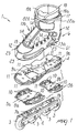
Figure 1 is an exploded perspective view of the skate, according to the present invention; -
Figure 2 is an exploded perspective view of a detail of the skate, according to the present invention. - The skate, according to the present invention, will be described hereinafter with particular reference to its use in "aggressive" skating. This is only for sake of simplicity and it does not imply any limitation of the scope of the present invention. In fact, the present gliding device can be advantageously used without distinction in many other gliding sports such as traditional or speed skating, rolling and the like.
- With reference to the figures, the skate 1, according to the present invention, comprises a
frame 2 supporting a plurality ofwheels 3. Theframe 2 is connected, at the top, to arigid sole 4, through the insertion of atoe plate 5a and aheel plate 5b. The sole 4 is in turn connected to thesports shoe 6. Preferably, the sole 4 is arranged so as to wrap around alower portion 61 of thesports shoe 2. Theplates plates - According to a preferred embodiment of the present invention shown in
Figure 1 , the interconnection between theframe 2 and thesports shoe 6 is preferably accomplished by means of first screws (not illustrated), which are arranged with the head towards the ground and the shank towards thesports shoe 6. Such first screws pass advantageously through a pair of first holes 7a and 7b, made in theframe 2. Moreover, such first screws are arranged to pass throughsecond holes second holes respective toe plate 5a andheel plate 5b while the opening 9a and the third hole 9b are made at the bottom of the sole 4. The first screws are advantageously connected to counter-threaded first dead holes (not illustrated), which are provided at thebottom portion 61 of thesports shoe 6. According to the needs, such first dead holes may advantageously house counter-threaded bushes (not shown). The interconnection between theplates sports shoe 6 is also guaranteed by second screws (not shown), which are arranged to pass through theplates bottom portion 61 of thesports shoe 6, approximately around said first dead holes. - The
plates dowel pins 10, which are axially perforated to allow the passage of the second screws. Thedowel pins 10 project from the top of theplates sports shoe 6. Thedowel pins 10 may be positioned in counter-shapedfourth holes 11 made in the sole 4. In this manner, a more precise and stable interconnection of theplates sports shoe 6 is achieved. - The
sports shoe 6 comprises a soft upper 12, which is suitably connected at the bottom to the sole 4. The upper 12 is fitted with a first pair offlaps 13a and 13b on which a succession ofeyelets 14 are advantageously provided to allow the passage of afastening lace 15. The soft upper 12 is advantageously made of soft materials, such as fabric, leather or similar materials. The soft upper may be arranged to surround thebottom portion 61 of thesports shoe 6. In this case, it is provided with a plurality of fifth holes (not shown), which are suitable for allow the passage of said first screws and second screws (or the dowel pins 10). - The
sports shoe 6 comprises a rigid orsemi-rigid shell 16, which is advantageously open on the upper surface of the foot. Preferably, theshell 16 is removably connected internally to the soft upper 12. The sports shoe comprises advantageously acuff 17, suitable for supporting the lower leg of the user, in particular the calf region. Thecuff 17 is mounted on theshell 16. Theshell 16 is made of rigid or semi-rigid material, such as plastics, thereby permitting an excellent transmission of the forces to theframe 2 by the user. Thus, it can be adopted for fixing on a solid base said first screws and second screws. For this aim, the mentioned first dead holes and second dead holes can be provided at the bottom of theshell 16. - An
internal liner 18 is removably associated to theshell 16 and thecuff 17 for accommodating the user's foot, thereby guaranteeing an excellent comfort. Theliner 18 and thecuff 17 are preferably fitted respectively with a second pair of opposingflaps 19a and 19b and with a third pair of opposing flaps 20a and 20b. The second pair and the third pair of flaps are closable over each other once the skate 1 has been put on. To ensure excellent closure, at least one fastening buckle 21 is arranged transversely to thecuff 17. The soft upper 12 is preferably arranged to fully wrap around both theshell 16 and thecuff 17. In this manner, the soft upper 12 provides the skate 1 with an appealing appearance, which is equivalent to that offered by lightweight, traditional types of speeding skates. - Advantageously, the soft upper 12 is provided with a pair of strap ends 22a and 22b, which project at the front of the
sports shoe 6 from opposite sides, approximately close to the ends of the fastening buckle 21. The strap ends 22a and 22b are advantageously designed to fit over the buckle 21. Advantageously, they comprise interconnection means 25, which allow them to be temporarily joined together, thereby forming a covering and protective element for the fastening buckle 21, against wear, impacts and/or accidental openings. - To provide the upper 12 with an adequate protection against impact, friction or rubbing, one or more
rigid strips 23 are connected laterally to the soft upper 12. Thestrips 23 are suitably made of materials resistant to rubbing and provided with adequate thickness to project from the upper 12, thereby acting as a protection for the same. This means that theshell 16 and thecuff 17 may be suitably designed for ensuring a good transmission of forces only and not for having necessarily protection purposes. Therefore, the thickness of the walls of theshell 16 and thecuff 17 can be remarkably reduced and provided with suitable opening to allow a good transpiration of the user's foot, with consequent increase of comfort for the user. Thus, theshell 16 and thecuff 17 may even be reduced to an essential frame structure, provided with few supporting elements and having the sole purpose of transmitting forces to theframe 2. - The user can put on the skate 1, according to the present invention, very easily.
- Operation is as follows: the user, by opening the
straps 22a and 22b and the fastening buckle 21, may pull apart the second pair offlaps 19a, 19b and the third pair of flaps 20a and 20b, thus being able to introduce the foot into thesports shoe 6. Thesports shoe 6 may subsequently be closed by means of the fastening buckle 21, acting near the instep, and also by means of thelace 15, passing through theeyelets 14 of the first pair offlaps 13a and 13b. The protection of the fastening buckle 21 may be guaranteed by positioning the strap ends 22a and 22b over it and fastening them together by way of the interconnection means 25. - It has thus been shown that the skate 1, according to the present invention, achieves the above aim and objects.
- In fact, the skate 1 is provided with a particularly sturdy structure, which makes it particularly suitable for aggressive skating. Nevertheless, the soft upper 12 provides the skate 1 with a pleasant appearance and it allows arranging the shell and/or cuff in order to permit a suitable transpiration level of the user's foot. Morever, the presence of the
liner 18 improves the comfort for the user. Thus, sport practice, particularly aggressive skating, can be accomplished with maximum effectiveness and in total safety and comfort for the user, with a skate 1, which is provided also with a relevant aestethic impact. - Finally, the structural simplicity of the skate 1, according to the present invention, allows it to be manufactured at relatively low time and costs.
Claims (12)
- A skate (1) comprising:a frame (2) supporting a plurality of wheels (3);a sports shoe (6) comprising a rigid sole (4), which is connected to said frame, and a soft upper (12), which is downwardly connected to said sole, said sports shoe further comprising a shell (16), which is removably associated to said sole (4), said sports shoe further comprising an internal liner (18), which is removably associated to said shell (16), said liner accommodating the foot and/or the lower leg of the user;characterised in that it comprises a toe plate (5a) and a heel plate (5b), which are inserted between said frame and said rigid sole and are separated between them, said toe plate (5a) and said heel plate (5b) being arranged so as to co-operate with said sole for improving the sturdiness of said skate.
- The skate according to claim 1, characterised in that a cuff (17) is pivotally connected to said rigid shell (16).
- The skate according to claim 1, characterised in that said sole (4) is arranged so as to wrap around at least a bottom portion (61) of said sports shoe.
- The skate according to one or more of the preceding claims,
characterised in that said frame and said sports shoe are connected by means of first screws, which are positioned with the head towards the ground and the shank towards the sports shoe, said first screws passing through first holes (7a, 7b) obtained on said frame (2). - The skate according to claim 4, characterised in that said first screws pass through second holes (8a,8b), which are obtained on said toe plate and/or said heel plate, said first screws passing also through at least a front opening (9a) and a third hole (9b), which are provided on said sole, said first screws being connectable to counter-threaded first dead holes, which are provided at the bottom portion of said sports shoe.
- The skate according to one or more of the preceding claims,
characterised in that said sole, said toe plate, said heel plate and said bottom portion of said sports shoe are connected by means of second screws which pass through said toe plate and/or said heel plate and/or said sole, said second screws being connectable to counter-threaded second dead holes which are provided at the bottom portion (61) of said sports shoe, approximately around said first dead holes. - The skate according to claim 6, characterised in that said first plate and said second plate comprise a plurality of axially perforated dowel pins (10), which project upwardly of said toe plate and said heel plate, said dowel pins passing through counter-shaped fourth holes (11) which are provided on said sole, said second screws passing through said dowel pins (10).
- The skate according to one or more of the preceding claims,
characterised in that said soft upper (12) comprises a first pair of flaps (13a,13b), on which a plurality of eyelets (14) are advantageously arranged, said eyelets being suitable for the passage of a fastening lace (15). - The skate according to one or more of the preceding claims,
characterised in that said cuff (17) and said liner (18) comprise respectively a second pair of flaps and a third pair of flaps, said second pair of flaps (19a,19b) and said third pair of flaps (20a,20b) being arranged, so as to be closable over each other by means of at least a fastening buckle (21), which is arranged transversely to said second pair of flaps. - The skate according to claim 9, characterised in that said soft upper (12) comprises at least a protection strap end (22a;22b) which is positioned over said fastening buckle (21) for protecting said fastening buckle from wear, impacts and/or accidental openings.
- The skate according to one or more of the preceding claims,
characterised in that said upper (12) is arranged so as to wrap around said shell (16) and said cuff (17). - The skate according to one or more of the preceding claims,
characterised in that said upper (12) comprises at least a protection strip (23) which projects from said upper, so as to protect said upper from wear, impacts and other accidental events.
Applications Claiming Priority (3)
| Application Number | Priority Date | Filing Date | Title |
|---|---|---|---|
| ITTV20010070 | 2001-05-31 | ||
| IT2001TV000070A ITTV20010070A1 (en) | 2001-05-31 | 2001-05-31 | STRUCTURE OF SHOE |
| PCT/EP2002/005928 WO2002102478A2 (en) | 2001-05-31 | 2002-05-29 | A skate, particularly for aggressive skating |
Publications (2)
| Publication Number | Publication Date |
|---|---|
| EP1390108A2 EP1390108A2 (en) | 2004-02-25 |
| EP1390108B1 true EP1390108B1 (en) | 2009-04-08 |
Family
ID=11460077
Family Applications (1)
| Application Number | Title | Priority Date | Filing Date |
|---|---|---|---|
| EP02754602A Expired - Lifetime EP1390108B1 (en) | 2001-05-31 | 2002-05-29 | A skate, particularly for aggressive skating |
Country Status (7)
| Country | Link |
|---|---|
| US (1) | US20050248106A1 (en) |
| EP (1) | EP1390108B1 (en) |
| AT (1) | ATE427779T1 (en) |
| AU (1) | AU2002321049A1 (en) |
| DE (1) | DE60231871D1 (en) |
| IT (1) | ITTV20010070A1 (en) |
| WO (1) | WO2002102478A2 (en) |
Families Citing this family (5)
| Publication number | Priority date | Publication date | Assignee | Title |
|---|---|---|---|---|
| WO2007038493A2 (en) * | 2005-09-26 | 2007-04-05 | Kevin Raser | In-line skates, frame assemblies and assemblies for modifying in-line skates |
| US7594666B2 (en) * | 2006-06-13 | 2009-09-29 | Sunshine Distribution, Inc. | Skate assembly |
| US20080246235A1 (en) * | 2007-04-05 | 2008-10-09 | Joshua Alexander | Shock absorbing tandem roller skate |
| US20110316243A1 (en) * | 2010-06-23 | 2011-12-29 | Nistevo Sport Manufacturing Corporation | Skate assembly with external mounting blocks |
| US11071347B2 (en) | 2018-05-31 | 2021-07-27 | S-Ride, LLC | Suspension membranes, footwear including the same, footwear components, and related methods |
Family Cites Families (14)
| Publication number | Priority date | Publication date | Assignee | Title |
|---|---|---|---|---|
| US5234230A (en) * | 1992-12-10 | 1993-08-10 | Crane Scott A | Ankle and foot protective device for attachment to a skate |
| US5873584A (en) * | 1995-01-17 | 1999-02-23 | Rike Inline, Inc. | In-line roller skate frame |
| IT1279444B1 (en) * | 1995-09-22 | 1997-12-10 | Nordica Spa | SHOE STRUCTURE IN PARTICULAR FOR SKATES |
| FR2755585B1 (en) * | 1996-11-08 | 1999-01-29 | Salomon Sa | SPORT SHOE WITH MOBILE COLLAR |
| FR2755586B1 (en) * | 1996-11-08 | 1999-01-29 | Salomon Sa | METHOD FOR ASSEMBLING A SHOE TO A SPORTS ARTICLE CHASSIS |
| CA2227325A1 (en) * | 1997-01-17 | 1998-07-17 | Dirk L. Cornelius | Grind plate for skates |
| FR2759552B1 (en) * | 1997-02-19 | 1999-04-23 | Salomon Sa | SPORT SHOE WITH RIGID FRAME |
| US6164669A (en) * | 1997-06-20 | 2000-12-26 | K-2 Corporation | In-line skate base with replaceable wear pads |
| US6102412A (en) * | 1998-02-03 | 2000-08-15 | Rollerblade, Inc. | Skate with a molded boot |
| CA2287829A1 (en) * | 1998-02-27 | 1999-09-02 | Bertrand Racine | In-line roller skate with slotted boot/frame interface |
| US6045144A (en) * | 1998-12-19 | 2000-04-04 | Wong; Jack | Adjustable roller skate |
| FR2801771B1 (en) * | 1999-12-01 | 2003-02-07 | Salomon Sa | SPORTS SHOE WITH VARIABLE RIGIDITY |
| FR2804878B1 (en) * | 2000-02-11 | 2002-07-05 | Salomon Sa | SPORTS CHASSIS |
| JP2001314542A (en) * | 2000-05-02 | 2001-11-13 | Shunsei Cho | Structure of roller sneakers |
-
2001
- 2001-05-31 IT IT2001TV000070A patent/ITTV20010070A1/en unknown
-
2002
- 2002-05-29 DE DE60231871T patent/DE60231871D1/en not_active Expired - Lifetime
- 2002-05-29 WO PCT/EP2002/005928 patent/WO2002102478A2/en not_active Application Discontinuation
- 2002-05-29 AT AT02754602T patent/ATE427779T1/en not_active IP Right Cessation
- 2002-05-29 US US10/333,476 patent/US20050248106A1/en not_active Abandoned
- 2002-05-29 EP EP02754602A patent/EP1390108B1/en not_active Expired - Lifetime
- 2002-05-29 AU AU2002321049A patent/AU2002321049A1/en not_active Abandoned
Also Published As
| Publication number | Publication date |
|---|---|
| WO2002102478A2 (en) | 2002-12-27 |
| AU2002321049A1 (en) | 2003-01-02 |
| ATE427779T1 (en) | 2009-04-15 |
| EP1390108A2 (en) | 2004-02-25 |
| DE60231871D1 (en) | 2009-05-20 |
| US20050248106A1 (en) | 2005-11-10 |
| ITTV20010070A0 (en) | 2001-05-31 |
| WO2002102478A3 (en) | 2003-03-20 |
| ITTV20010070A1 (en) | 2002-12-01 |
Similar Documents
| Publication | Publication Date | Title |
|---|---|---|
| US4445287A (en) | Skate boot cover | |
| US8578633B2 (en) | Article of footwear with improved stability and balance | |
| US6082027A (en) | Size-adjustable footwear | |
| US5564203A (en) | Instep lacing component system | |
| CA1336230C (en) | Sport shoe | |
| US20010015023A1 (en) | Footwear | |
| US9266007B2 (en) | Goalie skate | |
| CA2205884C (en) | Sports shoe | |
| US5408763A (en) | Skate with aligned wheels having an adjustable quarter | |
| US6371494B1 (en) | Sports boot with variable rigidity | |
| US20150189942A1 (en) | Footwear With Two Tongues | |
| US6460274B1 (en) | Footwear part of a boot or equipment involving a footwear component | |
| US4376344A (en) | Insulated boot blanket | |
| EP1390108B1 (en) | A skate, particularly for aggressive skating | |
| EP1020210B1 (en) | Support device, particularly for shoes | |
| EP1362521A1 (en) | Improved sports shoe | |
| EP1299015B1 (en) | A sports shoe for a gliding sport | |
| EP0465223A2 (en) | Improved activity boot | |
| EP1389925B1 (en) | A gliding device | |
| CA2238844A1 (en) | Improved skate boot | |
| CA1046271A (en) | Fast closing athletic boot | |
| CA2224897C (en) | Skate boot having a molded outsole with raised regions | |
| WO2001067906A1 (en) | Sports shoe for children | |
| GB2347610A (en) | Footwear with inflated bladder | |
| WO2005046813A1 (en) | Outline skate |
Legal Events
| Date | Code | Title | Description |
|---|---|---|---|
| PUAI | Public reference made under article 153(3) epc to a published international application that has entered the european phase |
Free format text: ORIGINAL CODE: 0009012 |
|
| 17P | Request for examination filed |
Effective date: 20030120 |
|
| AK | Designated contracting states |
Kind code of ref document: A2 Designated state(s): AT BE CH CY DE DK ES FI FR GB GR IE IT LI LU MC NL PT SE TR |
|
| AX | Request for extension of the european patent |
Extension state: AL LT LV MK RO SI |
|
| RAP1 | Party data changed (applicant data changed or rights of an application transferred) |
Owner name: ROLLERBLADE SRL |
|
| RAP1 | Party data changed (applicant data changed or rights of an application transferred) |
Owner name: NORDICA S.P.A |
|
| GRAP | Despatch of communication of intention to grant a patent |
Free format text: ORIGINAL CODE: EPIDOSNIGR1 |
|
| GRAS | Grant fee paid |
Free format text: ORIGINAL CODE: EPIDOSNIGR3 |
|
| GRAA | (expected) grant |
Free format text: ORIGINAL CODE: 0009210 |
|
| AK | Designated contracting states |
Kind code of ref document: B1 Designated state(s): AT BE CH CY DE DK ES FI FR GB GR IE IT LI LU MC NL PT SE TR |
|
| REG | Reference to a national code |
Ref country code: GB Ref legal event code: FG4D |
|
| REG | Reference to a national code |
Ref country code: CH Ref legal event code: EP |
|
| REG | Reference to a national code |
Ref country code: IE Ref legal event code: FG4D |
|
| REF | Corresponds to: |
Ref document number: 60231871 Country of ref document: DE Date of ref document: 20090520 Kind code of ref document: P |
|
| REG | Reference to a national code |
Ref country code: CH Ref legal event code: NV Representative=s name: KEMIA SA |
|
| NLV1 | Nl: lapsed or annulled due to failure to fulfill the requirements of art. 29p and 29m of the patents act | ||
| PG25 | Lapsed in a contracting state [announced via postgrant information from national office to epo] |
Ref country code: AT Free format text: LAPSE BECAUSE OF FAILURE TO SUBMIT A TRANSLATION OF THE DESCRIPTION OR TO PAY THE FEE WITHIN THE PRESCRIBED TIME-LIMIT Effective date: 20090408 Ref country code: ES Free format text: LAPSE BECAUSE OF FAILURE TO SUBMIT A TRANSLATION OF THE DESCRIPTION OR TO PAY THE FEE WITHIN THE PRESCRIBED TIME-LIMIT Effective date: 20090719 Ref country code: FI Free format text: LAPSE BECAUSE OF FAILURE TO SUBMIT A TRANSLATION OF THE DESCRIPTION OR TO PAY THE FEE WITHIN THE PRESCRIBED TIME-LIMIT Effective date: 20090408 Ref country code: PT Free format text: LAPSE BECAUSE OF FAILURE TO SUBMIT A TRANSLATION OF THE DESCRIPTION OR TO PAY THE FEE WITHIN THE PRESCRIBED TIME-LIMIT Effective date: 20090908 |
|
| PG25 | Lapsed in a contracting state [announced via postgrant information from national office to epo] |
Ref country code: NL Free format text: LAPSE BECAUSE OF FAILURE TO SUBMIT A TRANSLATION OF THE DESCRIPTION OR TO PAY THE FEE WITHIN THE PRESCRIBED TIME-LIMIT Effective date: 20090408 Ref country code: SE Free format text: LAPSE BECAUSE OF FAILURE TO SUBMIT A TRANSLATION OF THE DESCRIPTION OR TO PAY THE FEE WITHIN THE PRESCRIBED TIME-LIMIT Effective date: 20090708 |
|
| PG25 | Lapsed in a contracting state [announced via postgrant information from national office to epo] |
Ref country code: MC Free format text: LAPSE BECAUSE OF NON-PAYMENT OF DUE FEES Effective date: 20090531 |
|
| PG25 | Lapsed in a contracting state [announced via postgrant information from national office to epo] |
Ref country code: DK Free format text: LAPSE BECAUSE OF FAILURE TO SUBMIT A TRANSLATION OF THE DESCRIPTION OR TO PAY THE FEE WITHIN THE PRESCRIBED TIME-LIMIT Effective date: 20090408 |
|
| PLBE | No opposition filed within time limit |
Free format text: ORIGINAL CODE: 0009261 |
|
| STAA | Information on the status of an ep patent application or granted ep patent |
Free format text: STATUS: NO OPPOSITION FILED WITHIN TIME LIMIT |
|
| PG25 | Lapsed in a contracting state [announced via postgrant information from national office to epo] |
Ref country code: BE Free format text: LAPSE BECAUSE OF FAILURE TO SUBMIT A TRANSLATION OF THE DESCRIPTION OR TO PAY THE FEE WITHIN THE PRESCRIBED TIME-LIMIT Effective date: 20090408 |
|
| REG | Reference to a national code |
Ref country code: IE Ref legal event code: MM4A |
|
| 26N | No opposition filed |
Effective date: 20100111 |
|
| GBPC | Gb: european patent ceased through non-payment of renewal fee |
Effective date: 20090708 |
|
| PG25 | Lapsed in a contracting state [announced via postgrant information from national office to epo] |
Ref country code: IE Free format text: LAPSE BECAUSE OF NON-PAYMENT OF DUE FEES Effective date: 20090529 |
|
| PG25 | Lapsed in a contracting state [announced via postgrant information from national office to epo] |
Ref country code: GB Free format text: LAPSE BECAUSE OF NON-PAYMENT OF DUE FEES Effective date: 20090708 |
|
| PG25 | Lapsed in a contracting state [announced via postgrant information from national office to epo] |
Ref country code: GR Free format text: LAPSE BECAUSE OF FAILURE TO SUBMIT A TRANSLATION OF THE DESCRIPTION OR TO PAY THE FEE WITHIN THE PRESCRIBED TIME-LIMIT Effective date: 20090709 |
|
| PGFP | Annual fee paid to national office [announced via postgrant information from national office to epo] |
Ref country code: CH Payment date: 20100427 Year of fee payment: 9 |
|
| PG25 | Lapsed in a contracting state [announced via postgrant information from national office to epo] |
Ref country code: IT Free format text: LAPSE BECAUSE OF FAILURE TO SUBMIT A TRANSLATION OF THE DESCRIPTION OR TO PAY THE FEE WITHIN THE PRESCRIBED TIME-LIMIT Effective date: 20090408 |
|
| PG25 | Lapsed in a contracting state [announced via postgrant information from national office to epo] |
Ref country code: LU Free format text: LAPSE BECAUSE OF NON-PAYMENT OF DUE FEES Effective date: 20090529 |
|
| PG25 | Lapsed in a contracting state [announced via postgrant information from national office to epo] |
Ref country code: TR Free format text: LAPSE BECAUSE OF FAILURE TO SUBMIT A TRANSLATION OF THE DESCRIPTION OR TO PAY THE FEE WITHIN THE PRESCRIBED TIME-LIMIT Effective date: 20090408 |
|
| PG25 | Lapsed in a contracting state [announced via postgrant information from national office to epo] |
Ref country code: CY Free format text: LAPSE BECAUSE OF FAILURE TO SUBMIT A TRANSLATION OF THE DESCRIPTION OR TO PAY THE FEE WITHIN THE PRESCRIBED TIME-LIMIT Effective date: 20090408 |
|
| REG | Reference to a national code |
Ref country code: CH Ref legal event code: PL |
|
| PG25 | Lapsed in a contracting state [announced via postgrant information from national office to epo] |
Ref country code: LI Free format text: LAPSE BECAUSE OF NON-PAYMENT OF DUE FEES Effective date: 20110531 Ref country code: CH Free format text: LAPSE BECAUSE OF NON-PAYMENT OF DUE FEES Effective date: 20110531 |
|
| REG | Reference to a national code |
Ref country code: FR Ref legal event code: PLFP Year of fee payment: 14 |
|
| REG | Reference to a national code |
Ref country code: FR Ref legal event code: PLFP Year of fee payment: 15 |
|
| REG | Reference to a national code |
Ref country code: FR Ref legal event code: PLFP Year of fee payment: 16 |
|
| PGFP | Annual fee paid to national office [announced via postgrant information from national office to epo] |
Ref country code: FR Payment date: 20170522 Year of fee payment: 16 Ref country code: DE Payment date: 20170522 Year of fee payment: 16 |
|
| REG | Reference to a national code |
Ref country code: DE Ref legal event code: R119 Ref document number: 60231871 Country of ref document: DE |
|
| PG25 | Lapsed in a contracting state [announced via postgrant information from national office to epo] |
Ref country code: FR Free format text: LAPSE BECAUSE OF NON-PAYMENT OF DUE FEES Effective date: 20180531 Ref country code: DE Free format text: LAPSE BECAUSE OF NON-PAYMENT OF DUE FEES Effective date: 20181201 |