EP1389713A1 - Premixed exit ring pilot burner - Google Patents
Premixed exit ring pilot burner Download PDFInfo
- Publication number
- EP1389713A1 EP1389713A1 EP02405684A EP02405684A EP1389713A1 EP 1389713 A1 EP1389713 A1 EP 1389713A1 EP 02405684 A EP02405684 A EP 02405684A EP 02405684 A EP02405684 A EP 02405684A EP 1389713 A1 EP1389713 A1 EP 1389713A1
- Authority
- EP
- European Patent Office
- Prior art keywords
- burner
- combustion chamber
- pilot
- exit ring
- fuel
- Prior art date
- Legal status (The legal status is an assumption and is not a legal conclusion. Google has not performed a legal analysis and makes no representation as to the accuracy of the status listed.)
- Withdrawn
Links
Images


Classifications
-
- F—MECHANICAL ENGINEERING; LIGHTING; HEATING; WEAPONS; BLASTING
- F23—COMBUSTION APPARATUS; COMBUSTION PROCESSES
- F23D—BURNERS
- F23D11/00—Burners using a direct spraying action of liquid droplets or vaporised liquid into the combustion space
- F23D11/36—Details
- F23D11/40—Mixing tubes; Burner heads
- F23D11/402—Mixing chambers downstream of the nozzle
-
- F—MECHANICAL ENGINEERING; LIGHTING; HEATING; WEAPONS; BLASTING
- F23—COMBUSTION APPARATUS; COMBUSTION PROCESSES
- F23D—BURNERS
- F23D17/00—Burners for combustion simultaneously or alternately of gaseous or liquid or pulverulent fuel
- F23D17/002—Burners for combustion simultaneously or alternately of gaseous or liquid or pulverulent fuel gaseous or liquid fuel
-
- F—MECHANICAL ENGINEERING; LIGHTING; HEATING; WEAPONS; BLASTING
- F23—COMBUSTION APPARATUS; COMBUSTION PROCESSES
- F23R—GENERATING COMBUSTION PRODUCTS OF HIGH PRESSURE OR HIGH VELOCITY, e.g. GAS-TURBINE COMBUSTION CHAMBERS
- F23R3/00—Continuous combustion chambers using liquid or gaseous fuel
- F23R3/28—Continuous combustion chambers using liquid or gaseous fuel characterised by the fuel supply
- F23R3/34—Feeding into different combustion zones
- F23R3/343—Pilot flames, i.e. fuel nozzles or injectors using only a very small proportion of the total fuel to insure continuous combustion
-
- F—MECHANICAL ENGINEERING; LIGHTING; HEATING; WEAPONS; BLASTING
- F23—COMBUSTION APPARATUS; COMBUSTION PROCESSES
- F23C—METHODS OR APPARATUS FOR COMBUSTION USING FLUID FUEL OR SOLID FUEL SUSPENDED IN A CARRIER GAS OR AIR
- F23C2900/00—Special features of, or arrangements for combustion apparatus using fluid fuels or solid fuels suspended in air; Combustion processes therefor
- F23C2900/07002—Premix burners with air inlet slots obtained between offset curved wall surfaces, e.g. double cone burners
Definitions
- the present invention relates to a burner useful for operating a heat generator comprising: a first upstream swirl generator capable of swirling a combustion air stream, means for injecting at least one fuel into the combustion air stream from the upstream swirl generator, an exit ring located at the downstream end of the burner at the edge to the combustion chamber where the fuel is burnt.
- Premixed burners are characterized by a particularly low emission of NO x if operated under lean conditions.
- these burners are operated under lean conditions at standard load. If the load is reduced, these burners have the tendency to become unstable when the supply with fuel is reduced.
- a premixed burner is e.g. proposed in EP 0 321 809 B1, comprising several conical wall portions which are shifted with respect to each other leaving entrance slots through which the combustion air is entering the interior of the burner.
- Liquid and gaseous fuels can be burnt in such a premixed burner, preferentially liquid fuel is injected by means of a central fuel nozzle located on the axis of the burner, while gaseous fuels can be added to the stream of combustion air at the entrance slots between the conical wall portions.
- An alternative premixed burner which is described in e.g. EP 0 704 657 A2, or in EP 0 780 629 A2, additionally comprises a mixing tube located downstream of a burner as described in EP 0 321 809 B1, wherein at the entrance of the mixing tube there are transfer ducts for a controlled entrance of the swirling combustion air into the mixing tube.
- pilot mode is made possible for such burners by providing particular pilot nozzles at the central fuel nozzle or by providing particularly long central fuel nozzles.
- pilot mode can be made possible by providing, next to the burner, on the backside wall of the combustion chamber and distanced from the exit of the burner, separate mixing elements for fuel and combustion air which can be used for pilot operation of the burner.
- EP 0 994 300 A1 Another possibility for pilot operation is described in EP 0 994 300 A1, where a burner according to EP 0 704 657 A2 or EP 0 780 629 A2 is provided with an exit ring comprising swirl generators, and where pilot gas is injected into the combustion chamber into the swirl formed by these swirl generators.
- EP 0 931 980 A1 Yet another alternative for pilot operation is described in EP 0 931 980 A1, where pilot gas is injected next to the exit ring into the combustion chamber after mixing it with combustion air. Additionally, means for igniting the pilot gas are described in this document.
- the objective problem underlying the present invention is therefore to provide an alternative versatile burner which allows pilot operation.
- pilot operation should be provided for a burner useful for operating a heat generator comprising: a first upstream swirl generator capable of swirling a combustion air stream, means for injecting at least one fuel into the combustion air stream from the upstream swirl generator, an exit ring located at the downstream end of the burner at the edge to the combustion chamber where the fuel is burnt.
- a burner useful for operating a heat generator comprising: a first upstream swirl generator capable of swirling a combustion air stream, means for injecting at least one fuel into the combustion air stream from the upstream swirl generator, an exit ring located at the downstream end of the burner at the edge to the combustion chamber where the fuel is burnt.
- An example of such a burner is a double-cone burner as described in EP 0 321 809 B1.
- the present invention solves the above problem by providing a pilot burner system located in or at the exit ring for injecting liquid fuel into the combustion chamber. Surprisingly, it is possible to use the exit ring also for locating a pilot burner system for liquid fuel. It is known to locate pilot burner systems for pilot gas in the exit ring, but so far it has never been envisaged to modify such a pilot burner system for pilot gas to be used with liquid fuel in pilot mode, since problems arising with the enormous heat in these regions under normal load conditions did not allow it. The possibility to use liquid fuel for pilot mode is particularly interesting for industrial gas turbines where flexibility with respect to various fuels is a central issue. Additionally, the use of oil in pilot mode makes ignition easier, as igniting liquid fuel is usually easier than the ignition of pilot gas.
- the proposed liquid pilot system does not have to be purged with purging air once the operation is shifted from idle to full load.
- the oil pilot system can be still used ( ⁇ 5 % oil pilot) to enhance flame stabilisation. Therefore there is no need to shut these nozzles and by doing so, no purging is necessary. This decreases the time delay between different operation modes. Locating the oil injection on the exit ring and injecting the liquid pilot fuel directly into the combustion chamber reduces the danger of flashback occurrence.
- the object of the present invention is therefore a burner according to claim 1, as well as a method according to claim 12.
- the burner is further characterized in that a mixing section is provided downstream from the upstream swirl generator having a downstream end, having at least one transfer duct for transferring downstream a flow of combustion air and fuel formed in the upstream swirl generator, and having a mixing tube downstream from said at least one transfer duct and receiving said flow from said at least one transfer duct, wherein said downstream end of said mixing section is bordering the combustion chamber and is formed by said exit ring.
- the pilot burner system can thus be used advantageously also in case of premixed burners with mixing tube, as for example described in EP 0 704 657 A2 or EP 0 780 629 A2.
- the liquid fuel is injected in a plane comprising the axis of the mixing tube.
- the jet of liquid fuel is preferentially tilted away from said axis by an angle in the range of 15 to 60 degree, preferentially by an angle in the range of 25 degrees. It thus proofs advantageous not to direct the jet into the main stream exiting the burner, but rather to direct it away from the axis of the burner.
- exit rings can be used for locating such a pilot burner system.
- exit rings comprising a conical, tilted front surface facing away from the burner axis to the combustion chamber, and that the liquid fuel is injected through at least one, preferentially only one, hole in said tilted front surface.
- preferentially injection is directed along an axis orthogonal to the tilted front surface. It could be shown that providing one pilot nozzle per burner is sufficient for maintaining stable pilot operation, in particular if the nozzles of neighbouring burners in a combustion chamber are oriented properly with respect to each other.
- the burner is characterized in that liquid fuel is delivered to the pilot burner system by means of a tube, in that a nozzle is located at the downstream end of said tube, through which the liquid fuel is ejected, and in that means are provided to guide air to holes in the exit ring through which holes the jet generated by said nozzle is entering the combustion chamber.
- said means to guide air to the terminal end of the burner are including an annular air channel in the exit ring.
- Yet another preferred embodiment of the present invention is characterised in that upstream of said nozzle in the tube there is located means for generating turbulence in the flow of liquid fuel in the tube.
- These means for generating turbulence increase the opening angle of the jet of liquid fuel, which improves the mixing between combustion air and liquid fuel.
- said means are provided as at least one turbulence generator with at least two holes through which the liquid fuel has to pass. Like this, turbulence is generated in a particularly easy way within the tube.
- said nozzle is located in a tilted endplate terminating the tube, which endplate is preferentially substantially parallel to the above-mentioned tilted front surface of the exit ring.
- the endplate can be an end cone extending into the hole downstream of the tube, wherein the axis of the cone is substantially aligned with the axis of the hole.
- the exit ring additionally has a second pilot burner system for injecting pilot gas into the combustion chamber, wherein preferentially said second pilot burner system is also located in the exit ring and comprises several injection locations distributed circumferentially around a conical, tilted front surface of the exit ring facing away from the burner axis.
- a pilot burner system for pilot gas which is very often already available in the same exit ring, allows, by means of an easy modification of such a pilot gas system, to enhance the versatility of the burner substantially.
- the present invention additionally relates to an annular combustion chamber of a gasturbine unit, which is characterized in that at least two, preferentially at least ten burners, as described above, are arranged within the combustion chamber.
- an annular combustion chamber is characterised in that the burners each have one nozzle for injecting liquid fuel for pilot operation, wherein preferentially the radial position of said nozzle within each burner with respect to the radial position of each burner within the annular combustion chamber is the same for all nozzles/burners.
- Such an arrangement of the nozzles of the burners in an annular combustion chamber optimizes the stability of pilot operation, since due to the outside swirl direction within the annular combustion chamber, the oil pilot flame shapes of neighbouring burners overlap optimally. Thereby the cross ignition properties can be increased in pilot mode.
- the present invention furthermore relates to a method for operating a burner in a heat generator in pilot mode, wherein the burner has a first upstream swirl generator capable of swirling a combustion air stream, means for injecting at least one fuel into the combustion air stream from the upstream swirl generator, an exit ring located at the downstream end of the burner at the edge to the combustion chamber where the fuel is burnt, and preferentially a mixing section provided downstream from the upstream swirl generator having a downstream end, having at least one transfer duct for transferring downstream a flow of combustion air and fuel formed in the upstream swirl generator, and having a mixing tube downstream from said at least one transfer duct and receiving said flow from said at least one transfer duct, wherein said downstream end of said mixing section is bordering the combustion chamber and is formed by said exit ring.
- the method is characterized in that liquid fuel is injected from the exit ring into the combustion chamber.
- a burner as it is described above is used.
- a method for operating an annular combustion chamber of a gasturbine unit in pilot mode is proposed, which is characterized in that an annular combustion chamber as described above is used, and in that each of the nozzles is substantially equally supplied with liquid fuel.
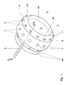
- figure 1 shows a perspective view of an exit ring 1.
- the exit ring 1 comprises a tilted front surface 3, which is facing away from the stream of combustion air/fuel which in operation exits the burner. Facing the stream of combustion air/fuel which exits the cavity 5 of the mixing tube, there is a in rounded inner surface 16.
- This rounded surface 16 gives a breakaway edge which stabilizes and enlarges the back flow zone forming in the downstream region of the burner.
- the exit ring 1 is provided with a pilot burner system for use with pilot gas as well as with a pilot burner system for use with liquid fuel, i.e. with pilot oil.
- a number of holes 4 (16 holes) is provided on the tilted surfaces 3 of the exit ring 1.
- the axis 34 of these holes is substantially perpendicular to the plane of the surface 3. Only one of these holes 4 is being used for pilot oil operation, namely the one that is connected to the tube 8 for pilot oil (the one crossed by the line A-A in fig. 1).
- To supply the pilot fuel with combustion air there is provided particular pathways to guide this air to the holes 4. This air subsequently enters the interior of the exit ring by means of the entrance holes 7.
- Figure 2 shows an axial cut through an exit ring 1 along the line A-A as indicated in figure 1.
- the cut passes through the pilot oil supply system.
- the tube 8 goes straight into the exit ring to end at one of the holes 4.
- the tube 8 terminates in a tilted endplate 15, which is aligned substantially parallel to the surface 3 and substantially orthogonal to the axis 34 of the hole 4.
- Also visible in figure 2 is the position of the backside wall 11 of the combustion chamber 2, which is staggered backwards with respect to the front end of the exit ring 1.
- pilot gas 26 On the bottom side of figure 2, the flow of pilot gas 26 can be seen.
- the pilot gas 26 is supplied by a tube 23 to the exit ring 1 to enter an annular duct (not shown) for pilot gas, which serves to distribute the pilot gas into the annular air channel 10.
- the pilot gas is mixed with the air flowing in the annular air channel 10 and is then, as a mixture of gas/air, exiting the hole 4 into the combustion chamber 2.
- the ducts for the pilot gas 26 alternate with the holes 7 for the air and the axial connections to the annular air channel 10 along the circumference of the exit ring 1.
- FIG. 3 displays a cut through a double cone burner 24 with mixing tube.
- the burner 24 comprises a double cone burner 17 as a first upstream swirl generator capable of swirling a combustion air stream.
- the combustion air stream enters the cavity of the double cone burner 17 via entrance slots 19 provided between the cones.
- Gaseous fuel is usually introduced into the combustion air stream in the region of the entrance slots 19.
- Liquid fuel is generally introduced into the cavity of the burner by means of a central oil nozzle 18 located on the axis 9 of the burner.
- the terminal end of the mixing tube 21 is formed by the exit ring 1.
- the tilted front surface 3 of the exit ring 1 is tilted with respect to the backside wall 11 of the combustion chamber 2 by an angle ⁇ , which is generally in the range of about 25 degrees. Additionally, the rounded inner surface 16 is displayed in detail in this figure.
- FIG. 4 shows in more detail, how the pilot oil 27 is guided to the tilted endplate 15 which terminates the tube 8.
- the tilted endplate is aligned substantially parallel to the tilted surface 3.
- the tilted endplate 15 comprises a hole, i.e. a nozzle 28, through which the pilot oil is ejected first into the hole 4 and then into the combustion chamber 2 in a jet 29.
- the hole 28 may be cylindrical, but also conical shapes are possible opening or closing towards the exit.
- the ratio diameter/length of these bores 28 is preferably chosen in the range of 0.25 to 0.75, and the diameters range between 0.5 to 0.6 or even 0.75.
- turbulences can be introduced in the tube 8, e.g. by inserting a turbulence generator into tube 8.
- FIG 5 shows an arrangement of burners 24 in an annular combustion chamber of a gasturbine.
- Ten burners 24 are arranged on a circle, and each of the burners is equipped with one pilot oil injection nozzle 39.
- the injection positions 39 are arranged in the rotationally symmetric way in the combustion chamber 38. That means that each injection position 39 has the same radial position 43 with respect to the radial position 42 of a burner within the annular combustion chamber 38. If the injection positions 39 are located like this respectively, the oil pilot flame shape 40 overlaps optimally for neighbouring burners due to the outside swirl direction 41 present in such an annular combustion chamber 38. Like this the cross ignition properties in pilot mode are substantially enhanced.
Landscapes
- Engineering & Computer Science (AREA)
- Chemical & Material Sciences (AREA)
- Combustion & Propulsion (AREA)
- Mechanical Engineering (AREA)
- General Engineering & Computer Science (AREA)
- Nozzles For Spraying Of Liquid Fuel (AREA)
- Combustion Of Fluid Fuel (AREA)
- Pressure-Spray And Ultrasonic-Wave- Spray Burners (AREA)
Abstract
A burner (24) is proposed which is useful for operating a heat generator. The proposed
burner comprises: a first upstream swirl generator (17) capable of swirling a
combustion air stream, means for injecting at least one fuel into the combustion air
stream from the upstream swirl generator (17), an exit ring (1) located at the
downstream end of the burner (24) at the edge to the combustion chamber (2) where
the fuel is burnt, and preferentially a mixing section (20, 21) downstream from the
upstream swirl generator (17) having a downstream end, having at least one transfer
duct (20) for transferring downstream a flow of combustion air and fuel formed in the
upstream swirl generator (17), and having a mixing tube (21) downstream from said at
least one transfer duct (20) and receiving said flow from said at least one transfer duct
(20), wherein said to downstream end of said mixing section (20, 21) is bordering the
combustion chamber (2) and is formed by said exit ring (1). Pilot mode operation of
such a burner (24) is advantageously and economically made possible by providing a
pilot burner system (8, 15, 28, 35) in the exit ring (1) for injecting liquid fuel (27) into
the combustion chamber (2). The invention additionally relates to the method of
operation of such a burner as well as to an annular combustion chamber with such
burners (24).
Description
- The present invention relates to a burner useful for operating a heat generator comprising: a first upstream swirl generator capable of swirling a combustion air stream, means for injecting at least one fuel into the combustion air stream from the upstream swirl generator, an exit ring located at the downstream end of the burner at the edge to the combustion chamber where the fuel is burnt.
- Premixed burners are characterized by a particularly low emission of NOx if operated under lean conditions. Correspondingly, these burners are operated under lean conditions at standard load. If the load is reduced, these burners have the tendency to become unstable when the supply with fuel is reduced.
- A premixed burner is e.g. proposed in EP 0 321 809 B1, comprising several conical wall portions which are shifted with respect to each other leaving entrance slots through which the combustion air is entering the interior of the burner. Liquid and gaseous fuels can be burnt in such a premixed burner, preferentially liquid fuel is injected by means of a central fuel nozzle located on the axis of the burner, while gaseous fuels can be added to the stream of combustion air at the entrance slots between the conical wall portions.
- An alternative premixed burner, which is described in e.g. EP 0 704 657 A2, or in EP 0 780 629 A2, additionally comprises a mixing tube located downstream of a burner as described in EP 0 321 809 B1, wherein at the entrance of the mixing tube there are transfer ducts for a controlled entrance of the swirling combustion air into the mixing tube.
- To allow reduction of the fuel supply without the above-mentioned problems, a so-called pilot mode is made possible for such burners by providing particular pilot nozzles at the central fuel nozzle or by providing particularly long central fuel nozzles. Alternatively, as described in EP 0 797 051 A2, pilot mode can be made possible by providing, next to the burner, on the backside wall of the combustion chamber and distanced from the exit of the burner, separate mixing elements for fuel and combustion air which can be used for pilot operation of the burner. Another possibility for pilot operation is described in EP 0 994 300 A1, where a burner according to EP 0 704 657 A2 or EP 0 780 629 A2 is provided with an exit ring comprising swirl generators, and where pilot gas is injected into the combustion chamber into the swirl formed by these swirl generators. Yet another alternative for pilot operation is described in EP 0 931 980 A1, where pilot gas is injected next to the exit ring into the combustion chamber after mixing it with combustion air. Additionally, means for igniting the pilot gas are described in this document.
- The objective problem underlying the present invention is therefore to provide an alternative versatile burner which allows pilot operation. In particular pilot operation should be provided for a burner useful for operating a heat generator comprising: a first upstream swirl generator capable of swirling a combustion air stream, means for injecting at least one fuel into the combustion air stream from the upstream swirl generator, an exit ring located at the downstream end of the burner at the edge to the combustion chamber where the fuel is burnt. An example of such a burner is a double-cone burner as described in EP 0 321 809 B1.
- The present invention solves the above problem by providing a pilot burner system located in or at the exit ring for injecting liquid fuel into the combustion chamber. Surprisingly, it is possible to use the exit ring also for locating a pilot burner system for liquid fuel. It is known to locate pilot burner systems for pilot gas in the exit ring, but so far it has never been envisaged to modify such a pilot burner system for pilot gas to be used with liquid fuel in pilot mode, since problems arising with the enormous heat in these regions under normal load conditions did not allow it. The possibility to use liquid fuel for pilot mode is particularly interesting for industrial gas turbines where flexibility with respect to various fuels is a central issue. Additionally, the use of oil in pilot mode makes ignition easier, as igniting liquid fuel is usually easier than the ignition of pilot gas. Furthermore, in contrast to oil pilot nozzles according to the state-of-the-art, the proposed liquid pilot system does not have to be purged with purging air once the operation is shifted from idle to full load. At full load conditions the oil pilot system can be still used (< 5 % oil pilot) to enhance flame stabilisation. Therefore there is no need to shut these nozzles and by doing so, no purging is necessary. This decreases the time delay between different operation modes. Locating the oil injection on the exit ring and injecting the liquid pilot fuel directly into the combustion chamber reduces the danger of flashback occurrence.
- The object of the present invention is therefore a burner according to
claim 1, as well as a method according to claim 12. - In a first preferred embodiment of the present invention the burner is further characterized in that a mixing section is provided downstream from the upstream swirl generator having a downstream end, having at least one transfer duct for transferring downstream a flow of combustion air and fuel formed in the upstream swirl generator, and having a mixing tube downstream from said at least one transfer duct and receiving said flow from said at least one transfer duct, wherein said downstream end of said mixing section is bordering the combustion chamber and is formed by said exit ring. The pilot burner system can thus be used advantageously also in case of premixed burners with mixing tube, as for example described in EP 0 704 657 A2 or EP 0 780 629 A2.
- Preferably, the liquid fuel is injected in a plane comprising the axis of the mixing tube. The jet of liquid fuel is preferentially tilted away from said axis by an angle in the range of 15 to 60 degree, preferentially by an angle in the range of 25 degrees. It thus proofs advantageous not to direct the jet into the main stream exiting the burner, but rather to direct it away from the axis of the burner.
- Various structures of exit rings can be used for locating such a pilot burner system. However, particularly advantageous are exit rings comprising a conical, tilted front surface facing away from the burner axis to the combustion chamber, and that the liquid fuel is injected through at least one, preferentially only one, hole in said tilted front surface. With respect to the general flow conditions at the exit of the burner, preferentially injection is directed along an axis orthogonal to the tilted front surface. It could be shown that providing one pilot nozzle per burner is sufficient for maintaining stable pilot operation, in particular if the nozzles of neighbouring burners in a combustion chamber are oriented properly with respect to each other.
- According to still another preferred embodiment of the invention, the burner is characterized in that liquid fuel is delivered to the pilot burner system by means of a tube, in that a nozzle is located at the downstream end of said tube, through which the liquid fuel is ejected, and in that means are provided to guide air to holes in the exit ring through which holes the jet generated by said nozzle is entering the combustion chamber. Preferentially said means to guide air to the terminal end of the burner are including an annular air channel in the exit ring. The provision of air flowing around the nozzle and shielding the spray cools down the nozzle surface and prevents its overheating in particular in full load conditions.
- Yet another preferred embodiment of the present invention is characterised in that upstream of said nozzle in the tube there is located means for generating turbulence in the flow of liquid fuel in the tube. These means for generating turbulence increase the opening angle of the jet of liquid fuel, which improves the mixing between combustion air and liquid fuel. Preferentially, said means are provided as at least one turbulence generator with at least two holes through which the liquid fuel has to pass. Like this, turbulence is generated in a particularly easy way within the tube.
- According to another preferred embodiment of the invention, said nozzle is located in a tilted endplate terminating the tube, which endplate is preferentially substantially parallel to the above-mentioned tilted front surface of the exit ring. The endplate can be an end cone extending into the hole downstream of the tube, wherein the axis of the cone is substantially aligned with the axis of the hole. By using a conical endplate, the actual position of the discharge of the liquid fuel out of the nozzle can be moved closer to the exit of the hole in the exit ring, thereby preventing that the jet of fuel is for example deflected by the air shielding the jet pushing it on to a wall of the hole.
- According to a further preferred embodiment of the invention, the exit ring additionally has a second pilot burner system for injecting pilot gas into the combustion chamber, wherein preferentially said second pilot burner system is also located in the exit ring and comprises several injection locations distributed circumferentially around a conical, tilted front surface of the exit ring facing away from the burner axis. The combination of the proposed pilot burner system for liquid fuels with a pilot burner system for pilot gas, which is very often already available in the same exit ring, allows, by means of an easy modification of such a pilot gas system, to enhance the versatility of the burner substantially.
- The present invention additionally relates to an annular combustion chamber of a gasturbine unit, which is characterized in that at least two, preferentially at least ten burners, as described above, are arranged within the combustion chamber. Preferentially, such an annular combustion chamber is characterised in that the burners each have one nozzle for injecting liquid fuel for pilot operation, wherein preferentially the radial position of said nozzle within each burner with respect to the radial position of each burner within the annular combustion chamber is the same for all nozzles/burners. Such an arrangement of the nozzles of the burners in an annular combustion chamber optimizes the stability of pilot operation, since due to the outside swirl direction within the annular combustion chamber, the oil pilot flame shapes of neighbouring burners overlap optimally. Thereby the cross ignition properties can be increased in pilot mode.
- The present invention furthermore relates to a method for operating a burner in a heat generator in pilot mode, wherein the burner has a first upstream swirl generator capable of swirling a combustion air stream, means for injecting at least one fuel into the combustion air stream from the upstream swirl generator, an exit ring located at the downstream end of the burner at the edge to the combustion chamber where the fuel is burnt, and preferentially a mixing section provided downstream from the upstream swirl generator having a downstream end, having at least one transfer duct for transferring downstream a flow of combustion air and fuel formed in the upstream swirl generator, and having a mixing tube downstream from said at least one transfer duct and receiving said flow from said at least one transfer duct, wherein said downstream end of said mixing section is bordering the combustion chamber and is formed by said exit ring. The method is characterized in that liquid fuel is injected from the exit ring into the combustion chamber. Preferentially, a burner as it is described above is used.
- Additionally, a method for operating an annular combustion chamber of a gasturbine unit in pilot mode is proposed, which is characterized in that an annular combustion chamber as described above is used, and in that each of the nozzles is substantially equally supplied with liquid fuel.
- Further embodiments of the present invention are outlined in the dependent claims.
- In the accompanying drawings preferred embodiments of the invention are shown in which:
- figure 1
- shows a perspective view of an exit ring;
- figure 2
- shows an axial cut along the line A-A in figure 1, i.e. in a position where there is a tube for pilot oil;
- figure 3
- shows a schematic, axial cut through a double cone burner with mixing tube;
- figure 4
- shows in detail the path of pilot oil in an exit ring including the jet of oil;
- figure 5
- shows a circular arrangement of burners in an annular combustion chamber displaying the relative positioning of the pilot oil injection.
- Referring to the drawings, which are for the purpose of illustrating the present preferred embodiments of the invention and not for the purpose of limiting the same, figure 1 shows a perspective view of an
exit ring 1. On the lower right-hand side, there is, if the burner is mounted, thecombustion chamber 2. On the upper left-hand side, a mixing tube is located. Theexit ring 1 comprises a tiltedfront surface 3, which is facing away from the stream of combustion air/fuel which in operation exits the burner. Facing the stream of combustion air/fuel which exits thecavity 5 of the mixing tube, there is a in roundedinner surface 16. Thisrounded surface 16 gives a breakaway edge which stabilizes and enlarges the back flow zone forming in the downstream region of the burner. For more details, reference is made to EP 0 780 629 A2, which disclosure is incorporated herein. - The
exit ring 1 is provided with a pilot burner system for use with pilot gas as well as with a pilot burner system for use with liquid fuel, i.e. with pilot oil. For the purpose of operating the burner with pilot gas, a number of holes 4 (16 holes) is provided on the tiltedsurfaces 3 of theexit ring 1. Theaxis 34 of these holes is substantially perpendicular to the plane of thesurface 3. Only one of theseholes 4 is being used for pilot oil operation, namely the one that is connected to thetube 8 for pilot oil (the one crossed by the line A-A in fig. 1). To supply the pilot fuel with combustion air, there is provided particular pathways to guide this air to theholes 4. This air subsequently enters the interior of the exit ring by means of the entrance holes 7. - Figure 2 shows an axial cut through an
exit ring 1 along the line A-A as indicated in figure 1. On the top, the cut passes through the pilot oil supply system. Thetube 8 goes straight into the exit ring to end at one of theholes 4. In the terminal region of theexit ring 1, i.e. underneath the tiltedsurface 3, there is anannular air channel 10 from which theholes 4 branch off. Thetube 8 terminates in a tiltedendplate 15, which is aligned substantially parallel to thesurface 3 and substantially orthogonal to theaxis 34 of thehole 4. Also visible in figure 2 is the position of thebackside wall 11 of thecombustion chamber 2, which is staggered backwards with respect to the front end of theexit ring 1. - On the bottom side of figure 2, the flow of
pilot gas 26 can be seen. Thepilot gas 26 is supplied by atube 23 to theexit ring 1 to enter an annular duct (not shown) for pilot gas, which serves to distribute the pilot gas into theannular air channel 10. The pilot gas is mixed with the air flowing in theannular air channel 10 and is then, as a mixture of gas/air, exiting thehole 4 into thecombustion chamber 2. The ducts for thepilot gas 26 alternate with theholes 7 for the air and the axial connections to theannular air channel 10 along the circumference of theexit ring 1. - Figure 3 displays a cut through a
double cone burner 24 with mixing tube. Such a burner is for example described in EP 0 780 629 A2. Theburner 24 comprises adouble cone burner 17 as a first upstream swirl generator capable of swirling a combustion air stream. The combustion air stream enters the cavity of thedouble cone burner 17 viaentrance slots 19 provided between the cones. Gaseous fuel is usually introduced into the combustion air stream in the region of theentrance slots 19. Liquid fuel is generally introduced into the cavity of the burner by means of acentral oil nozzle 18 located on theaxis 9 of the burner. Downstream of thedouble cone burner 17 there istransfer ducts 20, which serve to guide the swirl generated in thedouble cone burner 17 into the mixingtube 21. The terminal end of the mixingtube 21 is formed by theexit ring 1. The tiltedfront surface 3 of theexit ring 1 is tilted with respect to thebackside wall 11 of thecombustion chamber 2 by an angle α, which is generally in the range of about 25 degrees. Additionally, the roundedinner surface 16 is displayed in detail in this figure. - Figure 4 shows in more detail, how the
pilot oil 27 is guided to the tiltedendplate 15 which terminates thetube 8. The tilted endplate is aligned substantially parallel to the tiltedsurface 3. In a central position, aligned with theaxis 34 of thehole 4, the tiltedendplate 15 comprises a hole, i.e. anozzle 28, through which the pilot oil is ejected first into thehole 4 and then into thecombustion chamber 2 in ajet 29. Thehole 28 may be cylindrical, but also conical shapes are possible opening or closing towards the exit. The ratio diameter/length of thesebores 28 is preferably chosen in the range of 0.25 to 0.75, and the diameters range between 0.5 to 0.6 or even 0.75. To increase the opening angle of thejet 29, turbulences can be introduced in thetube 8, e.g. by inserting a turbulence generator intotube 8. - Figure 5 shows an arrangement of
burners 24 in an annular combustion chamber of a gasturbine. Tenburners 24 are arranged on a circle, and each of the burners is equipped with one pilotoil injection nozzle 39. To have optimum cross ignition properties in pilot mode, the injection positions 39 are arranged in the rotationally symmetric way in thecombustion chamber 38. That means that eachinjection position 39 has the sameradial position 43 with respect to theradial position 42 of a burner within theannular combustion chamber 38. If the injection positions 39 are located like this respectively, the oilpilot flame shape 40 overlaps optimally for neighbouring burners due to theoutside swirl direction 41 present in such anannular combustion chamber 38. Like this the cross ignition properties in pilot mode are substantially enhanced. -
- 1
- exit ring
- 2
- combustion chamber
- 3
- tilted front surface of 1
- 4
- holes for pilot flame
- 5
- cavity of mixing tube
- 7
- entrance holes for air supply
- 8
- tube for pilot oil
- 9
- axis of the burner
- 10
- annular air channel
- 11
- backside wall of the combustion chamber
- 15
- tilted endplate of 8
- 16
- rounded inner surface of 1
- 17
- double cone burner, swirl generator
- 18
- central oil nozzle
- 19
- entrance slot between the cones of 17
- 20
- transfer ducts
- 21
- mixing tube, mixing length
- 23
- tube for pilot gas
- 24
- double cone burner with mixing tube
- 25
- air
- 26
- pilot gas
- 27
- pilot oil
- 28
- nozzle in 15
- 29
- jet of 26 injected into combustion chamber
- 31
- carrier plate of 30
- 32
- hole in 30
- 33
- central portion of 30
- 34
- axis of 4
- 35
- tilted end cone of 8
- 36
- radial shift of 8
- 37
- changed air channel geometry
- 38
- annular combustion chamber
- 39
- position of the pilot oil injection
- 40
- oil pilot flame shape
- 41
- outside swirl direction
- 42
- radial position of a burner within the annular combustion chamber
- 43
- radial position of a pilot oil injection within one burner
- α
- tilt angle of 3
- R
- radius of 16
- L
- length of mixing tube
- T
- thickness of 15
- A
- displacement of 30
- B
- inner diameter of 8
- C
- thickness of 30
- D
- diameter of 28
- E
- thickness of carrier plate
- F
- diameter of 32
Claims (14)
- A burner (24) useful for operating a heat generator comprising:a first upstream swirl generator (17) capable of swirling a combustion air stream,means for injecting at least one fuel into the combustion air stream from the upstream swirl generator (17),an exit ring (1) located at the downstream end of the burner (24) at the edge to the combustion chamber (2) where the fuel is burnt,
characterized in that
a pilot burner system (8, 15, 28, 35) is provided in the exit ring (1) for injecting liquid fuel (27) into the combustion chamber (2). - Burner (24) according to claim 1, characterized in that a mixing section (20, 21) is provided downstream from the upstream swirl generator (17) having a downstream end, having at least one transfer duct (20) for transferring downstream a flow of combustion air and fuel formed in the upstream swirl generator (17), and having a mixing tube (21) downstream from said at least one transfer duct (20) and receiving said flow from said at least one transfer duct (20), wherein said downstream end of said mixing section (20, 21) is bordering the combustion chamber (2) and is formed by said exit ring (1).
- Burner (24) according to claim 2, characterized in that the liquid fuel (27) is injected (29) in a plane comprising the axis (9) of the mixing tube (21), wherein preferably the jet (29) of liquid fuel is tilted away from said axis (9) by an angle in the range of 15 to 60 degree, preferentially by an angle in the range of 25 degrees.
- Burner (24) according to claim 3, characterized in that the exit ring (1) comprises a conical, tilted front surface (3) facing away from the burner axis (9) to the combustion chamber (2), and that the liquid fuel (27) is injected through at least one, preferentially only one, hole (4) in said tilted front surface (3), wherein preferentially injection (29) is directed along an axis (34) orthogonal to the tilted front surface (3).
- Burner (24) according to one of the claims 2 to 4, characterized in that liquid fuel (27) is delivered to the pilot burner system (8, 15, 28, 35) by means of a tube (8), in that a nozzle (28) is located at the downstream end of said tube (8), through which the liquid fuel (27) is ejected, and in that means (7,10), preferentially including an annular air channel (10) in the exit ring (1), are provided to guide air (25) to holes (4) in the exit ring (1) through which holes (4) the jet (29) generated by said nozzle (28) is entering the combustion chamber (2).
- Burner (24) according to claim 5, characterized in that upstream of said nozzle (28) in the tube (8) there is located means (30) for generating turbulence in the flow of liquid fuel (27) in the tube (8), wherein preferentially said means (30) are provided as at least one turbulence generator with at least two holes (32) through which the liquid fuel (27) has to pass.
- Burner (24) according to claim 4 and one of the claims 5 or 6, characterized in that said nozzle (28) is located in a tilted endplate (15, 35) terminating the tube (8), which endplate (15, 35) is preferentially substantially parallel to the tilted front surface (3).
- Burner (24) according to claim 7, characterized in that the endplate (35) is an end cone (35) extending into the hole (4) downstream of the tube (8) wherein the axis of the cone is substantially aligned with the axis (34) of the hole (4).
- Burner (24) according to one of the preceding claims, characterized in that the exit ring (1) additionally has a second pilot burner system (23) for injecting pilot gas (26) into the combustion chamber (2), wherein preferentially said second pilot burner system (23) is also provided in the exit ring (1) and comprises several injection locations distributed circumferentially around a conical, tilted front surface (3) of the exit ring (1) facing away from the burner axis (9).
- Annular combustion chamber (38) of a gasturbine unit, characterized in that at least 2, preferentially at least 10 burners (24) according to one of the claims 1 to 9 are arranged within the combustion chamber (38).
- Annular combustion chamber (38) according to claim 10, characterized in that the burners (24) each have one nozzle (28) for injecting liquid fuel (27) for pilot operation, wherein preferentially the radial position (43) of said nozzle (28) within each burner (24) with respect to the radial position (42) of each burner (24) within the annular combustion chamber (38) is the same for all nozzles (28).
- Method for operating a burner (24) in a heat generator in pilot mode, wherein the burner (24) has
a first upstream swirl generator (17) capable of swirling a combustion air stream,
means for injecting at least one fuel into the combustion air stream from the upstream swirl generator (17),
an exit ring (1) located at the downstream end of the burner (24) at the edge to the combustion chamber (2) where the fuel is burnt,
and preferentially a mixing section (20, 21) provided downstream from the upstream swirl generator (17) having a downstream end, having at least one transfer duct (20) for transferring downstream a flow of combustion air and fuel formed in the upstream swirl generator (17), and having a mixing tube (21) downstream from said at least one transfer duct (20) and receiving said flow from said at least one transfer duct (20), wherein said downstream end of said mixing section (20, 21) is bordering the combustion chamber (2) and is formed by said exit ring (1),
characterized in that
liquid fuel (27) is injected from the exit ring (1) into the combustion chamber (2). - Method according to claim 12, characterized in that a burner according to one of the claims 1 to 9 is used.
- Method for operating an annular combustion chamber (38) of a gasturbine unit in pilot mode, characterized in that an annular combustion chamber according to claim 12 is used, and in that each of the nozzles (28) is substantially equally supplied with liquid fuel (27).
Priority Applications (7)
| Application Number | Priority Date | Filing Date | Title |
|---|---|---|---|
| EP02405684A EP1389713A1 (en) | 2002-08-12 | 2002-08-12 | Premixed exit ring pilot burner |
| AU2003246511A AU2003246511A1 (en) | 2002-08-12 | 2003-08-05 | Premixed exit ring pilot burner |
| CNB038187736A CN1316198C (en) | 2002-08-12 | 2003-08-05 | Premixed exit ring pilot burner |
| PCT/CH2003/000530 WO2004015332A1 (en) | 2002-08-12 | 2003-08-05 | Premixed exit ring pilot burner |
| EP03783891A EP1529180B1 (en) | 2002-08-12 | 2003-08-05 | Premixed exit ring pilot burner |
| DE60335377T DE60335377D1 (en) | 2002-08-12 | 2003-08-05 | CURRENT PILOTRING BURNER FOR PRE-MIXING BURNER |
| US11/036,107 US7140183B2 (en) | 2002-08-12 | 2005-01-18 | Premixed exit ring pilot burner |
Applications Claiming Priority (1)
| Application Number | Priority Date | Filing Date | Title |
|---|---|---|---|
| EP02405684A EP1389713A1 (en) | 2002-08-12 | 2002-08-12 | Premixed exit ring pilot burner |
Publications (1)
| Publication Number | Publication Date |
|---|---|
| EP1389713A1 true EP1389713A1 (en) | 2004-02-18 |
Family
ID=30470351
Family Applications (2)
| Application Number | Title | Priority Date | Filing Date |
|---|---|---|---|
| EP02405684A Withdrawn EP1389713A1 (en) | 2002-08-12 | 2002-08-12 | Premixed exit ring pilot burner |
| EP03783891A Expired - Lifetime EP1529180B1 (en) | 2002-08-12 | 2003-08-05 | Premixed exit ring pilot burner |
Family Applications After (1)
| Application Number | Title | Priority Date | Filing Date |
|---|---|---|---|
| EP03783891A Expired - Lifetime EP1529180B1 (en) | 2002-08-12 | 2003-08-05 | Premixed exit ring pilot burner |
Country Status (6)
| Country | Link |
|---|---|
| US (1) | US7140183B2 (en) |
| EP (2) | EP1389713A1 (en) |
| CN (1) | CN1316198C (en) |
| AU (1) | AU2003246511A1 (en) |
| DE (1) | DE60335377D1 (en) |
| WO (1) | WO2004015332A1 (en) |
Cited By (10)
| Publication number | Priority date | Publication date | Assignee | Title |
|---|---|---|---|---|
| WO2007110298A1 (en) * | 2006-03-27 | 2007-10-04 | Alstom Technology Ltd | Burner for the operation of a heat generator |
| EP2110601A1 (en) * | 2008-04-15 | 2009-10-21 | Siemens Aktiengesellschaft | Burner |
| EP1870581A4 (en) * | 2005-03-18 | 2010-07-14 | Kawasaki Heavy Ind Ltd | GAS TURBINE COMBUSTION CHAMBER AND IGNITION METHOD THEREOF |
| WO2011026982A1 (en) * | 2009-09-07 | 2011-03-10 | Alstom Technology Ltd | Method for switching over a gas turbine burner operation from liquid to gas fuel and vice-versa |
| US8511097B2 (en) | 2005-03-18 | 2013-08-20 | Kawasaki Jukogyo Kabushiki Kaisha | Gas turbine combustor and ignition method of igniting fuel mixture in the same |
| EP2221542A3 (en) * | 2009-02-19 | 2014-06-25 | General Electric Company | Systems, methods, and apparatus providing a secondary fuel nozzle assembly |
| WO2016188954A1 (en) * | 2015-05-25 | 2016-12-01 | Nuovo Pignone Tecnologie Srl | Gas turbine fuel nozzle with integrated flame ionization sensor and gas turbine engine |
| CN107024078A (en) * | 2012-02-01 | 2017-08-08 | 振兴电子有限责任公司 | Method and apparatus for drying electronic installation |
| EP3620718A1 (en) | 2018-09-07 | 2020-03-11 | Siemens Aktiengesellschaft | Gas turbine burner with pilot fuel-air mixing |
| US10859272B2 (en) | 2016-01-15 | 2020-12-08 | Siemens Aktiengesellschaft | Combustor for a gas turbine |
Families Citing this family (24)
| Publication number | Priority date | Publication date | Assignee | Title |
|---|---|---|---|---|
| WO2006069861A1 (en) * | 2004-12-23 | 2006-07-06 | Alstom Technology Ltd | Premix burner comprising a mixing section |
| CN100443805C (en) * | 2005-09-29 | 2008-12-17 | 北京航空航天大学 | Evaporation tube type micro engine combustor |
| DE102005062079A1 (en) * | 2005-12-22 | 2007-07-12 | Rolls-Royce Deutschland Ltd & Co Kg | Magervormic burner with a nebulizer lip |
| DE102006015529A1 (en) * | 2006-03-31 | 2007-10-04 | Alstom Technology Ltd. | Burner system with staged fuel injection |
| EP2058590B1 (en) * | 2007-11-09 | 2016-03-23 | Alstom Technology Ltd | Method for operating a burner |
| CN101910723B (en) * | 2007-11-27 | 2013-07-24 | 阿尔斯通技术有限公司 | Device for burning hydrogen in a premix burner |
| EP2090830B1 (en) * | 2008-02-13 | 2017-01-18 | General Electric Technology GmbH | Fuel supply arrangement |
| ES2389998T3 (en) * | 2008-03-25 | 2012-11-05 | Electrolux Home Products Corporation N.V. | Cooking hob with improved gas burner |
| US7757491B2 (en) * | 2008-05-09 | 2010-07-20 | General Electric Company | Fuel nozzle for a gas turbine engine and method for fabricating the same |
| US8220269B2 (en) * | 2008-09-30 | 2012-07-17 | Alstom Technology Ltd. | Combustor for a gas turbine engine with effusion cooled baffle |
| US8220271B2 (en) * | 2008-09-30 | 2012-07-17 | Alstom Technology Ltd. | Fuel lance for a gas turbine engine including outer helical grooves |
| US8413446B2 (en) * | 2008-12-10 | 2013-04-09 | Caterpillar Inc. | Fuel injector arrangement having porous premixing chamber |
| US8607568B2 (en) | 2009-05-14 | 2013-12-17 | General Electric Company | Dry low NOx combustion system with pre-mixed direct-injection secondary fuel nozzle |
| CH703655A1 (en) * | 2010-08-27 | 2012-02-29 | Alstom Technology Ltd | Premix FOR A GAS TURBINE. |
| EP2650612A1 (en) * | 2012-04-10 | 2013-10-16 | Siemens Aktiengesellschaft | Burner |
| EP2743588A1 (en) * | 2012-12-11 | 2014-06-18 | Siemens Aktiengesellschaft | Recessed fuel injector positioning |
| US9371998B2 (en) * | 2013-05-13 | 2016-06-21 | Solar Turbines Incorporated | Shrouded pilot liquid tube |
| CN107084388B (en) * | 2017-04-24 | 2023-07-14 | 东莞市兴伟达节能环保科技有限公司 | A mixed atomization cracking burner and its mixed combustion method |
| US10982593B2 (en) * | 2017-06-16 | 2021-04-20 | General Electric Company | System and method for combusting liquid fuel in a gas turbine combustor with staged combustion |
| EP3425281B1 (en) * | 2017-07-04 | 2020-09-02 | General Electric Company | Pilot nozzle with inline premixing |
| JP7244526B2 (en) * | 2017-09-25 | 2023-03-22 | ベイジン ゾンユー トップサン エナジー テクノロジー カンパニー リミテッド | Burner and how to use it |
| RU2755240C2 (en) * | 2017-12-26 | 2021-09-14 | Ансальдо Энергия Свитзерленд Аг | Burner for combustion chamber of gas turbine power plant, combustion chamber of gas turbine power plant containing such burner, and gas turbine power plant containing such combustion chamber |
| CN110389193B (en) * | 2019-07-15 | 2022-09-16 | 江西科技师范大学 | Simulating combustion environment device II for stabilizing combustion improver |
| DE102023132050A1 (en) * | 2023-11-17 | 2025-05-22 | Man Energy Solutions Se | Gas turbine burner |
Citations (11)
| Publication number | Priority date | Publication date | Assignee | Title |
|---|---|---|---|---|
| EP0321809B1 (en) | 1987-12-21 | 1991-05-15 | BBC Brown Boveri AG | Process for combustion of liquid fuel in a burner |
| EP0704657A2 (en) | 1994-10-01 | 1996-04-03 | ABB Management AG | Burner |
| EP0780629A2 (en) | 1995-12-21 | 1997-06-25 | ABB Research Ltd. | Burner for a heat generator |
| EP0797051A2 (en) | 1996-03-20 | 1997-09-24 | Abb Research Ltd. | Burner for a heat generator |
| EP0833104A2 (en) * | 1996-09-25 | 1998-04-01 | Abb Research Ltd. | Burner for operating a combustion chamber |
| US5794449A (en) * | 1995-06-05 | 1998-08-18 | Allison Engine Company, Inc. | Dry low emission combustor for gas turbine engines |
| EP0931980A1 (en) | 1998-01-23 | 1999-07-28 | Abb Research Ltd. | Burner for operating a heat generator |
| EP0994300A1 (en) | 1998-10-14 | 2000-04-19 | Abb Research Ltd. | Burner for operating a heat generator |
| EP1058062A1 (en) * | 1999-05-31 | 2000-12-06 | Nuovo Pignone Holding S.P.A. | Device for connection of a nozzle of pre-mixing chamber of a gas turbine, to a housing of the pre-mixing chamber |
| EP1070914A1 (en) * | 1999-07-22 | 2001-01-24 | ABB Alstom Power (Schweiz) AG | Premix burner |
| EP1199522A2 (en) * | 2000-10-20 | 2002-04-24 | AERO & INDUSTRIAL TECHNOLOGY LTD. | Fuel injectors |
Family Cites Families (3)
| Publication number | Priority date | Publication date | Assignee | Title |
|---|---|---|---|---|
| EP0909921B1 (en) * | 1997-10-14 | 2003-01-02 | Alstom | Burner for operating a heat generator |
| EP0987493B1 (en) * | 1998-09-16 | 2003-08-06 | Abb Research Ltd. | Burner for a heat generator |
| IT1313547B1 (en) * | 1999-09-23 | 2002-07-24 | Nuovo Pignone Spa | PRE-MIXING CHAMBER FOR GAS TURBINES |
-
2002
- 2002-08-12 EP EP02405684A patent/EP1389713A1/en not_active Withdrawn
-
2003
- 2003-08-05 AU AU2003246511A patent/AU2003246511A1/en not_active Abandoned
- 2003-08-05 EP EP03783891A patent/EP1529180B1/en not_active Expired - Lifetime
- 2003-08-05 CN CNB038187736A patent/CN1316198C/en not_active Expired - Fee Related
- 2003-08-05 WO PCT/CH2003/000530 patent/WO2004015332A1/en not_active Ceased
- 2003-08-05 DE DE60335377T patent/DE60335377D1/en not_active Expired - Lifetime
-
2005
- 2005-01-18 US US11/036,107 patent/US7140183B2/en not_active Expired - Lifetime
Patent Citations (11)
| Publication number | Priority date | Publication date | Assignee | Title |
|---|---|---|---|---|
| EP0321809B1 (en) | 1987-12-21 | 1991-05-15 | BBC Brown Boveri AG | Process for combustion of liquid fuel in a burner |
| EP0704657A2 (en) | 1994-10-01 | 1996-04-03 | ABB Management AG | Burner |
| US5794449A (en) * | 1995-06-05 | 1998-08-18 | Allison Engine Company, Inc. | Dry low emission combustor for gas turbine engines |
| EP0780629A2 (en) | 1995-12-21 | 1997-06-25 | ABB Research Ltd. | Burner for a heat generator |
| EP0797051A2 (en) | 1996-03-20 | 1997-09-24 | Abb Research Ltd. | Burner for a heat generator |
| EP0833104A2 (en) * | 1996-09-25 | 1998-04-01 | Abb Research Ltd. | Burner for operating a combustion chamber |
| EP0931980A1 (en) | 1998-01-23 | 1999-07-28 | Abb Research Ltd. | Burner for operating a heat generator |
| EP0994300A1 (en) | 1998-10-14 | 2000-04-19 | Abb Research Ltd. | Burner for operating a heat generator |
| EP1058062A1 (en) * | 1999-05-31 | 2000-12-06 | Nuovo Pignone Holding S.P.A. | Device for connection of a nozzle of pre-mixing chamber of a gas turbine, to a housing of the pre-mixing chamber |
| EP1070914A1 (en) * | 1999-07-22 | 2001-01-24 | ABB Alstom Power (Schweiz) AG | Premix burner |
| EP1199522A2 (en) * | 2000-10-20 | 2002-04-24 | AERO & INDUSTRIAL TECHNOLOGY LTD. | Fuel injectors |
Cited By (19)
| Publication number | Priority date | Publication date | Assignee | Title |
|---|---|---|---|---|
| EP1870581A4 (en) * | 2005-03-18 | 2010-07-14 | Kawasaki Heavy Ind Ltd | GAS TURBINE COMBUSTION CHAMBER AND IGNITION METHOD THEREOF |
| US8511097B2 (en) | 2005-03-18 | 2013-08-20 | Kawasaki Jukogyo Kabushiki Kaisha | Gas turbine combustor and ignition method of igniting fuel mixture in the same |
| WO2007110298A1 (en) * | 2006-03-27 | 2007-10-04 | Alstom Technology Ltd | Burner for the operation of a heat generator |
| US7972133B2 (en) | 2006-03-27 | 2011-07-05 | Alstom Technology Ltd. | Burner for the operation of a heat generator and method of use |
| EP2110601A1 (en) * | 2008-04-15 | 2009-10-21 | Siemens Aktiengesellschaft | Burner |
| WO2009127606A1 (en) * | 2008-04-15 | 2009-10-22 | Siemens Aktiengesellschaft | Burner |
| US9074764B2 (en) | 2008-04-15 | 2015-07-07 | Siemens Aktiengesellschaft | Burner having a pilot burner system with swirler wings and a plurality of outlet nozzles |
| CN102007341A (en) * | 2008-04-15 | 2011-04-06 | 西门子公司 | Burner |
| EP2221542A3 (en) * | 2009-02-19 | 2014-06-25 | General Electric Company | Systems, methods, and apparatus providing a secondary fuel nozzle assembly |
| WO2011026982A1 (en) * | 2009-09-07 | 2011-03-10 | Alstom Technology Ltd | Method for switching over a gas turbine burner operation from liquid to gas fuel and vice-versa |
| EP2299091A1 (en) * | 2009-09-07 | 2011-03-23 | Alstom Technology Ltd | Method for Switching over a Gas Turbine Burner Operation from Liquid to Gas Fuel and Vice-Versa |
| CN107024078A (en) * | 2012-02-01 | 2017-08-08 | 振兴电子有限责任公司 | Method and apparatus for drying electronic installation |
| CN107024078B (en) * | 2012-02-01 | 2021-03-26 | 振兴电子有限责任公司 | Method and apparatus for drying electronic devices |
| WO2016188954A1 (en) * | 2015-05-25 | 2016-12-01 | Nuovo Pignone Tecnologie Srl | Gas turbine fuel nozzle with integrated flame ionization sensor and gas turbine engine |
| US11054135B2 (en) | 2015-05-25 | 2021-07-06 | Nuovo Pignone Tecnologie Srl | Gas turbine fuel nozzle with integrated flame ionization sensor and gas turbine engine |
| US10859272B2 (en) | 2016-01-15 | 2020-12-08 | Siemens Aktiengesellschaft | Combustor for a gas turbine |
| EP3403028B1 (en) * | 2016-01-15 | 2021-02-24 | Siemens Energy Global GmbH & Co. KG | Combustor for a gas turbine |
| EP3620718A1 (en) | 2018-09-07 | 2020-03-11 | Siemens Aktiengesellschaft | Gas turbine burner with pilot fuel-air mixing |
| WO2020048880A1 (en) | 2018-09-07 | 2020-03-12 | Siemens Aktiengesellschaft | Gas turbine burner with pilot fuel-air mixing |
Also Published As
| Publication number | Publication date |
|---|---|
| WO2004015332A1 (en) | 2004-02-19 |
| US20050164138A1 (en) | 2005-07-28 |
| EP1529180A1 (en) | 2005-05-11 |
| DE60335377D1 (en) | 2011-01-27 |
| CN1675500A (en) | 2005-09-28 |
| CN1316198C (en) | 2007-05-16 |
| EP1529180B1 (en) | 2010-12-15 |
| AU2003246511A1 (en) | 2004-02-25 |
| US7140183B2 (en) | 2006-11-28 |
Similar Documents
| Publication | Publication Date | Title |
|---|---|---|
| EP1529180B1 (en) | Premixed exit ring pilot burner | |
| US6092363A (en) | Low Nox combustor having dual fuel injection system | |
| EP1323982B1 (en) | Fuel nozzle for a gas turbine engine | |
| US7143583B2 (en) | Gas turbine combustor, combustion method of the gas turbine combustor, and method of remodeling a gas turbine combustor | |
| KR100239082B1 (en) | Core Structure for Gas Turbine Combustor and Dual Combustor | |
| JP3672597B2 (en) | Fuel lance for liquid and / or gaseous fuel | |
| KR101563526B1 (en) | Gas turbine combustion system | |
| US5435126A (en) | Fuel nozzle for a turbine having dual capability for diffusion and premix combustion and methods of operation | |
| US6155820A (en) | Burner for operating a heat generator | |
| JP4930921B2 (en) | Fuel injector for combustion chamber of gas turbine engine | |
| US7406827B2 (en) | Apparatus for injecting a fuel-air mixture into a combustion chamber | |
| JP6812240B2 (en) | Air Fuel Premixer for Low Emission Turbine Combustors | |
| EP0722065B1 (en) | Fuel injector arrangement for gas-or liquid-fuelled turbine | |
| CN1571905A (en) | Burner for synthesis gas | |
| EP4379261B1 (en) | Combustion nozzle and combustor | |
| US5249955A (en) | Burner and ignitor arrangement | |
| US20040055307A1 (en) | Premix burner and method of operation | |
| CN1957208B (en) | Staged premix burner | |
| JPH09178120A (en) | Premixing type burner | |
| GB2348948A (en) | A fuel lance for spraying liquid and/or gaseous fuels into a combustion chamber | |
| US5807097A (en) | Cone burner | |
| US6152726A (en) | Burner for operating a heat generator | |
| JP3392633B2 (en) | Combustor | |
| KR101546216B1 (en) | Premix burner of the multi-cone type for a gas turbine | |
| US5954490A (en) | Burner for operating a heat generator |
Legal Events
| Date | Code | Title | Description |
|---|---|---|---|
| PUAI | Public reference made under article 153(3) epc to a published international application that has entered the european phase |
Free format text: ORIGINAL CODE: 0009012 |
|
| AK | Designated contracting states |
Kind code of ref document: A1 Designated state(s): AT BE BG CH CY CZ DE DK EE ES FI FR GB GR IE IT LI LU MC NL PT SE SK TR |
|
| AX | Request for extension of the european patent |
Extension state: AL LT LV MK RO SI |
|
| RAP1 | Party data changed (applicant data changed or rights of an application transferred) |
Owner name: ALSTOM TECHNOLOGY LTD |
|
| 17P | Request for examination filed |
Effective date: 20040806 |
|
| AKX | Designation fees paid |
Designated state(s): DE GB |
|
| STAA | Information on the status of an ep patent application or granted ep patent |
Free format text: STATUS: THE APPLICATION IS DEEMED TO BE WITHDRAWN |
|
| 18D | Application deemed to be withdrawn |
Effective date: 20060301 |