EP1389674A1 - Diesel engine exhaust purifying device - Google Patents
Diesel engine exhaust purifying device Download PDFInfo
- Publication number
- EP1389674A1 EP1389674A1 EP02730692A EP02730692A EP1389674A1 EP 1389674 A1 EP1389674 A1 EP 1389674A1 EP 02730692 A EP02730692 A EP 02730692A EP 02730692 A EP02730692 A EP 02730692A EP 1389674 A1 EP1389674 A1 EP 1389674A1
- Authority
- EP
- European Patent Office
- Prior art keywords
- exhaust gas
- temperature region
- engine
- gas temperature
- intake air
- Prior art date
- Legal status (The legal status is an assumption and is not a legal conclusion. Google has not performed a legal analysis and makes no representation as to the accuracy of the status listed.)
- Withdrawn
Links
Images



Classifications
-
- F—MECHANICAL ENGINEERING; LIGHTING; HEATING; WEAPONS; BLASTING
- F01—MACHINES OR ENGINES IN GENERAL; ENGINE PLANTS IN GENERAL; STEAM ENGINES
- F01N—GAS-FLOW SILENCERS OR EXHAUST APPARATUS FOR MACHINES OR ENGINES IN GENERAL; GAS-FLOW SILENCERS OR EXHAUST APPARATUS FOR INTERNAL-COMBUSTION ENGINES
- F01N13/00—Exhaust or silencing apparatus characterised by constructional features
- F01N13/02—Exhaust or silencing apparatus characterised by constructional features having two or more separate silencers in series
-
- F—MECHANICAL ENGINEERING; LIGHTING; HEATING; WEAPONS; BLASTING
- F01—MACHINES OR ENGINES IN GENERAL; ENGINE PLANTS IN GENERAL; STEAM ENGINES
- F01L—CYCLICALLY OPERATING VALVES FOR MACHINES OR ENGINES
- F01L1/00—Valve-gear or valve arrangements, e.g. lift-valve gear
- F01L1/34—Valve-gear or valve arrangements, e.g. lift-valve gear characterised by the provision of means for changing the timing of the valves without changing the duration of opening and without affecting the magnitude of the valve lift
-
- F—MECHANICAL ENGINEERING; LIGHTING; HEATING; WEAPONS; BLASTING
- F01—MACHINES OR ENGINES IN GENERAL; ENGINE PLANTS IN GENERAL; STEAM ENGINES
- F01L—CYCLICALLY OPERATING VALVES FOR MACHINES OR ENGINES
- F01L9/00—Valve-gear or valve arrangements actuated non-mechanically
- F01L9/20—Valve-gear or valve arrangements actuated non-mechanically by electric means
-
- F—MECHANICAL ENGINEERING; LIGHTING; HEATING; WEAPONS; BLASTING
- F01—MACHINES OR ENGINES IN GENERAL; ENGINE PLANTS IN GENERAL; STEAM ENGINES
- F01N—GAS-FLOW SILENCERS OR EXHAUST APPARATUS FOR MACHINES OR ENGINES IN GENERAL; GAS-FLOW SILENCERS OR EXHAUST APPARATUS FOR INTERNAL-COMBUSTION ENGINES
- F01N3/00—Exhaust or silencing apparatus having means for purifying, rendering innocuous, or otherwise treating exhaust
- F01N3/02—Exhaust or silencing apparatus having means for purifying, rendering innocuous, or otherwise treating exhaust for cooling, or for removing solid constituents of, exhaust
- F01N3/021—Exhaust or silencing apparatus having means for purifying, rendering innocuous, or otherwise treating exhaust for cooling, or for removing solid constituents of, exhaust by means of filters
- F01N3/023—Exhaust or silencing apparatus having means for purifying, rendering innocuous, or otherwise treating exhaust for cooling, or for removing solid constituents of, exhaust by means of filters using means for regenerating the filters, e.g. by burning trapped particles
- F01N3/0231—Exhaust or silencing apparatus having means for purifying, rendering innocuous, or otherwise treating exhaust for cooling, or for removing solid constituents of, exhaust by means of filters using means for regenerating the filters, e.g. by burning trapped particles using special exhaust apparatus upstream of the filter for producing nitrogen dioxide, e.g. for continuous filter regeneration systems [CRT]
-
- F—MECHANICAL ENGINEERING; LIGHTING; HEATING; WEAPONS; BLASTING
- F01—MACHINES OR ENGINES IN GENERAL; ENGINE PLANTS IN GENERAL; STEAM ENGINES
- F01N—GAS-FLOW SILENCERS OR EXHAUST APPARATUS FOR MACHINES OR ENGINES IN GENERAL; GAS-FLOW SILENCERS OR EXHAUST APPARATUS FOR INTERNAL-COMBUSTION ENGINES
- F01N3/00—Exhaust or silencing apparatus having means for purifying, rendering innocuous, or otherwise treating exhaust
- F01N3/02—Exhaust or silencing apparatus having means for purifying, rendering innocuous, or otherwise treating exhaust for cooling, or for removing solid constituents of, exhaust
- F01N3/021—Exhaust or silencing apparatus having means for purifying, rendering innocuous, or otherwise treating exhaust for cooling, or for removing solid constituents of, exhaust by means of filters
- F01N3/023—Exhaust or silencing apparatus having means for purifying, rendering innocuous, or otherwise treating exhaust for cooling, or for removing solid constituents of, exhaust by means of filters using means for regenerating the filters, e.g. by burning trapped particles
- F01N3/0235—Exhaust or silencing apparatus having means for purifying, rendering innocuous, or otherwise treating exhaust for cooling, or for removing solid constituents of, exhaust by means of filters using means for regenerating the filters, e.g. by burning trapped particles using exhaust gas throttling means
-
- F—MECHANICAL ENGINEERING; LIGHTING; HEATING; WEAPONS; BLASTING
- F01—MACHINES OR ENGINES IN GENERAL; ENGINE PLANTS IN GENERAL; STEAM ENGINES
- F01N—GAS-FLOW SILENCERS OR EXHAUST APPARATUS FOR MACHINES OR ENGINES IN GENERAL; GAS-FLOW SILENCERS OR EXHAUST APPARATUS FOR INTERNAL-COMBUSTION ENGINES
- F01N3/00—Exhaust or silencing apparatus having means for purifying, rendering innocuous, or otherwise treating exhaust
- F01N3/02—Exhaust or silencing apparatus having means for purifying, rendering innocuous, or otherwise treating exhaust for cooling, or for removing solid constituents of, exhaust
- F01N3/021—Exhaust or silencing apparatus having means for purifying, rendering innocuous, or otherwise treating exhaust for cooling, or for removing solid constituents of, exhaust by means of filters
- F01N3/033—Exhaust or silencing apparatus having means for purifying, rendering innocuous, or otherwise treating exhaust for cooling, or for removing solid constituents of, exhaust by means of filters in combination with other devices
- F01N3/035—Exhaust or silencing apparatus having means for purifying, rendering innocuous, or otherwise treating exhaust for cooling, or for removing solid constituents of, exhaust by means of filters in combination with other devices with catalytic reactors
-
- F—MECHANICAL ENGINEERING; LIGHTING; HEATING; WEAPONS; BLASTING
- F02—COMBUSTION ENGINES; HOT-GAS OR COMBUSTION-PRODUCT ENGINE PLANTS
- F02D—CONTROLLING COMBUSTION ENGINES
- F02D13/00—Controlling the engine output power by varying inlet or exhaust valve operating characteristics, e.g. timing
- F02D13/02—Controlling the engine output power by varying inlet or exhaust valve operating characteristics, e.g. timing during engine operation
- F02D13/0261—Controlling the valve overlap
-
- F—MECHANICAL ENGINEERING; LIGHTING; HEATING; WEAPONS; BLASTING
- F02—COMBUSTION ENGINES; HOT-GAS OR COMBUSTION-PRODUCT ENGINE PLANTS
- F02D—CONTROLLING COMBUSTION ENGINES
- F02D13/00—Controlling the engine output power by varying inlet or exhaust valve operating characteristics, e.g. timing
- F02D13/02—Controlling the engine output power by varying inlet or exhaust valve operating characteristics, e.g. timing during engine operation
- F02D13/0273—Multiple actuations of a valve within an engine cycle
-
- F—MECHANICAL ENGINEERING; LIGHTING; HEATING; WEAPONS; BLASTING
- F02—COMBUSTION ENGINES; HOT-GAS OR COMBUSTION-PRODUCT ENGINE PLANTS
- F02D—CONTROLLING COMBUSTION ENGINES
- F02D41/00—Electrical control of supply of combustible mixture or its constituents
- F02D41/02—Circuit arrangements for generating control signals
- F02D41/021—Introducing corrections for particular conditions exterior to the engine
- F02D41/0235—Introducing corrections for particular conditions exterior to the engine in relation with the state of the exhaust gas treating apparatus
- F02D41/027—Introducing corrections for particular conditions exterior to the engine in relation with the state of the exhaust gas treating apparatus to purge or regenerate the exhaust gas treating apparatus
- F02D41/029—Introducing corrections for particular conditions exterior to the engine in relation with the state of the exhaust gas treating apparatus to purge or regenerate the exhaust gas treating apparatus the exhaust gas treating apparatus being a particulate filter
-
- F—MECHANICAL ENGINEERING; LIGHTING; HEATING; WEAPONS; BLASTING
- F01—MACHINES OR ENGINES IN GENERAL; ENGINE PLANTS IN GENERAL; STEAM ENGINES
- F01N—GAS-FLOW SILENCERS OR EXHAUST APPARATUS FOR MACHINES OR ENGINES IN GENERAL; GAS-FLOW SILENCERS OR EXHAUST APPARATUS FOR INTERNAL-COMBUSTION ENGINES
- F01N2260/00—Exhaust treating devices having provisions not otherwise provided for
- F01N2260/14—Exhaust treating devices having provisions not otherwise provided for for modifying or adapting flow area or back-pressure
-
- F—MECHANICAL ENGINEERING; LIGHTING; HEATING; WEAPONS; BLASTING
- F01—MACHINES OR ENGINES IN GENERAL; ENGINE PLANTS IN GENERAL; STEAM ENGINES
- F01N—GAS-FLOW SILENCERS OR EXHAUST APPARATUS FOR MACHINES OR ENGINES IN GENERAL; GAS-FLOW SILENCERS OR EXHAUST APPARATUS FOR INTERNAL-COMBUSTION ENGINES
- F01N2430/00—Influencing exhaust purification, e.g. starting of catalytic reaction, filter regeneration, or the like, by controlling engine operating characteristics
- F01N2430/10—Influencing exhaust purification, e.g. starting of catalytic reaction, filter regeneration, or the like, by controlling engine operating characteristics by modifying inlet or exhaust valve timing
-
- F—MECHANICAL ENGINEERING; LIGHTING; HEATING; WEAPONS; BLASTING
- F01—MACHINES OR ENGINES IN GENERAL; ENGINE PLANTS IN GENERAL; STEAM ENGINES
- F01N—GAS-FLOW SILENCERS OR EXHAUST APPARATUS FOR MACHINES OR ENGINES IN GENERAL; GAS-FLOW SILENCERS OR EXHAUST APPARATUS FOR INTERNAL-COMBUSTION ENGINES
- F01N3/00—Exhaust or silencing apparatus having means for purifying, rendering innocuous, or otherwise treating exhaust
- F01N3/02—Exhaust or silencing apparatus having means for purifying, rendering innocuous, or otherwise treating exhaust for cooling, or for removing solid constituents of, exhaust
- F01N3/021—Exhaust or silencing apparatus having means for purifying, rendering innocuous, or otherwise treating exhaust for cooling, or for removing solid constituents of, exhaust by means of filters
- F01N3/023—Exhaust or silencing apparatus having means for purifying, rendering innocuous, or otherwise treating exhaust for cooling, or for removing solid constituents of, exhaust by means of filters using means for regenerating the filters, e.g. by burning trapped particles
-
- F—MECHANICAL ENGINEERING; LIGHTING; HEATING; WEAPONS; BLASTING
- F02—COMBUSTION ENGINES; HOT-GAS OR COMBUSTION-PRODUCT ENGINE PLANTS
- F02D—CONTROLLING COMBUSTION ENGINES
- F02D41/00—Electrical control of supply of combustible mixture or its constituents
- F02D41/0002—Controlling intake air
- F02D2041/001—Controlling intake air for engines with variable valve actuation
-
- F—MECHANICAL ENGINEERING; LIGHTING; HEATING; WEAPONS; BLASTING
- F02—COMBUSTION ENGINES; HOT-GAS OR COMBUSTION-PRODUCT ENGINE PLANTS
- F02D—CONTROLLING COMBUSTION ENGINES
- F02D41/00—Electrical control of supply of combustible mixture or its constituents
- F02D41/0002—Controlling intake air
- F02D2041/0022—Controlling intake air for diesel engines by throttle control
-
- F—MECHANICAL ENGINEERING; LIGHTING; HEATING; WEAPONS; BLASTING
- F02—COMBUSTION ENGINES; HOT-GAS OR COMBUSTION-PRODUCT ENGINE PLANTS
- F02D—CONTROLLING COMBUSTION ENGINES
- F02D2200/00—Input parameters for engine control
- F02D2200/02—Input parameters for engine control the parameters being related to the engine
- F02D2200/04—Engine intake system parameters
- F02D2200/0404—Throttle position
-
- F—MECHANICAL ENGINEERING; LIGHTING; HEATING; WEAPONS; BLASTING
- F02—COMBUSTION ENGINES; HOT-GAS OR COMBUSTION-PRODUCT ENGINE PLANTS
- F02D—CONTROLLING COMBUSTION ENGINES
- F02D41/00—Electrical control of supply of combustible mixture or its constituents
- F02D41/02—Circuit arrangements for generating control signals
- F02D41/14—Introducing closed-loop corrections
- F02D41/1438—Introducing closed-loop corrections using means for determining characteristics of the combustion gases; Sensors therefor
- F02D41/1444—Introducing closed-loop corrections using means for determining characteristics of the combustion gases; Sensors therefor characterised by the characteristics of the combustion gases
- F02D41/1446—Introducing closed-loop corrections using means for determining characteristics of the combustion gases; Sensors therefor characterised by the characteristics of the combustion gases the characteristics being exhaust temperatures
-
- Y—GENERAL TAGGING OF NEW TECHNOLOGICAL DEVELOPMENTS; GENERAL TAGGING OF CROSS-SECTIONAL TECHNOLOGIES SPANNING OVER SEVERAL SECTIONS OF THE IPC; TECHNICAL SUBJECTS COVERED BY FORMER USPC CROSS-REFERENCE ART COLLECTIONS [XRACs] AND DIGESTS
- Y02—TECHNOLOGIES OR APPLICATIONS FOR MITIGATION OR ADAPTATION AGAINST CLIMATE CHANGE
- Y02T—CLIMATE CHANGE MITIGATION TECHNOLOGIES RELATED TO TRANSPORTATION
- Y02T10/00—Road transport of goods or passengers
- Y02T10/10—Internal combustion engine [ICE] based vehicles
- Y02T10/12—Improving ICE efficiencies
Definitions
- the present invention relates to a device for purifying exhaust gas of diesel engines for removing particulate matters from the exhaust gas.
- DPF diesel particulate filter
- the DPF with which the diesel engine mounted on the vehicle is furnished must be regenerated by burning the PMs that have been trapped because the PMs deposit on the DPF due to repetitive operation of the engine.
- a means for regeneration of the DPF there is a method to burn the PMs by heating them with an electric heater, a burner or the like. According to this method, a system that a plurality of DPFs are arranged in parallel in the exhaust gas passage to alternately conduct the trapping and the burning is constituted.
- the PMs burn in a low temperature region of 250 to 400°C (which may shift up and down to some extent depending on the material of the catalyst) without requiring any particular heating means such as electric heater, burner or the like, giving such an advantage that the devices as a whole can be constructed simply and in a compact size.
- the continuous regeneration type DPF continuously conducts the regeneration when the exhaust gas is emitted while the PMs being trapped. Therefore, if the DPF can be continuously regenerated at all times whenever the engine is in operation, then, the temperature does not reach so high a temperature as to cause melt-damage. Because of this reason, it is important to maintain the temperature of the exhaust gas to lie within the active temperature region of the catalyst at all times.
- Japanese Patent Application No. 2000-185897 discloses that there are arranged an intake throttle valve and a variable supercharger as air amount adjusting means, and the temperature of the exhaust gas is controlled by squeezing the intake throttle valve to decrease the amount of the intake air and by controlling the variable supercharger to increase the amount of the intake air.
- Japanese Patent Application No. 2001-79266 discloses that there are provided a so-called EGR passage communicating the exhaust gas passage of the engine with the intake air passage and an EGR valve for controlling the passage area of the EGR passage, and the temperature of the exhaust gas is controlled by controlling the flow rate of the EGR gas refluxed from the exhaust gas reflux (EGR) passage to the intake air passage side and by further controlling the amount of the intake air by the intake air shutter in the intake air passage and by the exhaust gas shutter in the exhaust gas passage.
- EGR exhaust gas reflux
- the diesel engine is a combustion system based on the self-ignition by the compression. That is, the i'ntake air is compressed based on the compression ratio of the cylinder defined by a bore of the cylinder and the stroke of the piston, the fuel is injected into the cylinder in which the temperature has been raised due to the compression and hence, the temperature of the fuel itself is elevated, so that the fuel is self-ignited while being vaporized. Therefore, the above method of decreasing the amount of the intake air hinders the elevation of the temperature of the intake air by the compression and produces a condition where the self-ignition does not easily take place. Namely, the above method arouses a new problem inducing incomplete combustion in the cylinder and emitting unburned HC (hydrocarbons).
- Fig. 9 is a graph illustrating the effect produced as a result of squeezing the intake air shutter, in which the ordinate represents the exhaust gas temperature (°C) and HC (x 100 ppm) and the abscissa represents the amount of the intake air [kg/h].
- the amount of the intake air is limited by squeezing the intake air shutter stepwise.
- Solid lines in the graph represent a change in the exhaust gas temperature and the HC contained in the exhaust gas in the prior art, that were measured by operating the intake air shutter only.
- the exhaust gas temperature is about 150°C when the intake air shutter is not squeezed.
- the exhaust gas temperature gradually increases as the intake air shutter is gradually squeezed.
- the HC sharply increases as the amount of the intake air approaches 80 kg/h.
- the exhaust gas is spewed out as white smoke from the exhaust pipe, the combustion is no longer normally conducted, and the exhaust gas temperature is not raised any more no matter how the intake air shutter is squeezed. Therefore, the intake air shutter alone is not enough for raising the exhaust gas temperature to a sufficient degree.
- the present invention has been accomplished in view of the above-mentioned points, and its principal technical assignment is to provide an improved device for purifying exhaust gas of diesel engines mounting a continuous regeneration type DPF by raising the exhaust gas temperature even under operation conditions where the exhaust gas temperature is low without deteriorating the fuel efficiency and by promoting the continuous combustion of PMs in the continuous regeneration type DPF, so that the PMs will not be deposited on the DPF.
- a device for purifying exhaust gas of a diesel engine equipped with a continuous regeneration type diesel particulate filter arranged in the exhaust gas passage of the engine comprising:
- a device for purifying exhaust gas of a diesel engine equipped with a continuous regeneration type diesel particulate filter arranged in the exhaust gas passage of the engine comprising:
- said control means controls stepwise so as to decrease the opening degree of said intake air shutter as the temperature region becomes low.
- an exhaust gas shutter arranged in the exhaust gas passage and for squeezing the exhaust gas passage is provided, and the control means controls so as to squeeze the opening degree of the exhaust gas shutter when the exhaust gas temperature region detected by the exhaust gas temperature region detecting means is in a low temperature region.
- the opening degree of the exhaust gas shutter is controlled stepwise to be decreased as the temperature region becomes low.
- An engine body 2 constituted by a cylinder block, a cylinder head and the like shown in Fig. 1 is provided with an intake manifold 3 constituting part of the intake air passage and with an exhaust manifold 4 constituting part of the exhaust gas passage.
- An intake pipe 5 constituting part of the intake air passage is connected to the intake manifold 3, and an air cleaner 6 is arranged in the uppermost stream portion of the intake pipe 5 to clean the intake air.
- the intake air cleaned through the air cleaner 6 passes through the intake pipe 5 and is fed into the cylinder 1 as shown in Fig. 2 through the intake manifold 3.
- An exhaust pipe 7 constituting part of the exhaust gas passage is connected to the exhaust manifold 4, and the exhaust gas produced in the cylinder 1 is discharged through the exhaust manifold 4 and the exhaust pipe 7.
- An intake air shutter 9 is arranged in the intake pipe 5, and an exhaust gas shutter 11 is disposed in the exhaust pipe 7.
- the intake air shutter 9 and the exhaust gas shutter 11 are respectively provided with an air actuator connected to an air tank that is not shown, and these actuators are controlled by a control means 10.
- a continuous regeneration type diesel particulate filter (continuous regeneration type DPF) 12 comprising an oxidizing catalyst 121 and a DPF 122, as well as a NOx catalyst 14 which are arranged in this order from the upstream side.
- the oxidizing catalyst 121 used is the one prepared by coating active alumina or the like on the surface of a carrier formed of, for example, honeycomb-like cordierite or a heat resistant steel to form a wash coat layer and having a catalytically active component of a noble metal such as platinum, palladium or rhodium carried on the coated layer.
- This oxidizing catalyst 121 oxidizes NO in the exhaust gas to form NO 2 and oxidizes HC and CO in the exhaust gas to form H 2 O and CO 2 .
- the DPF 122 may be, for example, a honeycomb filter of the so-called wall-flow type in which a number of porous cells are formed in parallel using cordierite or silicon carbide, the inlets and outlets of the cells being alternately closed, or a fiber-type filter in which ceramic fibers are wound in many layers on a stainless steel porous pipe, to trap the PMs contained in the exhaust gas.
- the NOx catalyst 14 has the constitution and components similar to those of the oxidizing catalyst 121, and reduces NOx such as NO or the like contained in the exhaust gas into N 2 and H 2 O.
- Such continuous regeneration type DPF 12 works to oxidize NO in the exhaust gas into NO 2 by the oxidizing catalyst 121 and to burn the trapped PMs by using NO 2 that flows into the DPF 122 arranged on the downstream side of the oxidizing catalyst 121.
- the PMs burn at a low temperature which is not higher than 400°C without requiring any special heating means such as an electric heater, a burner or the like. Since while the PMs are continuously burned at a low temperature, the PMs are newly trapped at the same time, the device as a whole is constructed simply and in a compact size advantageously.
- the illustrated diesel engine comprises an engine rotational speed (Ne) sensor 15 for detecting a rotational speed of the engine, an accelerator sensor 16 for detecting an accelerator pedal depression amount (accelerator opening degree: ACL), an intake air temperature sensor 17 arranged in the intake manifold 3 and for detecting the temperature of the air taken in the cylinder, an exhaust gas temperature sensor 8 arranged in the exhaust pipe 7 and for detecting the exhaust gas temperature, and a control means 10 for controlling the amount of fuel to be injected into the cylinder by a fuel injection device (not shown) based on detection signals from the above sensors.
- Ne engine rotational speed
- ACL accelerator pedal depression amount
- ACL accelerator pedal depression amount
- ACL accelerator pedal depression amount
- ACL accelerator pedal depression amount
- intake air temperature sensor 17 arranged in the intake manifold 3 and for detecting the temperature of the air taken in the cylinder
- an exhaust gas temperature sensor 8 arranged in the exhaust pipe 7 and for detecting the exhaust gas temperature
- a control means 10 for controlling the amount of fuel to be injected into the
- the control means has a memory storing a map of fuel injection amounts (not shown), in which the amounts of fuel injection are set using the engine rotational speed and the accelerator opening degree as parameters, and determines a basic amount of fuel injection based on detection signals from the engine rotational speed sensor 15 and from the accelerator sensor 16. Further, the control means 10 corrects the basic amount of fuel injection based on a value detected by the intake air temperature sensor 17 to determine a final amount of fuel injection.
- the final amount of fuel injection can be corrected at any time by making reference to not only the intake air temperature but also a variety of other parameters (atmospheric pressure, smoke-limit injection amount, etc.).
- the diesel engine of this embodiment has an exhaust gas introduction mechanism (so-called exhaust two-step cam mechanism) that works to open the exhaust gas passage of the cylinder to the cylinder during the intake stroke.
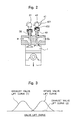
- Fig. 2 illustrates an intake valve 30, an intake valve-operating mechanism 31, an exhaust valve 40 and an exhaust valve-operating mechanism 41.
- An exhaust cam 42 constituting the exhaust valve-operating mechanism 41 includes a normal cam profile 421 for operating the exhaust valve 40 in the exhaust stroke, and an exhaust introduction cam profile 422 formed at a phase angle of about 90 degrees behind the cam profile 421 in the direction of rotation.
- the thus constituted exhaust cam 42 operates, as shown in Fig.
- the exhaust valve 40 in compliance with an exhaust valve lift curve (1) of the cam profile 421 and in compliance with an exhaust valve lift curve (2) of the exhaust introduction cam profile 422 which lasts for only a short period of time during the intake stroke (during the intake valve lift curve of the intake valve-operating mechanism 31).
- the exhaust introduction cam profile 422 formed on the exhaust cam 42 works as an exhaust gas introduction mechanism for introducing the exhaust gas into the cylinder during the intake stroke.
- the amount of lifting the exhaust valve 40 by the exhaust introduction cam profile 422 may be about 1 to 3 mm.
- an exhaust gas introduction mechanism 50 of the embodiment shown in Fig. 4 comprises an exhaust gas introduction valve 51 for opening the exhaust gas passage of the cylinder to the same cylinder during the intake stroke, and an electromagnetic solenoid 52 for operating the exhaust gas introduction valve 51.
- a control signal is sent, as a drive signal, from the control means 10 to the electromagnetic solenoid 52 causing the exhaust gas introduction valve 51 to be opened to drive during the intake stroke.
- an exhaust gas temperature region detecting means for detecting the exhaust gas temperature region of the diesel engine.
- the exhaust gas temperature region detecting means will now be described.
- the exhaust gas temperature of the engine is determined chiefly by the amount of fuel (load) supplied to the engine and by the engine rotational speed.
- the control means 10 in the device for purifying exhaust gas according to the illustrated embodiment has an internal memory (not shown) which stores a map of exhaust gas temperature regions using the engine rotational speed and the engine load as parameters as shown in Fig. 5, and detects in which region the exhaust gas temperature now lies from the engine rotational speed and the fuel injection amount (load).
- the region referred to here is a region of the temperature of the exhaust gas discharged from the cylinder.
- the boundary lines X, Y and Z shown in Fig. 5 are set by chiefly making reference to the experimental results related to the exhaust gas temperature of the engine and the active temperature region of the oxidizing catalyst 12 at the time of defining the map.
- the region X is a region where the temperature is higher than the active temperature region of the oxidizing catalyst 12
- the region Y is a region where the temperature lies in the active temperature region of the oxidizing catalyst 12
- the region Z is a region where the temperature is lower than the active temperature region of the oxidizing catalyst 12.
- boundary lines can be appropriately changed by the user depending on the operation characteristics of the diesel engine that is used and the characteristic properties of the catalyst that is used.
- the above temperature regions need not necessarily be limited to three regions, but may be divided into more regions or may be defined to be two regions.
- the control means 10 reads an engine rotational speed signal (Ne) and an accelerator opening degree signal (ACL) from the engine rotational speed sensor 15 and the accelerator sensor 16 (step S1), and makes reference to a map of fuel injection amounts (not shown) to determine an amount of fuel injection (step S2).
- the control means 10 detects the amount of fuel injection at this moment as a load Q for the engine.
- the control means 10 detects the present exhaust gas temperature region from the map of exhaust gas temperature regions shown in Fig. 5 based on the engine load and the engine rotational speed that has been detected as described above (step S3). After having thus detected the present exhaust gas temperature region, the control means 10 controls the intake air shutter 9 and the exhaust gas shutter 11 based on the present exhaust gas temperature region in compliance with a control map shown in Fig. 6.
- step S4 when the exhaust gas temperature region is in the active temperature region X of the oxidizing catalyst (step S4), the control means 10 fully opens the intake air shutter 9 and the exhaust gas shutter 11 according to the control map of Fig. 7 (step S5).
- the control means 10, then, executes the control operation for lowering the exhaust gas temperature (step S6).
- the control operation for lowering the exhaust gas temperature may be executed by, for example, a means for cooling the exhaust gas by using a cooling water or by separately providing a means for increasing the amount of the intake air, such as a mechanical supercharger.
- the control operation for lowering the exhaust gas temperature is not a principal constituent requirement of the present invention and hence, is not described here.
- the maps shown in Figs. 7(a) and 7(b) are the ones in which the region Z of the map used for the exhaust gas temperature region detecting means shown in Fig. 5 is further divided to set stepwise the respective operation for opening the intake and exhaust gas shutters.
- the word “opening degree 20%” means that the shutter is closed by 80% with respect to the fully opened position, and " opening degree 5%” means that it is closed by 95%.
- control flowchart After having performed the above control operation, the control flowchart returns back to the start.
- the exhaust gas valve 40 is opened during the intake stroke due to the action of the exhaust gas introduction cam profile 422 of the exhaust cam 42 that constitutes the exhaust gas introduction mechanism shown in Fig. 2, and the exhaust gas is introduced into the cylinder.
- the exhaust gas introduction mechanism 50 shown in Fig. 4 is provided, further, the electromagnetic solenoid 52 is driven during the intake stroke, and the exhaust gas introduction valve 51 is opened to introduce the exhaust gas into the cylinder.
- the exhaust gas pressure in the exhaust gas passage is in an elevated state with the consequence that the exhaust gas flowing back into the cylinder increases and it becomes possible to further raise the exhaust gas temperature.
- the control operation for squeezing the intake air shutter 9 the control operation for squeezing the exhaust gas shutter 11 and the operation of the exhaust gas introduction mechanism work as exhaust gas temperature-raising means for raising the exhaust gas temperature of the engine.
- the exhaust gas temperature region is detected based on the engine rotational speed and the load.
- the exhaust gas temperature region may be detected by using the exhaust gas temperature sensor 8 that is provided directly in the exhaust pipe 7 of the engine.
- the continuous regeneration type DPF has been described to be constituted by the oxidizing catalyst and the DPF as separate constituents, it needs not be pointed out that the present invention can similarly be applied even to a continuous regeneration type DPF in which a DPF directly carries a material that works as an oxidizing catalyst and is constituted as a unitary structure, to a continuous regeneration type DPF in which a DPF carries a NOx occluding/reducing catalyst, and to a continuous regeneration type DPF using a catalyst which effectively works in a limited temperature region only.
- the intake air shutter is operated to decrease the amount of the intake air and, at the same time, the exhaust gas passage is allowed to open into the cylinder during the intake stroke so that the exhaust gas flows back therein, making it possible to raise the exhaust gas temperature while suppressing the emission of HC without making the combustion worse.
- the effect can be further enhanced by operating the exhaust gas shutter. Accordingly, the device can be effectively applied particularly to the diesel engines mounted on the vehicles.
Landscapes
- Engineering & Computer Science (AREA)
- Mechanical Engineering (AREA)
- General Engineering & Computer Science (AREA)
- Chemical & Material Sciences (AREA)
- Combustion & Propulsion (AREA)
- Chemical Kinetics & Catalysis (AREA)
- Output Control And Ontrol Of Special Type Engine (AREA)
- Processes For Solid Components From Exhaust (AREA)
- Exhaust Gas After Treatment (AREA)
- Combined Controls Of Internal Combustion Engines (AREA)
- Electrical Control Of Air Or Fuel Supplied To Internal-Combustion Engine (AREA)
Abstract
A device for purifying exhaust gas of a diesel engine equipped with a continuous regeneration type diesel particulate filter arranged in the exhaust gas passage of the engine, which comprises an intake air shutter arranged in the intake air passage of the engine, an exhaust gas temperature region detecting means for detecting an exhaust gas temperature region of the engine, a control means for controlling to squeeze the opening degree of said intake air shutter when the exhaust gas temperature region of the engine, detected by said exhaust gas temperature region detecting means, is lower than a predetermined temperature region, and an exhaust valve-operating mechanism equipped with an exhaust gas introduction mechanism for opening the exhaust valve of the engine for a short period of time during the intake stroke. <IMAGE>
Description
The present invention relates to a device for purifying
exhaust gas of diesel engines for removing particulate
matters from the exhaust gas.
Regulations against the exhaust gases of diesel
engines mounted on vehicles are becoming stringent year after
year. In particular, it is becoming an urgent necessity to
decrease the particulate matters (hereinafter abbreviated
as PMs) which consists of carbon as a main component. As a
device for removing the PMs from the exhaust gas, there has
been known a diesel particulate filter (hereinafter
abbreviated as DPF), and a trend toward obligatorily
furnishing the vehicles mounting diesel engines with the DPF
becomes also serious.
The DPF with which the diesel engine mounted on the
vehicle is furnished must be regenerated by burning the PMs
that have been trapped because the PMs deposit on the DPF
due to repetitive operation of the engine. As a means for
regeneration of the DPF, there is a method to burn the PMs
by heating them with an electric heater, a burner or the like.
According to this method, a system that a plurality of DPFs
are arranged in parallel in the exhaust gas passage to
alternately conduct the trapping and the burning is
constituted. As another means for regenerating the DPF,
there has also been studied a so-called continuous
regeneration type DPF according to which an oxidizing
catalyst is disposed in the exhaust gas passage on the
upstream side of the DPF, NO in the exhaust gas is oxidized
into NO2 by the oxidizing catalyst, and the PMs are
continuously burned with NO2 while trapping the PMs as
disclosed in, for example, Japanese Patent No. 3012249.
Further, as another continuous regeneration type DPF, there
has been known a method in which a NOx occluding/reducing
catalyst is carried on the DPF and the PMs trapped are
continuously burned by using active oxygen that generates
when the NOx is occluded and reduced, as disclosed in Japanese
Patent No. 2600492. In both of these continuous regeneration
type DPFs, the PMs burn in a low temperature region of 250
to 400°C (which may shift up and down to some extent depending
on the material of the catalyst) without requiring any
particular heating means such as electric heater, burner or
the like, giving such an advantage that the devices as a whole
can be constructed simply and in a compact size.
Although it has been thus made possible to burn the
PMs in a range of a so-called active temperature region of
the catalyst, which can be easily accomplished by the exhaust
gas temperature of the engine as described above, there may
occur an operation condition that does not lie in this
temperature range depending on the operation conditions of
the engine. When the engine operates under a low-load
condition, in particular, there occurs a case where the
temperature of the exhaust gas does not rise and often fails
to reach 250°C, while during a high-load operation condition,
too, there is a case where the exhaust gas temperature often
exceeds the active temperature region and the PMs cannot
often be burned continuously.
In the above cases, when according to the operation
conditions, the temperature of the exhaust gas does not come
into the active temperature region of the catalyst and the
PMs trapped by the DPF do not burn, the PMs that do not burn
remain trapped by the DPF and accumulate thereon. Then, when
the engine operation condition changes and the temperature
of the exhaust gas comes into the active temperature region
of the catalyst, the PMs accumulated burn due to the action
described above. At this moment, if the accumulated PMs
start burning all at once, the temperature of combustion of
PMs becomes as high as 2000°C causing such problems as
melt-damage or the like to the filter body.
As described above, the continuous regeneration type
DPF continuously conducts the regeneration when the exhaust
gas is emitted while the PMs being trapped. Therefore, if
the DPF can be continuously regenerated at all times whenever
the engine is in operation, then, the temperature does not
reach so high a temperature as to cause melt-damage. Because
of this reason, it is important to maintain the temperature
of the exhaust gas to lie within the active temperature region
of the catalyst at all times.
By taking the above problems into consideration, the
present applicant has proposed Japanese Patent Applications
Nos. 2000-185897 and 2001-79266 in an attempt to maintain
the temperature of the exhaust gas in the active temperature
region of the catalyst.
The inventions of the above two applications were
proposed based on a knowledge that the temperature of the
exhaust gas is greatly affected by the amount of the air taken
in the cylinder of the engine, and it becomes high as the
excess air ratio (λ) to the fuel approaches to λ = 1 from
a large state and as the temperature of the air taken in the
cylinder becomes high (the temperature of the exhaust gas
becomes low if they are reversed).
That is, Japanese Patent Application No. 2000-185897
discloses that there are arranged an intake throttle valve
and a variable supercharger as air amount adjusting means,
and the temperature of the exhaust gas is controlled by
squeezing the intake throttle valve to decrease the amount
of the intake air and by controlling the variable
supercharger to increase the amount of the intake air.
Further, Japanese Patent Application No. 2001-79266
discloses that there are provided a so-called EGR passage
communicating the exhaust gas passage of the engine with the
intake air passage and an EGR valve for controlling the
passage area of the EGR passage, and the temperature of the
exhaust gas is controlled by controlling the flow rate of
the EGR gas refluxed from the exhaust gas reflux (EGR) passage
to the intake air passage side and by further controlling
the amount of the intake air by the intake air shutter in
the intake air passage and by the exhaust gas shutter in the
exhaust gas passage.
In a diesel engine, the amount of the intake air is
not usually controlled, and the excess air ratio (λ) becomes
large as the load is low, i.e., when the fuel is injected
in small amounts, and becomes λ = 10 or larger during the
idling operation. To bring the excess air ratio (λ) close
to 1, therefore, the amount of the intake air must be squeezed
to a considerable degree.
Meanwhile, as is well known, the diesel engine is a
combustion system based on the self-ignition by the
compression. That is, the i'ntake air is compressed based on
the compression ratio of the cylinder defined by a bore of
the cylinder and the stroke of the piston, the fuel is injected
into the cylinder in which the temperature has been raised
due to the compression and hence, the temperature of the fuel
itself is elevated, so that the fuel is self-ignited while
being vaporized. Therefore, the above method of decreasing
the amount of the intake air hinders the elevation of the
temperature of the intake air by the compression and produces
a condition where the self-ignition does not easily take
place. Namely, the above method arouses a new problem
inducing incomplete combustion in the cylinder and emitting
unburned HC (hydrocarbons).
Fig. 9 is a graph illustrating the effect produced as
a result of squeezing the intake air shutter, in which the
ordinate represents the exhaust gas temperature (°C) and HC
(x 100 ppm) and the abscissa represents the amount of the
intake air [kg/h]. The amount of the intake air is limited
by squeezing the intake air shutter stepwise. Solid lines
in the graph represent a change in the exhaust gas temperature
and the HC contained in the exhaust gas in the prior art,
that were measured by operating the intake air shutter only.
The data of Fig. 9 were measured by using a 4-cylinder 3-liter
diesel engine while driving it at a rotational speed (Ne)
of 1000 rpm, injecting the fuel at a rate (Q) of 10 mm3/st
and measuring the exhaust gas temperature at the outlet of
the exhaust manifold.
As will be obvious from Fig. 9, the exhaust gas
temperature is about 150°C when the intake air shutter is
not squeezed. The exhaust gas temperature gradually
increases as the intake air shutter is gradually squeezed.
However, the HC sharply increases as the amount of the intake
air approaches 80 kg/h. In a region where the amount of the
intake air lies between 70 and 80 kg/h, there takes place
an abnormal combustion permitting HC to be emitted in amounts
of exceeding 10,000 ppm. Then, the exhaust gas is spewed out
as white smoke from the exhaust pipe, the combustion is no
longer normally conducted, and the exhaust gas temperature
is not raised any more no matter how the intake air shutter
is squeezed. Therefore, the intake air shutter alone is not
enough for raising the exhaust gas temperature to a
sufficient degree.
The present invention has been accomplished in view
of the above-mentioned points, and its principal technical
assignment is to provide an improved device for purifying
exhaust gas of diesel engines mounting a continuous
regeneration type DPF by raising the exhaust gas temperature
even under operation conditions where the exhaust gas
temperature is low without deteriorating the fuel efficiency
and by promoting the continuous combustion of PMs in the
continuous regeneration type DPF, so that the PMs will not
be deposited on the DPF.
In order to solve the above-mentioned technical
assignment, according to the present invention, there is
provided a device for purifying exhaust gas of a diesel engine
equipped with a continuous regeneration type diesel
particulate filter arranged in the exhaust gas passage of
the engine, comprising:
In order to solve the above-mentioned technical
assignment according to the present invention, there is
further provided a device for purifying exhaust gas of a
diesel engine equipped with a continuous regeneration type
diesel particulate filter arranged in the exhaust gas passage
of the engine, comprising:
It is desired that when the exhaust gas temperature
region of the engine detected by the exhaust gas temperature
region detecting means is lower than a predetermined
temperature region, said control means controls stepwise so
as to decrease the opening degree of said intake air shutter
as the temperature region becomes low.
It is further desired that an exhaust gas shutter
arranged in the exhaust gas passage and for squeezing the
exhaust gas passage is provided, and the control means
controls so as to squeeze the opening degree of the exhaust
gas shutter when the exhaust gas temperature region detected
by the exhaust gas temperature region detecting means is in
a low temperature region. The opening degree of the exhaust
gas shutter is controlled stepwise to be decreased as the
temperature region becomes low.
Embodiments of the present invention will be described
below with reference to the drawings.
An engine body 2 constituted by a cylinder block, a
cylinder head and the like shown in Fig. 1 is provided with
an intake manifold 3 constituting part of the intake air
passage and with an exhaust manifold 4 constituting part of
the exhaust gas passage. An intake pipe 5 constituting part
of the intake air passage is connected to the intake manifold
3, and an air cleaner 6 is arranged in the uppermost stream
portion of the intake pipe 5 to clean the intake air. The
intake air cleaned through the air cleaner 6 passes through
the intake pipe 5 and is fed into the cylinder 1 as shown
in Fig. 2 through the intake manifold 3. An exhaust pipe 7
constituting part of the exhaust gas passage is connected
to the exhaust manifold 4, and the exhaust gas produced in
the cylinder 1 is discharged through the exhaust manifold
4 and the exhaust pipe 7. An intake air shutter 9 is arranged
in the intake pipe 5, and an exhaust gas shutter 11 is disposed
in the exhaust pipe 7. The intake air shutter 9 and the
exhaust gas shutter 11 are respectively provided with an air
actuator connected to an air tank that is not shown, and these
actuators are controlled by a control means 10.
In the exhaust pipe 7 of the illustrated diesel engine,
there are arranged a continuous regeneration type diesel
particulate filter (continuous regeneration type DPF) 12
comprising an oxidizing catalyst 121 and a DPF 122, as well
as a NOx catalyst 14 which are arranged in this order from
the upstream side. The oxidizing catalyst 121 used is the
one prepared by coating active alumina or the like on the
surface of a carrier formed of, for example, honeycomb-like
cordierite or a heat resistant steel to form a wash coat layer
and having a catalytically active component of a noble metal
such as platinum, palladium or rhodium carried on the coated
layer. This oxidizing catalyst 121 oxidizes NO in the
exhaust gas to form NO2 and oxidizes HC and CO in the exhaust
gas to form H2O and CO2. The DPF 122 may be, for example,
a honeycomb filter of the so-called wall-flow type in which
a number of porous cells are formed in parallel using
cordierite or silicon carbide, the inlets and outlets of the
cells being alternately closed, or a fiber-type filter in
which ceramic fibers are wound in many layers on a stainless
steel porous pipe, to trap the PMs contained in the exhaust
gas. The NOx catalyst 14 has the constitution and components
similar to those of the oxidizing catalyst 121, and reduces
NOx such as NO or the like contained in the exhaust gas into
N2 and H2O. Such continuous regeneration type DPF 12 works
to oxidize NO in the exhaust gas into NO2 by the oxidizing
catalyst 121 and to burn the trapped PMs by using NO2 that
flows into the DPF 122 arranged on the downstream side of
the oxidizing catalyst 121. Here, the PMs burn at a low
temperature which is not higher than 400°C without requiring
any special heating means such as an electric heater, a burner
or the like. Since while the PMs are continuously burned at
a low temperature, the PMs are newly trapped at the same time,
the device as a whole is constructed simply and in a compact
size advantageously.
The illustrated diesel engine comprises an engine
rotational speed (Ne) sensor 15 for detecting a rotational
speed of the engine, an accelerator sensor 16 for detecting
an accelerator pedal depression amount (accelerator opening
degree: ACL), an intake air temperature sensor 17 arranged
in the intake manifold 3 and for detecting the temperature
of the air taken in the cylinder, an exhaust gas temperature
sensor 8 arranged in the exhaust pipe 7 and for detecting
the exhaust gas temperature, and a control means 10 for
controlling the amount of fuel to be injected into the
cylinder by a fuel injection device (not shown) based on
detection signals from the above sensors. The control means
has a memory storing a map of fuel injection amounts (not
shown), in which the amounts of fuel injection are set using
the engine rotational speed and the accelerator opening
degree as parameters, and determines a basic amount of fuel
injection based on detection signals from the engine
rotational speed sensor 15 and from the accelerator sensor
16. Further, the control means 10 corrects the basic amount
of fuel injection based on a value detected by the intake
air temperature sensor 17 to determine a final amount of fuel
injection. Here, the final amount of fuel injection can be
corrected at any time by making reference to not only the
intake air temperature but also a variety of other parameters
(atmospheric pressure, smoke-limit injection amount, etc.).
Referring to Fig. 2, the diesel engine of this
embodiment has an exhaust gas introduction mechanism
(so-called exhaust two-step cam mechanism) that works to open
the exhaust gas passage of the cylinder to the cylinder during
the intake stroke. Fig. 2 illustrates an intake valve 30,
an intake valve-operating mechanism 31, an exhaust valve 40
and an exhaust valve-operating mechanism 41. An exhaust cam
42 constituting the exhaust valve-operating mechanism 41
includes a normal cam profile 421 for operating the exhaust
valve 40 in the exhaust stroke, and an exhaust introduction
cam profile 422 formed at a phase angle of about 90 degrees
behind the cam profile 421 in the direction of rotation. The
thus constituted exhaust cam 42 operates, as shown in Fig.
3, the exhaust valve 40 in compliance with an exhaust valve
lift curve (1) of the cam profile 421 and in compliance with
an exhaust valve lift curve (2) of the exhaust introduction
cam profile 422 which lasts for only a short period of time
during the intake stroke (during the intake valve lift curve
of the intake valve-operating mechanism 31). In the
embodiment shown in Fig. 2, therefore, the exhaust
introduction cam profile 422 formed on the exhaust cam 42
works as an exhaust gas introduction mechanism for
introducing the exhaust gas into the cylinder during the
intake stroke. The amount of lifting the exhaust valve 40
by the exhaust introduction cam profile 422 may be about 1
to 3 mm.
Next, another embodiment of the exhaust gas
introduction mechanism will be described with reference to
Fig. 4. In the embodiment shown in Fig. 4, the same members
as those of the embodiment of Fig. 2 are denoted by the same
reference numerals and hence, are not described here again
in detail.
In the embodiment shown in Fig. 4, the exhaust cam 42
constituting the exhaust valve-operating mechanism 41 has
the normal cam profile 421 only. An exhaust gas introduction
mechanism 50 of the embodiment shown in Fig. 4 comprises an
exhaust gas introduction valve 51 for opening the exhaust
gas passage of the cylinder to the same cylinder during the
intake stroke, and an electromagnetic solenoid 52 for
operating the exhaust gas introduction valve 51. When the
exhaust gas temperature region of the engine equipped with
the thus constituted exhaust gas introduction mechanism 50
is lower than a predetermined temperature region, a control
signal is sent, as a drive signal, from the control means
10 to the electromagnetic solenoid 52 causing the exhaust
gas introduction valve 51 to be opened to drive during the
intake stroke.
In the embodiment shown in Fig. 1, there is provided
with an exhaust gas temperature region detecting means for
detecting the exhaust gas temperature region of the diesel
engine. The exhaust gas temperature region detecting means
will now be described.
The exhaust gas temperature of the engine is determined
chiefly by the amount of fuel (load) supplied to the engine
and by the engine rotational speed. The control means 10 in
the device for purifying exhaust gas according to the
illustrated embodiment has an internal memory (not shown)
which stores a map of exhaust gas temperature regions using
the engine rotational speed and the engine load as parameters
as shown in Fig. 5, and detects in which region the exhaust
gas temperature now lies from the engine rotational speed
and the fuel injection amount (load). The region referred
to here is a region of the temperature of the exhaust gas
discharged from the cylinder.
The boundary lines X, Y and Z shown in Fig. 5 are set
by chiefly making reference to the experimental results
related to the exhaust gas temperature of the engine and the
active temperature region of the oxidizing catalyst 12 at
the time of defining the map. The region X is a region where
the temperature is higher than the active temperature region
of the oxidizing catalyst 12, the region Y is a region where
the temperature lies in the active temperature region of the
oxidizing catalyst 12, and the region Z is a region where
the temperature is lower than the active temperature region
of the oxidizing catalyst 12.
It needs not be pointed out that the boundary lines
can be appropriately changed by the user depending on the
operation characteristics of the diesel engine that is used
and the characteristic properties of the catalyst that is
used. The above temperature regions need not necessarily be
limited to three regions, but may be divided into more regions
or may be defined to be two regions.
Next, the operation of the device for purifying exhaust
gas according to the embodiment of Fig. 1 will be described
with reference to a flowchart illustrated in Fig. 8. At the
start (key on) of the engine, the intake air shutter has been
opened and, hence, consideration has been so given that the
starting performance is made not worse. When the engine
starts operating (after the start of the engine) , the control
operation of the flowchart starts feeding the fuel to the
engine from a fuel injection device that is not shown. The
control means 10 reads an engine rotational speed signal (Ne)
and an accelerator opening degree signal (ACL) from the
engine rotational speed sensor 15 and the accelerator sensor
16 (step S1), and makes reference to a map of fuel injection
amounts (not shown) to determine an amount of fuel injection
(step S2). The control means 10 detects the amount of fuel
injection at this moment as a load Q for the engine.
In the device for purifying exhaust gas according to
the embodiment of Fig. 1, when the engine load Q has been
detected as described above, the control means 10 detects
the present exhaust gas temperature region from the map of
exhaust gas temperature regions shown in Fig. 5 based on the
engine load and the engine rotational speed that has been
detected as described above (step S3). After having thus
detected the present exhaust gas temperature region, the
control means 10 controls the intake air shutter 9 and the
exhaust gas shutter 11 based on the present exhaust gas
temperature region in compliance with a control map shown
in Fig. 6.
First, when the exhaust gas temperature region is in
the active temperature region X of the oxidizing catalyst
(step S4), the control means 10 fully opens the intake air
shutter 9 and the exhaust gas shutter 11 according to the
control map of Fig. 7 (step S5). The control means 10, then,
executes the control operation for lowering the exhaust gas
temperature (step S6). The control operation for lowering
the exhaust gas temperature may be executed by, for example,
a means for cooling the exhaust gas by using a cooling water
or by separately providing a means for increasing the amount
of the intake air, such as a mechanical supercharger. The
control operation for lowering the exhaust gas temperature
is not a principal constituent requirement of the present
invention and hence, is not described here.
When the exhaust gas temperature region is other than
the region X at step S4, the control means 10 proceeds from
step S4 to step S7 to judge whether or not the exhaust gas
temperature region is the low temperature region Z. When it
is judged that the region is not the low temperature region
(but is the exhaust gas temperature region = Y), then, the
control means 10 proceeds to step S8 to fully open the intake
air shutter 9 and the exhaust gas shutter 11.
When it is judged at step S7 that the exhaust gas
temperature region is the low temperature region (exhaust
gas temperature region = Z), the control means 10 proceeds
to step S9 to operate the intake air shutter 9 thereby to
squeeze the shutter 9 based on the map of intake air shutter
opening degrees of Fig. 7(a). The control means 10, then,
proceeds to step S10 to operate the exhaust gas shutter 11
thereby to squeeze the shutter 11 based on the map of exhaust
gas shutter opening degrees of Fig. 7(b). The maps shown in
Figs. 7(a) and 7(b) are the ones in which the region Z of
the map used for the exhaust gas temperature region detecting
means shown in Fig. 5 is further divided to set stepwise the
respective operation for opening the intake and exhaust gas
shutters. The word "opening degree 20% " means that the
shutter is closed by 80% with respect to the fully opened
position, and " opening degree 5%" means that it is closed
by 95%.
After having performed the above control operation,
the control flowchart returns back to the start.
In the illustrated embodiment, the exhaust gas valve
40 is opened during the intake stroke due to the action of
the exhaust gas introduction cam profile 422 of the exhaust
cam 42 that constitutes the exhaust gas introduction
mechanism shown in Fig. 2, and the exhaust gas is introduced
into the cylinder. When the exhaust gas introduction
mechanism 50 shown in Fig. 4 is provided, further, the
electromagnetic solenoid 52 is driven during the intake
stroke, and the exhaust gas introduction valve 51 is opened
to introduce the exhaust gas into the cylinder. When the
exhaust gas temperature region is in the low-temperature
region (exhaust gas temperature region = Z) as described
above, the exhaust gas of a high temperature flowing through
the exhaust gas passage is caused to flow back into the
cylinder during the intake stroke. As a result, the exhaust
gas temperature is raised. Further, when the exhaust gas
shutter is controlled to close as described above, the
exhaust gas pressure in the exhaust gas passage is in an
elevated state with the consequence that the exhaust gas
flowing back into the cylinder increases and it becomes
possible to further raise the exhaust gas temperature. When
the exhaust gas temperature region is in the low-temperature
region (exhaust gas temperature region = Z), therefore, the
control operation for squeezing the intake air shutter 9,
the control operation for squeezing the exhaust gas shutter
11 and the operation of the exhaust gas introduction
mechanism work as exhaust gas temperature-raising means for
raising the exhaust gas temperature of the engine.
Effects in the concrete will be described with
reference to a graph of Fig. 9. When the intake air shutter
and the exhaust gas introduction mechanism that introduces
the exhaust gas during the intake stroke (exhaust two-step
cam mechanism) are operated (represented by lines coupled
with circle symbols), the amount of HC emission does not
almost increase even when the amount of the intake air is
squeezed down to about 40 kg/h and further, the exhaust gas
temperature exceeds 250°C, in contrast with the exhaust gas
temperature and amount of HC emission represented by solid
lines of the conventional cases where the intake air shutter
only is operated. And, when the amount of the intake air is
further squeezed, HC emission becomes worse. In this case,
however, when the exhaust gas shutter was operated (opening
degree of 20%, represented by a line coupled with square
symbols) , the exhaust gas temperature could be further raised
and the concentration of HC emission could be decreased.
Further, in case the amount of the intake air was to be further
squeezed down to 30 kg/h or smaller, when the exhaust gas
shutter was further squeezed (opening degree of 5%,
represented by a line coupled with triangle symbols), the
exhaust gas temperature exceeded 300°C and the HC emission
could be further decreased.
In the illustrated embodiments as described above, the
exhaust gas temperature region is detected based on the
engine rotational speed and the load. Not being limited
thereto only, however, the exhaust gas temperature region
may be detected by using the exhaust gas temperature sensor
8 that is provided directly in the exhaust pipe 7 of the engine.
Further, though in the illustrated embodiments, the
continuous regeneration type DPF has been described to be
constituted by the oxidizing catalyst and the DPF as separate
constituents, it needs not be pointed out that the present
invention can similarly be applied even to a continuous
regeneration type DPF in which a DPF directly carries a
material that works as an oxidizing catalyst and is
constituted as a unitary structure, to a continuous
regeneration type DPF in which a DPF carries a NOx
occluding/reducing catalyst, and to a continuous
regeneration type DPF using a catalyst which effectively
works in a limited temperature region only.
According to the device for purifying exhaust gas of
diesel engines of the present invention, when the exhaust
gas temperature is lower than the active temperature region
of the catalyst, the intake air shutter is operated to
decrease the amount of the intake air and, at the same time,
the exhaust gas passage is allowed to open into the cylinder
during the intake stroke so that the exhaust gas flows back
therein, making it possible to raise the exhaust gas
temperature while suppressing the emission of HC without
making the combustion worse. The effect can be further
enhanced by operating the exhaust gas shutter. Accordingly,
the device can be effectively applied particularly to the
diesel engines mounted on the vehicles.
Claims (8)
- A device for purifying exhaust gas of a diesel engine equipped with a continuous regeneration type diesel particulate filter arranged in the exhaust gas passage of the engine, comprising:an intake air shutter arranged in the intake air passage of the engine;an exhaust gas temperature region detecting means for detecting an exhaust gas temperature region of the engine;a control means for squeezing the opening degree of said intake air shutter when the exhaust gas temperature region of the engine, detected by said exhaust gas temperature region detecting means, is lower than a predetermined temperature region; andan exhaust valve-operating mechanism equipped with an exhaust gas introduction mechanism for opening the exhaust valve of the engine for a short period of time during the intake stroke.
- A device for purifying exhaust gas of a diesel engine according to claim 1, wherein when the exhaust gas temperature region of the engine, detected by said exhaust gas temperature region detecting means, is lower than a predetermined temperature region, said control means controls stepwise so as to decrease the opening degree of said intake air shutter as the temperature region becomes low.
- A device for purifying exhaust gas of a diesel engine according to claim 1, wherein an exhaust gas shutter arranged in the exhaust gas passage and for squeezing said exhaust gas passage is provided, and said control means controls so as to squeeze the opening degree of said exhaust gas shutter when the exhaust gas temperature region detected by said exhaust gas temperature region detecting means is in a low temperature region.
- A device for purifying exhaust gas of a diesel engine according to claim 3, wherein when the exhaust gas temperature region of the engine, detected by said exhaust gas temperature region detecting means, is lower than a predetermined temperature region, said control means controls stepwise so as to decrease the opening degree of said exhaust gas shutter as the temperature region becomes low.
- A device for purifying exhaust gas of a diesel engine equipped with a continuous regeneration type diesel particulate filter arranged in the exhaust gas passage of the engine, comprising:an intake air shutter arranged in the intake air passage of the engine;an exhaust gas introduction mechanism for opening the exhaust gas passage to the cylinder during the intake stroke;an exhaust gas temperature region detecting means for detecting the exhaust gas temperature region of the engine; anda control means for squeezing the opening degree of the intake air shutter and for operating said exhaust gas introduction mechanism when the exhaust gas temperature region'of the engine, detected by said exhaust gas temperature region detecting means, is lower than a predetermined temperature region.
- A device for purifying exhaust gas of a diesel engine according to claim 5, wherein when the exhaust gas temperature region of the engine, detected by said exhaust gas temperature region detecting means, is lower than a predetermined temperature region, said control means controls stepwise so as to decrease the opening degree of said intake air shutter as the temperature region becomes low.
- A device for purifying exhaust gas of a diesel engine according to claim 5, wherein an exhaust gas shutter arranged in the exhaust passage and for squeezing said exhaust gas passage is provided, and said control means controls so as to squeeze the opening degree of said exhaust gas shutter when the exhaust gas temperature detected by said exhaust gas temperature region detecting means is in a low temperature region.
- A device for purifying exhaust gas of a diesel engine according to claim 7, wherein when the exhaust gas temperature region of the engine, detected by said exhaust gas temperature region detecting means, is lower than a predetermined temperature region, said control means controls stepwise so as to decrease the opening degree of said exhaust gas shutter as the temperature region becomes low.
Applications Claiming Priority (3)
| Application Number | Priority Date | Filing Date | Title |
|---|---|---|---|
| JP2001155895 | 2001-05-24 | ||
| JP2001155895A JP2002349239A (en) | 2001-05-24 | 2001-05-24 | Diesel engine exhaust purification system |
| PCT/JP2002/004974 WO2002095197A1 (en) | 2001-05-24 | 2002-05-23 | Diesel engine exhaust purifying device |
Publications (2)
| Publication Number | Publication Date |
|---|---|
| EP1389674A1 true EP1389674A1 (en) | 2004-02-18 |
| EP1389674A4 EP1389674A4 (en) | 2011-04-27 |
Family
ID=18999998
Family Applications (1)
| Application Number | Title | Priority Date | Filing Date |
|---|---|---|---|
| EP02730692A Withdrawn EP1389674A4 (en) | 2001-05-24 | 2002-05-23 | Diesel engine exhaust purifying device |
Country Status (4)
| Country | Link |
|---|---|
| US (1) | US6823661B2 (en) |
| EP (1) | EP1389674A4 (en) |
| JP (1) | JP2002349239A (en) |
| WO (1) | WO2002095197A1 (en) |
Cited By (3)
| Publication number | Priority date | Publication date | Assignee | Title |
|---|---|---|---|---|
| EP1612392A2 (en) | 2004-06-30 | 2006-01-04 | DaimlerChrysler AG | Method for operating a combustion engine |
| KR101133290B1 (en) * | 2007-09-25 | 2012-04-04 | 도요타지도샤가부시키가이샤 | Control apparatus and control method for internal combustion engine |
| CN105888860A (en) * | 2015-02-17 | 2016-08-24 | 丰田自动车株式会社 | Control Apparatus For Internal Combustion Engine |
Families Citing this family (18)
| Publication number | Priority date | Publication date | Assignee | Title |
|---|---|---|---|---|
| JP2004176663A (en) * | 2002-11-28 | 2004-06-24 | Honda Motor Co Ltd | Exhaust purification device for internal combustion engine |
| DE10352498A1 (en) * | 2003-11-11 | 2005-06-09 | Daimlerchrysler Ag | Method for operating an internal combustion engine |
| JP3992016B2 (en) * | 2004-05-17 | 2007-10-17 | トヨタ自動車株式会社 | Control device for premixed compression self-ignition internal combustion engine |
| US7461504B2 (en) * | 2004-12-21 | 2008-12-09 | Detroit Diesel Corporation | Method and system for controlling temperatures of exhaust gases emitted from internal combustion engine to facilitate regeneration of a particulate filter |
| US8091347B2 (en) * | 2005-02-28 | 2012-01-10 | Yanmar Co., Ltd. | Exhaust gas purification apparatus, internal combustion engine comprising the same, and particulate filter restoring method |
| DE102005036438A1 (en) * | 2005-08-03 | 2007-02-08 | Robert Bosch Gmbh | Method and device for operating an internal combustion engine |
| DE102005036440A1 (en) * | 2005-08-03 | 2007-02-08 | Robert Bosch Gmbh | Method and device for operating an internal combustion engine |
| JP4573303B2 (en) * | 2006-01-10 | 2010-11-04 | Udトラックス株式会社 | Pumping loss reduction device and reduction method |
| US8322129B2 (en) * | 2006-02-16 | 2012-12-04 | Cummins, Inc. | Method for controlling turbine outlet temperatures in a diesel engine |
| FR2897654A1 (en) * | 2006-02-20 | 2007-08-24 | Renault Sas | METHOD AND DEVICE FOR REGENERATING THE PARTICLE FILTER OF AN INTERNAL COMBUSTION ENGINE. |
| US20090173062A1 (en) * | 2008-01-04 | 2009-07-09 | Caterpillar Inc. | Engine system having valve actuated filter regeneration |
| US20100050874A1 (en) * | 2008-08-29 | 2010-03-04 | Walter Cullen Lucas | Exhaust after treatment system and method |
| JP5464059B2 (en) * | 2010-06-04 | 2014-04-09 | マツダ株式会社 | ENGINE CONTROL METHOD AND CONTROL DEVICE |
| JP5986736B2 (en) * | 2011-11-16 | 2016-09-06 | 三菱重工業株式会社 | Exhaust gas purification system for internal combustion engine |
| JP5862292B2 (en) * | 2011-12-28 | 2016-02-16 | マツダ株式会社 | Diesel engine control device |
| CN103809048A (en) * | 2012-11-06 | 2014-05-21 | 上海航天设备制造总厂 | Electro-pneumatic valve tester |
| CN104806365A (en) * | 2015-03-31 | 2015-07-29 | 凯龙高科技股份有限公司 | Air inlet throttle regeneration temperature control method of DPF diesel engine granule filtering system |
| JP7879768B2 (en) | 2022-09-05 | 2026-06-24 | 株式会社小松製作所 | Exhaust gas purification device, exhaust gas purification method, and control device |
Family Cites Families (12)
| Publication number | Priority date | Publication date | Assignee | Title |
|---|---|---|---|---|
| JPH0710014Y2 (en) * | 1990-02-22 | 1995-03-08 | マツダ株式会社 | Exhaust gas purification device for a diesel engine |
| JP3024780B2 (en) * | 1990-07-25 | 2000-03-21 | 日産ディーゼル工業株式会社 | Diesel engine exhaust purification system |
| JPH06129231A (en) * | 1992-10-20 | 1994-05-10 | Kanesaka Gijutsu Kenkyusho:Kk | Particulate. How to handle particulates in the trap |
| JP3677954B2 (en) * | 1997-07-23 | 2005-08-03 | 日産自動車株式会社 | Control device for internal combustion engine |
| AT2410U1 (en) * | 1997-09-16 | 1998-10-27 | Avl List Gmbh | METHOD FOR REGENERATING A PARTICLE FILTER |
| JP3331935B2 (en) * | 1997-12-04 | 2002-10-07 | トヨタ自動車株式会社 | Compression ignition type internal combustion engine |
| DE19926138A1 (en) * | 1999-06-09 | 2000-12-14 | Volkswagen Ag | Purifying IC engine exhaust gas comprises taking measures to increase exhaust gas temperature with introduction of event which can be canceled after combustion |
| DE19948156A1 (en) * | 1999-10-07 | 2001-04-12 | Volkswagen Ag | Process for purifying internal combustion engine exhaust gases comprises determining the nitrogen dioxide and carbon amounts in the gas, and increasing and/or decreasing the amounts to lie in a determined nitrogen dioxide/carbon ratio |
| JP3562415B2 (en) * | 1999-12-24 | 2004-09-08 | トヨタ自動車株式会社 | Internal combustion engine with variable valve mechanism |
| US6519933B2 (en) * | 2000-03-21 | 2003-02-18 | Toyota Jidosha Kabushiki Kaisha | Internal combustion engine having variable valve control system and NOx catalyst |
| US6439210B1 (en) * | 2000-07-12 | 2002-08-27 | Caterpillar Inc. | Exhaust gas reprocessing/recirculation with variable valve timing |
| US6394051B1 (en) * | 2000-09-01 | 2002-05-28 | Ford Global Technologies, Inc. | Spark ignition engine with negative valve-overlap |
-
2001
- 2001-05-24 JP JP2001155895A patent/JP2002349239A/en active Pending
-
2002
- 2002-05-23 EP EP02730692A patent/EP1389674A4/en not_active Withdrawn
- 2002-05-23 WO PCT/JP2002/004974 patent/WO2002095197A1/en not_active Ceased
- 2002-05-23 US US10/333,634 patent/US6823661B2/en not_active Expired - Lifetime
Cited By (6)
| Publication number | Priority date | Publication date | Assignee | Title |
|---|---|---|---|---|
| EP1612392A2 (en) | 2004-06-30 | 2006-01-04 | DaimlerChrysler AG | Method for operating a combustion engine |
| US7225610B2 (en) | 2004-06-30 | 2007-06-05 | Daimlerchrysler Ag | Process for operating a combustion engine |
| DE102004031502B4 (en) * | 2004-06-30 | 2013-12-05 | Daimler Ag | Method for operating an internal combustion engine |
| KR101133290B1 (en) * | 2007-09-25 | 2012-04-04 | 도요타지도샤가부시키가이샤 | Control apparatus and control method for internal combustion engine |
| CN105888860A (en) * | 2015-02-17 | 2016-08-24 | 丰田自动车株式会社 | Control Apparatus For Internal Combustion Engine |
| CN105888860B (en) * | 2015-02-17 | 2019-03-08 | 丰田自动车株式会社 | Control devices for internal combustion engines |
Also Published As
| Publication number | Publication date |
|---|---|
| WO2002095197A1 (en) | 2002-11-28 |
| JP2002349239A (en) | 2002-12-04 |
| EP1389674A4 (en) | 2011-04-27 |
| US20030172644A1 (en) | 2003-09-18 |
| US6823661B2 (en) | 2004-11-30 |
Similar Documents
| Publication | Publication Date | Title |
|---|---|---|
| US6823661B2 (en) | Diesel engine exhaust purifying device | |
| US6742331B2 (en) | Device for purifying exhaust gas of diesel engines | |
| US6865882B2 (en) | Device for purifying exhaust gas of diesel engines | |
| US7370474B2 (en) | Exhaust gas purifying equipment for a diesel engine | |
| CN100572768C (en) | Emission control system | |
| EP1350932B1 (en) | Exhaust emission control system of a diesel engine and method therefore | |
| US5850735A (en) | Method for purifying exhaust gas of an internal combustion engine | |
| EP1400664B1 (en) | Exhaust gas purifying method and exhaust gas purifying system | |
| JP2002276405A (en) | Diesel engine exhaust purification system | |
| EP1840348A1 (en) | EGR System for Engine | |
| JP3896998B2 (en) | Exhaust gas purification device for internal combustion engine | |
| JP4012043B2 (en) | Particulate filter regeneration method | |
| CN100472038C (en) | Internal combustion engine exhaust emission control device | |
| JP2004028030A (en) | Exhaust gas purification device for internal combustion engine | |
| EP1867846B1 (en) | DPF regeneration system of internal combustion engine | |
| JP2004257267A (en) | Exhaust gas purification system for internal combustion engine | |
| JP2011220260A (en) | Engine control device | |
| JP7163585B2 (en) | engine controller | |
| JP4489504B2 (en) | Diesel engine exhaust purification system | |
| JP2003155915A (en) | Exhaust gas purification device | |
| JP4735505B2 (en) | Surge prevention control device and surge prevention control method for turbocharged engine | |
| JP2002004838A (en) | Diesel engine exhaust purification system | |
| JPH03233122A (en) | Exhaust treatment device of internal combustion engine |
Legal Events
| Date | Code | Title | Description |
|---|---|---|---|
| PUAI | Public reference made under article 153(3) epc to a published international application that has entered the european phase |
Free format text: ORIGINAL CODE: 0009012 |
|
| 17P | Request for examination filed |
Effective date: 20031112 |
|
| AK | Designated contracting states |
Kind code of ref document: A1 Designated state(s): AT BE CH CY DE DK ES FI FR GB GR IE IT LI LU MC NL PT SE TR |
|
| A4 | Supplementary search report drawn up and despatched |
Effective date: 20110325 |
|
| 17Q | First examination report despatched |
Effective date: 20110701 |
|
| STAA | Information on the status of an ep patent application or granted ep patent |
Free format text: STATUS: THE APPLICATION IS DEEMED TO BE WITHDRAWN |
|
| 18D | Application deemed to be withdrawn |
Effective date: 20111115 |