EP1389550A2 - Latch for an automotive vehicle having a convertible roof - Google Patents
Latch for an automotive vehicle having a convertible roof Download PDFInfo
- Publication number
- EP1389550A2 EP1389550A2 EP03255026A EP03255026A EP1389550A2 EP 1389550 A2 EP1389550 A2 EP 1389550A2 EP 03255026 A EP03255026 A EP 03255026A EP 03255026 A EP03255026 A EP 03255026A EP 1389550 A2 EP1389550 A2 EP 1389550A2
- Authority
- EP
- European Patent Office
- Prior art keywords
- roof
- latch
- operably
- link
- actuator
- Prior art date
- Legal status (The legal status is an assumption and is not a legal conclusion. Google has not performed a legal analysis and makes no representation as to the accuracy of the status listed.)
- Granted
Links
Images


Classifications
-
- B—PERFORMING OPERATIONS; TRANSPORTING
- B60—VEHICLES IN GENERAL
- B60J—WINDOWS, WINDSCREENS, NON-FIXED ROOFS, DOORS, OR SIMILAR DEVICES FOR VEHICLES; REMOVABLE EXTERNAL PROTECTIVE COVERINGS SPECIALLY ADAPTED FOR VEHICLES
- B60J7/00—Non-fixed roofs; Roofs with movable panels, e.g. rotary sunroofs
- B60J7/20—Vehicle storage compartments for roof parts or for collapsible flexible tops
- B60J7/202—Vehicle storage compartments for roof parts or for collapsible flexible tops being characterised by moveable cover parts for closing the gap between boot lid and rearmost seats
-
- B—PERFORMING OPERATIONS; TRANSPORTING
- B60—VEHICLES IN GENERAL
- B60J—WINDOWS, WINDSCREENS, NON-FIXED ROOFS, DOORS, OR SIMILAR DEVICES FOR VEHICLES; REMOVABLE EXTERNAL PROTECTIVE COVERINGS SPECIALLY ADAPTED FOR VEHICLES
- B60J7/00—Non-fixed roofs; Roofs with movable panels, e.g. rotary sunroofs
- B60J7/08—Non-fixed roofs; Roofs with movable panels, e.g. rotary sunroofs of non-sliding type, i.e. movable or removable roofs or panels, e.g. let-down tops or roofs capable of being easily detached or of assuming a collapsed or inoperative position
- B60J7/12—Non-fixed roofs; Roofs with movable panels, e.g. rotary sunroofs of non-sliding type, i.e. movable or removable roofs or panels, e.g. let-down tops or roofs capable of being easily detached or of assuming a collapsed or inoperative position foldable; Tensioning mechanisms therefor, e.g. struts
- B60J7/14—Non-fixed roofs; Roofs with movable panels, e.g. rotary sunroofs of non-sliding type, i.e. movable or removable roofs or panels, e.g. let-down tops or roofs capable of being easily detached or of assuming a collapsed or inoperative position foldable; Tensioning mechanisms therefor, e.g. struts with a plurality of rigid plate-like elements or rigid non plate-like elements, e.g. with non-slidable, but pivotable or foldable movement
- B60J7/143—Non-fixed roofs; Roofs with movable panels, e.g. rotary sunroofs of non-sliding type, i.e. movable or removable roofs or panels, e.g. let-down tops or roofs capable of being easily detached or of assuming a collapsed or inoperative position foldable; Tensioning mechanisms therefor, e.g. struts with a plurality of rigid plate-like elements or rigid non plate-like elements, e.g. with non-slidable, but pivotable or foldable movement for covering the passenger compartment
- B60J7/146—Non-fixed roofs; Roofs with movable panels, e.g. rotary sunroofs of non-sliding type, i.e. movable or removable roofs or panels, e.g. let-down tops or roofs capable of being easily detached or of assuming a collapsed or inoperative position foldable; Tensioning mechanisms therefor, e.g. struts with a plurality of rigid plate-like elements or rigid non plate-like elements, e.g. with non-slidable, but pivotable or foldable movement for covering the passenger compartment all elements being folded in same orientation and stacked fashion
-
- B—PERFORMING OPERATIONS; TRANSPORTING
- B60—VEHICLES IN GENERAL
- B60J—WINDOWS, WINDSCREENS, NON-FIXED ROOFS, DOORS, OR SIMILAR DEVICES FOR VEHICLES; REMOVABLE EXTERNAL PROTECTIVE COVERINGS SPECIALLY ADAPTED FOR VEHICLES
- B60J7/00—Non-fixed roofs; Roofs with movable panels, e.g. rotary sunroofs
- B60J7/08—Non-fixed roofs; Roofs with movable panels, e.g. rotary sunroofs of non-sliding type, i.e. movable or removable roofs or panels, e.g. let-down tops or roofs capable of being easily detached or of assuming a collapsed or inoperative position
- B60J7/12—Non-fixed roofs; Roofs with movable panels, e.g. rotary sunroofs of non-sliding type, i.e. movable or removable roofs or panels, e.g. let-down tops or roofs capable of being easily detached or of assuming a collapsed or inoperative position foldable; Tensioning mechanisms therefor, e.g. struts
- B60J7/14—Non-fixed roofs; Roofs with movable panels, e.g. rotary sunroofs of non-sliding type, i.e. movable or removable roofs or panels, e.g. let-down tops or roofs capable of being easily detached or of assuming a collapsed or inoperative position foldable; Tensioning mechanisms therefor, e.g. struts with a plurality of rigid plate-like elements or rigid non plate-like elements, e.g. with non-slidable, but pivotable or foldable movement
- B60J7/143—Non-fixed roofs; Roofs with movable panels, e.g. rotary sunroofs of non-sliding type, i.e. movable or removable roofs or panels, e.g. let-down tops or roofs capable of being easily detached or of assuming a collapsed or inoperative position foldable; Tensioning mechanisms therefor, e.g. struts with a plurality of rigid plate-like elements or rigid non plate-like elements, e.g. with non-slidable, but pivotable or foldable movement for covering the passenger compartment
- B60J7/148—Non-fixed roofs; Roofs with movable panels, e.g. rotary sunroofs of non-sliding type, i.e. movable or removable roofs or panels, e.g. let-down tops or roofs capable of being easily detached or of assuming a collapsed or inoperative position foldable; Tensioning mechanisms therefor, e.g. struts with a plurality of rigid plate-like elements or rigid non plate-like elements, e.g. with non-slidable, but pivotable or foldable movement for covering the passenger compartment at least one element being stored in vertical fashion
-
- B—PERFORMING OPERATIONS; TRANSPORTING
- B60—VEHICLES IN GENERAL
- B60J—WINDOWS, WINDSCREENS, NON-FIXED ROOFS, DOORS, OR SIMILAR DEVICES FOR VEHICLES; REMOVABLE EXTERNAL PROTECTIVE COVERINGS SPECIALLY ADAPTED FOR VEHICLES
- B60J7/00—Non-fixed roofs; Roofs with movable panels, e.g. rotary sunroofs
- B60J7/185—Locking arrangements
- B60J7/19—Locking arrangements for rigid panels
-
- Y—GENERAL TAGGING OF NEW TECHNOLOGICAL DEVELOPMENTS; GENERAL TAGGING OF CROSS-SECTIONAL TECHNOLOGIES SPANNING OVER SEVERAL SECTIONS OF THE IPC; TECHNICAL SUBJECTS COVERED BY FORMER USPC CROSS-REFERENCE ART COLLECTIONS [XRACs] AND DIGESTS
- Y10—TECHNICAL SUBJECTS COVERED BY FORMER USPC
- Y10S—TECHNICAL SUBJECTS COVERED BY FORMER USPC CROSS-REFERENCE ART COLLECTIONS [XRACs] AND DIGESTS
- Y10S292/00—Closure fasteners
- Y10S292/05—Automobile top latches
Landscapes
- Engineering & Computer Science (AREA)
- Mechanical Engineering (AREA)
- Vehicle Step Arrangements And Article Storage (AREA)
- Body Structure For Vehicles (AREA)
- Lock And Its Accessories (AREA)
Abstract
Description
- This invention relates generally to automotive roof systems and more particularly to a latch for an automotive vehicle having a convertible roof.
- Rigid hard-top convertible roofs have been used on a variety of automotive vehicles. Some of these conventional convertible hard-top roofs are stored in a generally vertical orientation and some are stored in a predominantly horizontal orientation. Furthermore, some of these conventional hard-top roofs fold in a clamshelling manner while others are collapsible in an overlapping manner. Examples of traditional hard-top convertible roofs are disclosed in the following patents: U.S. Patent No. 6,347,828 entitled "Actuation Mechanism for a Two Piece Retractable Hard-Top Roof for an Automobile" which issued to Rapin et al. on February 19, 2002; U.S. Patent No. 6,318,793 entitled "Two Piece Retractable Hard-Top Roof for an Automobile" which issued to Rapin et al. on November 20, 2001; U.S. Patent No. 5,979,970 entitled "Roof Assembly for a Convertible Vehicle" which issued to Rothe et al. on November 9, 1999; U.S. Patent No. 5,785,375 entitled "Retractable Hard-Top for an Automotive Vehicle" which issued to Alexander et al. on July 28, 1998; U.S. Patent No. 5,769,483 entitled "Convertible Motor Vehicle Roof' which issued to Danzl et al. on June 23, 1998; U.S. Patent No. 5,743,587 entitled "Apparatus for Use in an Automotive Vehicle having a Convertible Roof System" which issued to Alexander et al. on April 28, 1998; and EPO Patent Publication No. 1 092 580 A1 which was published on April 18, 2001. The U.S. patents are incorporated by reference herein.
- Various tonneau cover latches are disclosed in U.S. Patent Nos.: 5,678,881 entitled "Apparatus and Method for Securing a Convertible Roof to an Automotive Vehicle" which issued to Tokarz on October 21, 1997; and 5,267,769 entitled "Manually Operable Folding Top for Vehicles using Automatic-Ejection Snap-Action Closures" which issued to Bonne et al. on December 7, 1993; both of which are incorporated by reference herein. While the Tokarz latches are significant improvements in the industry, many known devices may not necessarily be well suited for use in extremely difficult to package areas along the quarter panel of a vehicle. Furthermore, the tonneau cover and convertible roof may be locked into lowered positions if the electrical power is not working with most, if not all, prior automatically powered latching devices.
- In accordance with one aspect of the present invention, a latching system for an automotive vehicle having a convertible roof is provided. In another aspect of the present invention, front and/or rear convertible roof sections are rigid, hard-top roofs. A further aspect of the present invention provides that the outside surfaces of retractable roofs have a generally vertical orientation when in their open and retracted positions. In yet another aspect of the present invention, a latch secures a generally rigid tonneau cover. A latch is extremely thin in cross-car size for packaging adjacent a quarter panel of a vehicle, in still another aspect of the present invention. A further aspect of the present invention provides a manual override for an automatically powered latch. Another aspect of the present invention uses a rigid tonneau cover, a tonneau cover linkage mechanism, a movable closeout panel, and a cable drive, which serve to cover a roof storage space and the roof storage space does not obstruct a trunk or storage bed area of a vehicle. In a further aspect of the present invention, a method of using a latch is also provided.
- The preferred latching system of the present invention is advantageous over conventional systems in that it minimizes the stored roof packaging area by tightly collapsing one roof section relative to the other. The preferred convertible roof system is also advantageous since it can be retracted with minimal, if any, intrusion in the passenger compartment area of the vehicle while also storing the roof forward of a user accessible storage area, such as a trunk or pickup truck bed. The preferred latch of the present invention is advantageous over prior devices by having an extremely thin cross-car size which is packaged in a very tight quarter panel area. Moreover, another significant advantage is the ability to manually override the automatic actuator in order to release or latch the tonneau cover in the event of a power failure. Additional advantages and features will become apparent from the following description and appended claims, taken in conjunction with the accompanying drawings, in which:
- Figure 1 is a fragmentary, perspective view, as observed from the rear left corner of the vehicle, showing the preferred embodiment of a latch and convertible roof system of the present invention disposed in a fully closed and raised position;
- Figure 2 is a fragmentary and perspective view, like that of Figure 1, showing the preferred embodiment system disposed in a partially retracted position;
- Figure 3 is a fragmentary and perspective view, like that of Figure 1, showing the preferred embodiment system disposed in a fully open and retracted position;
- Figure 4 is a side diagrammatic view showing the preferred embodiment system, disposed in the partially retracted position;
- Figure 5 is a side diagrammatic view showing the preferred embodiment system, disposed in the fully retracted position;
- Figure 6 is a centerline cross sectional view, taken along line 6-6 of Figure 3, showing the preferred embodiment system;
- Figure 7 is a front perspective view showing a tonneau cover mechanism employed in the preferred embodiment system, disposed in a partially open position;
- Figure 8 is an enlarged, side elevational view showing the tonneau cover mechanism employed in the preferred embodiment system, disposed in the partially open position;
- Figure 9 is a front perspective view showing the tonneau cover mechanism employed in the preferred embodiment system, disposed in the partially open position and a closeout panel shown in a retracted position;
- Figure 10 is an exploded perspective view showing the tonneau cover mechanism employed in the preferred embodiment system;
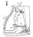
- Figure 11 is a side elevational view showing a latch assembly employed in the preferred embodiment system, disposed in an unlatched position;
- Figure 12 is a side elevational view, opposite that of Figure 11, showing the latch assembly employed in the preferred embodiment system, disposed in the unlatched position;
- Figure 13 is a top elevational view showing the latch assembly employed in the preferred embodiment system;
- Figure 14 is a side elevational view, opposite that of Figure 11, showing the latch assembly employed in the preferred embodiment system, disposed in a latched position;
- Figure 15 is a side elevational view, opposite that of Figure 11, showing the latch assembly employed in the preferred embodiment system, disposed in the manually overridden, unlatched position;
- Figure 16 is a side elevational view, opposite that of Figure 11, showing the latch assembly employed in the preferred embodiment system, disposed in the manually overridden, latched position
- Figure 17 is a diagrammatic view showing a first tonneau cover switching mechanism employed in an alternate embodiment system;
- Figure 18 is a diagrammatic view showing a second tonneau cover switching mechanism employed in the preferred embodiment system;
- Figure 19 is a front perspective view showing an actuator used with the tonneau cover and closeout panel employed in the preferred embodiment system;
- Figure 20 is a side elevational view showing manual override handles of the latch assembly employed in the preferred embodiment;
- Figure 21 is a perspective view showing a stationary bracket and a cable employed in an alternate embodiment;
- Figure 22 is a side elevational view, like that of Figure 12, showing the latch assembly employed in the alternate embodiment system, disposed in an unlatched position;
- Figure 23 is a side elevational view, like that of Figure 14, showing the latch assembly employed in the alternate embodiment system, disposed in a latched position;
- Figure 24 is a side elevational view, like that of Figure 15, showing the latch assembly employed in the alternate embodiment system, disposed in a manually overridden, unlatched position;
- Figure 25 is a side elevational view, like that of Figure 16, showing the latch assembly employed in the alternate embodiment system, disposed in a manually overridden, latch position; and
- Figure 26 is a front perspective view, like Figure 19, showing a cable used with the tonneau cover and closeout panel employed in the alternate embodiment system.
-
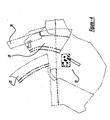
- Referring to Figures 1-6, a
convertible roof system 21 is part of an automotive vehicle and includes a hard-top front roof 23, a hard-toprear roof 25, atop stack mechanism 27 operable to move the roofs, arigid tonneau cover 29, atonneau cover mechanism 31 and atonneau latching system 32.Roofs passenger compartment 33, as shown in Figure 1, to fully retracted and open positions, as shown in Figures 3, 5 and 6, whereinroofs compartment 35.Roof storage compartment 35 is located between a metal, seat back panel orbulkhead 35a and a metalrear panel 36. Bulkhead 35a separatesroof storage compartment 35 frompassenger compartment 33 andrear panel 36 separatesroof storage compartment 35 from an externally accessible storage area for miscellaneous articles such as a trunk orpickup truck bed 37. A rigid, glass back window orbacklite 39 is secured torear roof 25 whilefront roof 23 is disengagably attached to afront header panel 41 by latches. Weatherstrips or seals are also employed around the peripheral edges ofroofs Roofs Roofs -
Top stack mechanism 27 is in mirrored symmetry in both outboard sides of the vehicle and will only be described for the left-hand side with reference to Figures 3, 6 and 21.Top stack mechanism 27 includes alinkage assembly 51 and ahydraulic actuator 55.Linkage assembly 51 is preferably constructed in accordance with German patent application serial number 101 39 354.7 entitled "Cabriolet-Fahrzeug" (Vehicle) which was filed on August 17, 2001, which is incorporated by reference herein.Roofs linkage assembly 51. -
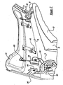
Tonneau cover mechanism 31 andtonneau cover 29 are best shown in Figures 7-10 and 19; only one side will be discussed since the other is in mirrored symmetry.Tonneau cover mechanism 31 includes alinkage assembly 103 having a pair ofarcuate gooseneck links straight link 109 and a secondstraight link 111. Proximal ends ofgooseneck links Straight links pivot 113. A hydraulic actuator 115 (see Figure 10) is coupled to and drivesgooseneck link 105. Accordingly, whenhydraulic actuator 115 is energized,tonneau cover mechanism 31 will causetonneau cover 29 to rearwardly pivot from the closed position of Figure 1 to the open position of Figure 4. This allowsroofs roof storage area 35.Tonneau cover 29 will be automatically returned to its closed position in order to cover and externally hide the stowed roofs. - A rigid flipper door or
closeout panel 141 is attached to a front section oftonneau cover 29 by a pair ofhinges 143. For eachhinge 143, a first plate is secured to a bottom surface oftonneau cover 29 and a second plate is secured to a bottom surface ofcloseout panel 141. If necessary, the plates are coupled at a pivot pin with a torsion spring 489 (best observed in Figure 19) biasing the plates into a co-planar extended orientation (as shown in Figures 3, 7 and 19). An aesthetic trim panel 144 (see Figure 10) covers a portion of eachtonneau cover mechanism 31 and a latch trim panel covers a portion of each latch assembly. Preferably, a pair of automatic, hydraulicfluid actuators 629 each have a first, linearlyextendable rod end 633 coupled to a bracket mounted tocloseout panel 141. Afluid cylinder end 631 of eachfluid actuator 629 is mounted to a tonneau cover bracket. Thus, actuation offluid actuators 629 rotatecloseout panel 141 relative totonneau cover 29.Adjustable bumpers 635 assist in locatingtonneau cover 29 in its closed position. In an alternate embodiment, shown in Figure 21 and 26, a first end of acable actuator 145, which slides within a protective sheath, is connected to and operably drives a corresponding lever/bracket 146 mounted tocloseout panel 141. The opposite end of eachcable 145 is secured to a fixedcable bracket 147 stationarily mounted to amain bracket 149 supportingroof linkage assembly 51, which in turn, is fastened tobulkhead 35a. - Referring to Figures 11-13, the preferred embodiment of latching
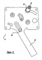
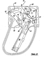
system 32 includes a stampedsteel plate 201, upon which is fixed a linearly extendablehydraulic actuator 203, a latchinglinkage assembly 205 and a lostmotion device 207. Latchinglinkage assembly 205 includes an arcuately shapedfirst link 209, an elongatedsecond link 211 and an offset angledthird link 213. Afirst pivot 215 ofarcuate link 209 is linearly slid within an elongated and diagonally orientedslot 221 disposed inplate 201 upon automatic actuation ofactuator 203 which causes extension of a piston rod coupled to pivot 215.Second link 211 is rotatably coupled toarcuate link 209 at a floatingpivot 223. Thus, automatic actuator-driven movement ofarcuate link 209 causes the coupledlink 211 to rotate about a fixedpivot 225 such that afollower pin 227 coupled to link 211 is linearly slid from an unlatched position shown in Figures 11 and 12 to a latched position as shown in Figure 14. A catch orroller 229 is journaled aboutfollower pin 227 andfollower pin 227 is operably slid within an arcuate surface defining aslot 231 inplate 201.Roller 229 engages within a tapered bifurcated opening of astriker 241 downwardly and forwardly projecting from a lower surface of tonneau cover 29 (see Figures 7, 8 and 18), whentonneau cover 29 is in its fully closed and covering position as shown in Figure 1 and whenlatch assembly 32 is in its fully latched position as shown in Figures 11 and 14. When a microprocessor based controller 407 (see Figure 18) automatically causes retraction of the piston rod into the hydraulic cylinder ofactuator 203, the links will reverse operation and causeroller 229 to rotate from its latching position to an unlatching position thereby releasingstriker 241. - A manual override feature is provided within latching
system 32 to allow a vehicle operator to manually latch or unlatchroller 229 withstriker 241 even when electrical or hydraulic power is not present, such as could happen during vehicle servicing or due to battery failure. Such an override feature is achieved through ametallic disk 251 of lostmotion device 207 which is rotatable about a fixedpivot 253. An internal, straight,camming slot 255 is disposed withindisk 251 and has a pair of abuttingsurfaces cam follower pin 261 projecting fromlink 213 is allowed to freely move in a lost-motion manner withinslot 255 during normal automatic operation oflatch assembly 32. Flexible andelongated cables 271 are attached to disk by spaced apartfasteners 273; operator accessible handles 275 (see Figure 20) are located within the automotive vehicle and are attached to an opposite end of eachcable 271 such that manual pulling of one handle causes manually actuated rotation ofdisk 251 in that direction while manual pulling of the other handle causes reverse rotation ofdisk 251. Thus, manually actuated rotation ofdisk 251 serves to back drive the linkages through contact of the respective abuttingsurface 259 againstpin 261 oflink 213; this causes link 213 then upwardly and rotatably pulls or pushespivot 215 attached toarcuate link 209 for coincidentally drivinglink 211 androller 229. The manually overridden unlatching position can be viewed in Figure 15 while the manually overridden unlatching position can be observed in Figure 16. - It is noteworthy that
linkage assembly 32 is extremely thin in its cross-car package.Plate 201 is secured to a quarter inner panel of the vehicle body outboard of the roof storage compartment with all of the linkages and actuators disposed between the quarter inner panel and the outer quarter panel skin of the vehicle. Essentially,only roller 229, a portion of the hydraulic lines and a portion of the manual override cables/handles are exposed on the in-board side ofplate 201 thereby reducing the accessibility of components which might otherwise interfere with retraction or extension of the convertible roofs. - Reference should now be made to Figures 12 and 18 wherein a
Hall effect magnet 410 is mounted on an outboard face of eachstriker 241. AHall effect switch 409 is affixed to eachplate 201 which operably senses the location ofmagnet 410; ifmagnet 410 is sensed as being in the tonneau striker closed position, then switch 409 sends a signal tomicroprocessor 407 which causescylinder 203 to engageroller 229 withstriker 241. - Referring to Figures 22-25, an alternate embodiment of a latching system 32' includes a stamped steel plate 201', upon which is fixed a linearly extendable hydraulic actuator 203', a latching linkage assembly 205' and a lost motion device 207'. Latching linkage assembly 205' includes an arcuately shaped first link 209', an elongated second link 211' and a hook-like third link 213'. A first pivot 215' of arcuate link 209' is linearly slid within an elongated and diagonally oriented slot 221' disposed in plate 201' upon automatic actuation of actuator 203' which causes extension of a piston rod coupled to pivot 215'. Second link 211' is rotatably coupled to arcuate link 209' at a floating pivot 223'. Thus, automatic actuator-driven movement of arcuate link 209' causes the coupled link 211' to rotate about a fixed pivot 225' such that a follower pin 227' coupled to link 211' is linearly slid from an unlatched position shown in Figure 22 to a latched position as shown in Figure 23. A roller 229' is journaled about follower pin 227' and follower pin 227' is operably slid within an arcuate surface defining a slot 231' in plate 201'. Roller 229' has a somewhat inwardly tapered, H cross sectional shape which operably engages within a tapered bifurcated opening of a
striker 241 downwardly and forwardly projecting from a lower surface of tonneau cover 29 (see Figures 7, 8 and 18), whentonneau cover 29 is in its fully closed and covering position as shown in Figure 1 and when latch assembly 32' is in its fully latched position as shown in Figure 23. When a microprocessor based controller automatically causes retraction of the piston rod into the hydraulic cylinder of actuator 203', the links will reverse operation and cause roller 229' to rotate from its latching position to an unlatching position thereby releasingstriker 241. - A manual override feature is provided within latching system 32' to allow a vehicle operator to manually latch or unlatch roller 229' with
striker 241 even when electrical or hydraulic power is not present, such as could happen during vehicle servicing or due to battery failure. Such an override feature is achieved through a metallic disk 251' of lost motion device 207' which is rotatable about a fixed pivot 253'. A depressed camming slot 255' is disposed within disk 251' and has a pair of abutting surfaces 257' and 259'. A bent, cam following finger 261' of hook-like link 213' is allowed to freely move in a lost-motion manner within slot 255' during normal automatic operation of latch assembly 32'. Flexible and elongated cables 271' are attached to disk by spaced apart fasteners 273'; operator accessible handles 275 (see Figure 20) are located within the automotive vehicle and are attached to an opposite end of each cable 271' such that manual pulling of one handle causes manually actuated rotation of disk 251' in that direction while manual pulling of the other handle causes reverse rotation of disk 251'. Thus, manually actuated rotation of disk 251' serves to back drive the linkages through contact of the respective abutting surface 259' against finger 261' of link 213'; this causes a follower pin 291' attached to link 213' to slide within a camming slot 293' such that link 213' then upwardly and rotatably pulls or pushes an intermediate pivot 295' attached to arcuate link 209' for coincidentally driving link 211' and roller 229'. The manually overridden unlatching position can be viewed in Figure 24 while the manually overridden unlatching position can be observed in Figure 25. - All of the top stack mechanism actuators and tonneau cover actuators may be controlled in accordance with the control system disclosed in U.S. Patent No. 5,451,849 entitled "Motorized Self-Correcting Automatic Convertible Top" which issued to Porter et al. on September 19, 1995, which is incorporated by reference herein, or through hall effect sensors coupled to a microprocessor controller. For example, in the alternate embodiment, Figure 17 illustrates a
locator pin 401 downwardly extending from a bracket attached to an underside of tonneau cover 29 (see Figures 7 and 8). When fully closed,locator pin 401 enters within a body-mounted receptacle 403 and pushes a tongue of amicro switch 405 coupled to a microprocessor-basedcontroller 407. Suchmicro switch 405 actuation serves to then actuate a hydraulic pump which causes extension of hydraulic actuator 203 (see Figure 12). Referring now to Figure 18, whenroller 229 is fully engaged withinstriker 241, roller depresses a tongue of amicro switch 409 which transmits a signal tocontroller 407 to cause deactivation ofhydraulic actuator 203. - While various embodiments of the latching and convertible roof system have been disclosed, it should be appreciated that variations may be made to the present invention. For example, the presently disclosed latch can be used in other areas of the vehicle such as for the front header-to-one bow attachment or as a roof downstack latch, although certain advantages of the present invention may not be achieved. Furthermore, the present latch can be used to secure a hook or striker extending from a trunk lid which may be used to cover a retracted roof. Also, the hard-top roofs can be covered with vinyl, fabric or painted, or can include transparent glass panels. The present invention latch can alternately be used with a soft top roof. Moreover, electric motor actuators can be used in place of one or more of the disclosed hydraulic actuators. It should also be appreciated that the trunk compartment can be in front of the passenger compartment for a mid or rear engine vehicle. While certain materials and shapes have been disclosed, it should be appreciated that various other shapes and materials can be employed. It is intended by the following claims to cover these and any other departures from the disclosed embodiments which fall within the true spirit of this invention.
Claims (20)
- A convertible roof system comprising:a substantially rigid member movable from a closed position to an open position, the substantially rigid member being at least one of:(a) a hard-top roof member movable from a closed position to an open position; or(b) a tonneau cover member movable to cover a convertible roof when the convertible roof is in its open position; anda latch having an automatic actuator and a manual override actuator, the latch operably securing at least one of the members.
- The system of Claim 1 further comprising:a stationary bracket remotely located from the tonneau cover member;a tonneau linkage mechanism operably moving the tonneau cover member between its positions;an automatic tonneau actuator coupled to and operably driving the tonneau linkage mechanism;an auxiliary closeout panel movably coupled to the tonneau cover member; andan elongated cable connecting the auxiliary closeout panel to the stationary bracket.
- The system of Claim 1 or Claim 2 wherein the manual override actuator further comprises:a lost motion coupling; andat least one manually operable handle coupled to the lost motion coupling.
- The system of Claim 3 further comprising:a latching linkage assembly selectively engagable with the lost motion coupling;the automatic actuator operably driving the latching linkage assembly when in an energized automatic mode of operation;a catch movably coupled to the latching linkage assembly; andat least one cable connecting the handle to the lost motion coupling, the handle being remotely displaced from the lost motion coupling and the catch.
- The system of Claim 1 further comprising:a stationary vehicle body having a convertible roof storage compartment operably receiving the roof member when the roof,member is in the open position;the latch further including a latching linkage assembly, operably driven by the automatic actuator, and a movable catch coupled to the latching linkage assembly;the automatic actuator and latching linkage assembly being located outboard of the roof storage compartment; andthe catch being located within the roof storage compartment.
- The system of Claim 5 further comprising a striker projecting from the tonneau cover member, the catch operably disengaging from the striker in response to movement of either the automatic actuator or the manual override actuator.
- The system of any one of the preceding claims, further comprising a magnetic sensor operably indicating a position of the tonneau cover member and the sensor operably sending a signal which causes a changed condition of the automatic actuator.
- The system of any one of the preceding claims, wherein the roof member includes a front hard-top panel and a rear hard-top panel, both of which are stored in a nested and substantially vertical orientation below the tonneau cover member when the roof member is located in its open position and the tonneau cover member is located in a closed position.
- The system of Claim 1 further comprising:a linkage assembly coupled to the tonneau cover member, the linkage assembly including at least an arcuate gooseneck link; andan automatic tonneau actuator operably driving the linkage assembly;the linkage assembly operably pivoting the tonneau cover member between a closed and substantially horizontal position, and an open and substantially vertical position.
- An automotive vehicle latch assembly comprising:a plate;an automatic actuator mounted to the plate;a first link pivotably coupled to the automatic actuator;a second link pivotably coupled to the first link;a third link coupled to the first link and being spaced from the second link; anda catch coupled to the second link, the second link operably moving the catch from a first position to a second position, the catch being located on an opposite face of the plate from the first and second links.
- The assembly of Claim 10 further comprising a lost-motion mechanism movably coupled to the plate and selectively engaging at least one of the links.
- The assembly of Claim 11 further comprising at least one manually actuable handle coupled to the lost motion mechanism by at least one elongated member, the handle operably rotating the lost-motion mechanism in order to manually move the links and the catch.
- The assembly of any one of Claims 10 to 12 further comprising a rotary member having a camming surface, a cam follower projecting from the second link operably engaging the camming surface.
- The assembly of any one of Claims 10 to 13 wherein the catch is a roller and the automatic actuator is fluid-powered.
- The assembly of any one of claims 10 to 14 further comprising an electrical switch operably transmitting a signal indicative of a position of a convertible roof compartment cover which causes the automatic actuator to move the catch.
- A method of operating a convertible roof system including a retractable roof, a latch, and a roof storage compartment cover having a striker, the method comprising:(a) automatically retracting the roof from a raised position to a stowed position;(b) automatically moving the compartment cover from an uncovering position to a roof covering position;(c) energizing an automatic actuator;(d) rotating a first link of the latch;(e) sliding a first member of the latch along an arcuate path to simultaneously move an interface structure of the latch;(f) engaging the interface structure of the latch with the striker; andg) selectively engaging a lost motion mechanism in the latch.
- The method of Claim 16 further comprising rotating the interface structure of the latch along a substantially fore-and-aft and vertical plane to engage the striker.
- The method of Claim 16 or Claim 17 further comprising manually moving a handle to rotate the lost-motion mechanism which moves the interface structure of the latch.
- The method of Claim 16 further comprising applying fluid pressure within the automatic actuator in order to move the links and the interface structure of the latch.
- The method of any one of Claims 16 to 19 further comprising automatically rotating the compartment cover from the uncovering position to the roof covering position, and storing the retracted roof entirely outside of a miscellaneous storage compartment.
Applications Claiming Priority (4)
| Application Number | Priority Date | Filing Date | Title |
|---|---|---|---|
| US40371602P | 2002-08-15 | 2002-08-15 | |
| US403716P | 2002-08-15 | ||
| US10/638,948 US7140666B2 (en) | 2002-08-15 | 2003-08-11 | Latch for an automobile vehicle having a convertible roof |
| US638948 | 2003-08-11 |
Publications (4)
| Publication Number | Publication Date |
|---|---|
| EP1389550A2 true EP1389550A2 (en) | 2004-02-18 |
| EP1389550A3 EP1389550A3 (en) | 2005-08-03 |
| EP1389550B1 EP1389550B1 (en) | 2008-06-18 |
| EP1389550B8 EP1389550B8 (en) | 2008-08-13 |
Family
ID=30773142
Family Applications (1)
| Application Number | Title | Priority Date | Filing Date |
|---|---|---|---|
| EP03255026A Expired - Lifetime EP1389550B8 (en) | 2002-08-15 | 2003-08-13 | Latch for an automotive vehicle having a convertible roof |
Country Status (4)
| Country | Link |
|---|---|
| US (1) | US7140666B2 (en) |
| EP (1) | EP1389550B8 (en) |
| AT (1) | ATE398539T1 (en) |
| DE (1) | DE60321629D1 (en) |
Cited By (3)
| Publication number | Priority date | Publication date | Assignee | Title |
|---|---|---|---|---|
| EP1852290A2 (en) * | 2006-05-03 | 2007-11-07 | Magna Car Top Systems GmbH | Moveable roof part in the roof of a vehicle |
| WO2008003277A1 (en) * | 2006-07-04 | 2008-01-10 | Wilhelm Karmann Gmbh | Sensor system for monitoring a convertible soft top |
| EP1897736A2 (en) * | 2006-09-08 | 2008-03-12 | Dr.Ing. h.c.F. Porsche Aktiengesellschaft | Assembly for a soft top container cover on a motor vehicle |
Families Citing this family (13)
| Publication number | Priority date | Publication date | Assignee | Title |
|---|---|---|---|---|
| CA2539402C (en) * | 2003-11-04 | 2011-12-20 | Intier Automotive Closures Inc. | Panoramic retractable top |
| DE102004020639C5 (en) * | 2004-04-27 | 2007-12-06 | Wilhelm Karmann Gmbh | Convertible device for a vehicle |
| US7347482B2 (en) * | 2004-08-31 | 2008-03-25 | Specialty Vehicle Acquisition Corp. | Tonneau cover system |
| JP4790465B2 (en) * | 2006-03-28 | 2011-10-12 | ベバスト ジャパン株式会社 | Retractable roof and vehicle equipped with the same |
| DE102006016853B4 (en) * | 2006-04-07 | 2008-01-03 | Magna Car Top Systems Gmbh | Adjustable vehicle roof |
| DE102006039014A1 (en) * | 2006-08-19 | 2008-02-28 | Magna Car Top Systems Gmbh | Multi-part roof for a motor vehicle |
| DE102006042203A1 (en) * | 2006-09-08 | 2008-03-27 | Dr.Ing.H.C. F. Porsche Ag | vehicle roof |
| DE102007032728A1 (en) * | 2007-07-13 | 2009-01-15 | Dr. Ing. H.C. F. Porsche Aktiengesellschaft | Dämmanordnung |
| JP5177536B2 (en) * | 2008-09-25 | 2013-04-03 | アイシン精機株式会社 | Open roof opening and closing device |
| EP2196343A1 (en) * | 2008-12-12 | 2010-06-16 | Mazda Motor Corporation | Roof opening structure for a vehicle |
| US10377271B2 (en) | 2016-06-29 | 2019-08-13 | Bae Industries, Inc. | Release latch incorporated into a rear wall of a vehicle such as a truck cab |
| DE102016120562B4 (en) * | 2016-10-27 | 2023-02-09 | Webasto SE | Cabriolet vehicle with cover device for rod exit opening |
| US11724668B1 (en) | 2022-01-10 | 2023-08-15 | Toyota Motor Engineering & Manufacturing North America, Inc. | Integrated alarm systems for truck bed covers |
Citations (10)
| Publication number | Priority date | Publication date | Assignee | Title |
|---|---|---|---|---|
| US5267769A (en) | 1991-07-16 | 1993-12-07 | Mercedes-Benz Ag | Manually operable folding top for vehicles using automatic-ejection snap-action closures |
| US5678881A (en) | 1992-09-04 | 1997-10-21 | Asc Incorporated | Apparatus and method for securing a convertible roof to an automotive vehicle |
| US5743587A (en) | 1993-12-29 | 1998-04-28 | Asc Incorporated | Apparatus for use in an automotive vehicle having a convertible roof system |
| US5769483A (en) | 1994-09-30 | 1998-06-23 | Webasto Karosseriesysteme Gmbh | Convertible motor vehicle roof |
| US5785375A (en) | 1993-12-29 | 1998-07-28 | Asc Incorporated | Retractable hard-top for an automotive vehicle |
| US5979970A (en) | 1996-11-23 | 1999-11-09 | Wilhelm Karmann Gmbh | Roof assembly for a convertible vehicle |
| EP1092580A1 (en) | 1999-10-12 | 2001-04-18 | Dura Convertible Systems GmbH | Retractable hardtop for motor vehicle and motor vehicle provided with such hardtop |
| US6318793B1 (en) | 2000-12-29 | 2001-11-20 | General Motors Corporation | Two piece retractable hard-top roof for an automobile |
| US6347828B1 (en) | 2000-12-29 | 2002-02-19 | General Motors Corporation | Actuation mechanism for a two piece retractable hard-top roof for an automobile |
| DE10139354A1 (en) | 2001-08-17 | 2003-03-13 | Karmann Gmbh W | Convertible car |
Family Cites Families (25)
| Publication number | Priority date | Publication date | Assignee | Title |
|---|---|---|---|---|
| JPS6390432A (en) | 1986-10-02 | 1988-04-21 | Mazda Motor Corp | Structure of upper car body of automobile |
| CA1318793C (en) * | 1987-09-23 | 1993-06-08 | Michael Walter Malesko | Trunk lid lock with remote release |
| US4979384A (en) | 1987-09-23 | 1990-12-25 | Lectron Products, Inc. | Trunk lid lock with remote release |
| US5186516A (en) | 1987-09-24 | 1993-02-16 | Asc Incorporated | Power latch system |
| US5225747A (en) | 1992-01-06 | 1993-07-06 | Asc Incorporated | Single-button actuated self-correcting automatic convertible top |
| US5445326A (en) | 1993-12-21 | 1995-08-29 | Ferro; Joseph | Emergency trunk interior release latch |
| US5711559A (en) | 1994-04-15 | 1998-01-27 | Davis; Roland L. | Automobile trunk lid release |
| US5755467A (en) | 1995-01-31 | 1998-05-26 | Asc Incorporated | Latching and switch operating system for a convertible roof |
| US5772274A (en) * | 1995-01-31 | 1998-06-30 | Asc Incorporated | Motorized drive system for a convertible roof of an automotive vehicle |
| US5620226A (en) | 1995-12-07 | 1997-04-15 | Dura Convertible Systems, Inc. | Simplified automated top operator |
| DE29620492U1 (en) | 1996-11-25 | 1998-03-26 | Karmann Gmbh W | Cabriolet vehicle |
| FR2777240B1 (en) | 1998-04-09 | 2000-06-09 | France Design | REAR TRUNK FOR DISCOVERABLE VEHICLE WITH FOLDABLE ROOF, COMPRISING A REAR TRUNK AND A REAR BEACH |
| FR2778610B1 (en) | 1998-05-12 | 2000-08-04 | France Design | FOLDABLE ROOF IN THREE ELEMENTS FOR DISCOVERABLE VEHICLE |
| US5998948A (en) * | 1998-05-29 | 1999-12-07 | Acs Incorporated | Convertible roof actuation mechanism |
| US6390529B1 (en) | 1999-03-24 | 2002-05-21 | Donnelly Corporation | Safety release for a trunk of a vehicle |
| EP1038710B1 (en) | 1999-03-26 | 2003-05-21 | CTS Fahrzeug-Dachsysteme GmbH | Articulated tonneau cover |
| NL1012064C2 (en) | 1999-05-14 | 2000-11-20 | Applied Power Inc | Cover cap assembly with hydraulic actuator. |
| US6290281B1 (en) | 1999-05-26 | 2001-09-18 | Asc Incorporated | Power latch for an automotive vehicle convertible roof system |
| FI110418B (en) | 2000-05-05 | 2003-01-31 | Valmet Automotive Oy | Convertible |
| US6254165B1 (en) | 2000-08-16 | 2001-07-03 | Cts Fahrzeug Dachsysteme Gmbh | Tonneau cover and decklid linkage and drive system |
| US6508502B2 (en) | 2001-02-08 | 2003-01-21 | Asc Incorporated | Convertible roof and tonneau cover system |
| US6581989B2 (en) | 2001-05-08 | 2003-06-24 | Frank Markisello | Safety release device for closure latches, release latch and storage compartment utilizing safety release device, and method of installing safety release device |
| US6659534B2 (en) | 2001-08-15 | 2003-12-09 | Asc Incorporated | Hard-top convertible roof system |
| US6497447B1 (en) | 2001-08-15 | 2002-12-24 | Asc Incorporated | Convertible hard top for vehicles |
| DE10153137B4 (en) | 2001-10-27 | 2005-03-10 | Karmann Gmbh W | Cabriolet vehicle with a below a level of a cover part storable roof |
-
2003
- 2003-08-11 US US10/638,948 patent/US7140666B2/en not_active Expired - Fee Related
- 2003-08-13 AT AT03255026T patent/ATE398539T1/en not_active IP Right Cessation
- 2003-08-13 DE DE60321629T patent/DE60321629D1/en not_active Expired - Lifetime
- 2003-08-13 EP EP03255026A patent/EP1389550B8/en not_active Expired - Lifetime
Patent Citations (10)
| Publication number | Priority date | Publication date | Assignee | Title |
|---|---|---|---|---|
| US5267769A (en) | 1991-07-16 | 1993-12-07 | Mercedes-Benz Ag | Manually operable folding top for vehicles using automatic-ejection snap-action closures |
| US5678881A (en) | 1992-09-04 | 1997-10-21 | Asc Incorporated | Apparatus and method for securing a convertible roof to an automotive vehicle |
| US5743587A (en) | 1993-12-29 | 1998-04-28 | Asc Incorporated | Apparatus for use in an automotive vehicle having a convertible roof system |
| US5785375A (en) | 1993-12-29 | 1998-07-28 | Asc Incorporated | Retractable hard-top for an automotive vehicle |
| US5769483A (en) | 1994-09-30 | 1998-06-23 | Webasto Karosseriesysteme Gmbh | Convertible motor vehicle roof |
| US5979970A (en) | 1996-11-23 | 1999-11-09 | Wilhelm Karmann Gmbh | Roof assembly for a convertible vehicle |
| EP1092580A1 (en) | 1999-10-12 | 2001-04-18 | Dura Convertible Systems GmbH | Retractable hardtop for motor vehicle and motor vehicle provided with such hardtop |
| US6318793B1 (en) | 2000-12-29 | 2001-11-20 | General Motors Corporation | Two piece retractable hard-top roof for an automobile |
| US6347828B1 (en) | 2000-12-29 | 2002-02-19 | General Motors Corporation | Actuation mechanism for a two piece retractable hard-top roof for an automobile |
| DE10139354A1 (en) | 2001-08-17 | 2003-03-13 | Karmann Gmbh W | Convertible car |
Cited By (5)
| Publication number | Priority date | Publication date | Assignee | Title |
|---|---|---|---|---|
| EP1852290A2 (en) * | 2006-05-03 | 2007-11-07 | Magna Car Top Systems GmbH | Moveable roof part in the roof of a vehicle |
| EP1852290A3 (en) * | 2006-05-03 | 2009-12-09 | Magna Car Top Systems GmbH | Moveable roof part in the roof of a vehicle |
| WO2008003277A1 (en) * | 2006-07-04 | 2008-01-10 | Wilhelm Karmann Gmbh | Sensor system for monitoring a convertible soft top |
| EP1897736A2 (en) * | 2006-09-08 | 2008-03-12 | Dr.Ing. h.c.F. Porsche Aktiengesellschaft | Assembly for a soft top container cover on a motor vehicle |
| EP1897736A3 (en) * | 2006-09-08 | 2010-03-31 | Dr. Ing. h.c. F. Porsche AG | Assembly for a soft top container cover on a motor vehicle |
Also Published As
| Publication number | Publication date |
|---|---|
| US20040119317A1 (en) | 2004-06-24 |
| EP1389550B8 (en) | 2008-08-13 |
| DE60321629D1 (en) | 2008-07-31 |
| EP1389550A3 (en) | 2005-08-03 |
| US7140666B2 (en) | 2006-11-28 |
| EP1389550B1 (en) | 2008-06-18 |
| ATE398539T1 (en) | 2008-07-15 |
Similar Documents
| Publication | Publication Date | Title |
|---|---|---|
| US6659534B2 (en) | Hard-top convertible roof system | |
| US7140666B2 (en) | Latch for an automobile vehicle having a convertible roof | |
| US5998948A (en) | Convertible roof actuation mechanism | |
| US5624149A (en) | Apparatus and method for securing a convertible roof to an automotive vehicle | |
| US6695386B1 (en) | Vehicle retractable hardtop roof | |
| US7341303B2 (en) | Joint locking device for a convertible roof system | |
| US5903119A (en) | Convertible roof actuation mechanism | |
| US5743587A (en) | Apparatus for use in an automotive vehicle having a convertible roof system | |
| US7690716B2 (en) | Convertible roof | |
| EP1182072B1 (en) | Tonneau cover and decklid and drive system | |
| EP1574376A2 (en) | Convertible hardtop roof | |
| US6497447B1 (en) | Convertible hard top for vehicles | |
| WO2002096685A2 (en) | Automotive vehicle with open air roof system | |
| US20040222658A1 (en) | Retractable roof structural system | |
| US6837535B2 (en) | Convertible roof system | |
| US6568495B1 (en) | Automotive vehicle hood system | |
| US7014247B2 (en) | Hardtop convertible | |
| US7032951B2 (en) | Convertible vehicle top stack mechanism | |
| EP1389549A2 (en) | Convertible roof latch | |
| US6820917B2 (en) | Vehicle convertible roof | |
| US6692061B1 (en) | Vehicle convertible roof | |
| US7708332B2 (en) | Convertible roof system |
Legal Events
| Date | Code | Title | Description |
|---|---|---|---|
| PUAI | Public reference made under article 153(3) epc to a published international application that has entered the european phase |
Free format text: ORIGINAL CODE: 0009012 |
|
| AK | Designated contracting states |
Kind code of ref document: A2 Designated state(s): AT BE BG CH CY CZ DE DK EE ES FI FR GB GR HU IE IT LI LU MC NL PT RO SE SI SK TR |
|
| AX | Request for extension of the european patent |
Extension state: AL LT LV MK |
|
| PUAL | Search report despatched |
Free format text: ORIGINAL CODE: 0009013 |
|
| AK | Designated contracting states |
Kind code of ref document: A3 Designated state(s): AT BE BG CH CY CZ DE DK EE ES FI FR GB GR HU IE IT LI LU MC NL PT RO SE SI SK TR |
|
| AX | Request for extension of the european patent |
Extension state: AL LT LV MK |
|
| RIC1 | Information provided on ipc code assigned before grant |
Ipc: 7B 60J 7/20 A Ipc: 7B 60J 7/185 B |
|
| 17P | Request for examination filed |
Effective date: 20050916 |
|
| AKX | Designation fees paid |
Designated state(s): AT BE BG CH CY CZ DE DK EE ES FI FR GB GR HU IE IT LI LU MC NL PT RO SE SI SK TR |
|
| 17Q | First examination report despatched |
Effective date: 20051115 |
|
| RAP1 | Party data changed (applicant data changed or rights of an application transferred) |
Owner name: SSR ROOFING SYSTEM, LLC |
|
| RAP1 | Party data changed (applicant data changed or rights of an application transferred) |
Owner name: ASC INCORPORATED Owner name: WILHELM KARMANN GMBH |
|
| RAP1 | Party data changed (applicant data changed or rights of an application transferred) |
Owner name: WILHELM KARMANN GMBH Owner name: SPECIALTY VEHICLE ACQUISITION CORP. |
|
| GRAP | Despatch of communication of intention to grant a patent |
Free format text: ORIGINAL CODE: EPIDOSNIGR1 |
|
| GRAS | Grant fee paid |
Free format text: ORIGINAL CODE: EPIDOSNIGR3 |
|
| GRAA | (expected) grant |
Free format text: ORIGINAL CODE: 0009210 |
|
| AK | Designated contracting states |
Kind code of ref document: B1 Designated state(s): AT BE BG CH CY CZ DE DK EE ES FI FR GB GR HU IE IT LI LU MC NL PT RO SE SI SK TR |
|
| REG | Reference to a national code |
Ref country code: GB Ref legal event code: FG4D |
|
| RAP2 | Party data changed (patent owner data changed or rights of a patent transferred) |
Owner name: WILHELM KARMANN GMBH |
|
| REF | Corresponds to: |
Ref document number: 60321629 Country of ref document: DE Date of ref document: 20080731 Kind code of ref document: P |
|
| REG | Reference to a national code |
Ref country code: CH Ref legal event code: EP |
|
| REG | Reference to a national code |
Ref country code: IE Ref legal event code: FG4D |
|
| NLT2 | Nl: modifications (of names), taken from the european patent patent bulletin |
Owner name: WILHELM KARMANN GMBH Effective date: 20080709 |
|
| PG25 | Lapsed in a contracting state [announced via postgrant information from national office to epo] |
Ref country code: SI Free format text: LAPSE BECAUSE OF FAILURE TO SUBMIT A TRANSLATION OF THE DESCRIPTION OR TO PAY THE FEE WITHIN THE PRESCRIBED TIME-LIMIT Effective date: 20080618 Ref country code: FI Free format text: LAPSE BECAUSE OF FAILURE TO SUBMIT A TRANSLATION OF THE DESCRIPTION OR TO PAY THE FEE WITHIN THE PRESCRIBED TIME-LIMIT Effective date: 20080618 |
|
| PG25 | Lapsed in a contracting state [announced via postgrant information from national office to epo] |
Ref country code: NL Free format text: LAPSE BECAUSE OF FAILURE TO SUBMIT A TRANSLATION OF THE DESCRIPTION OR TO PAY THE FEE WITHIN THE PRESCRIBED TIME-LIMIT Effective date: 20080618 Ref country code: AT Free format text: LAPSE BECAUSE OF FAILURE TO SUBMIT A TRANSLATION OF THE DESCRIPTION OR TO PAY THE FEE WITHIN THE PRESCRIBED TIME-LIMIT Effective date: 20080618 |
|
| NLV1 | Nl: lapsed or annulled due to failure to fulfill the requirements of art. 29p and 29m of the patents act | ||
| PG25 | Lapsed in a contracting state [announced via postgrant information from national office to epo] |
Ref country code: PT Free format text: LAPSE BECAUSE OF FAILURE TO SUBMIT A TRANSLATION OF THE DESCRIPTION OR TO PAY THE FEE WITHIN THE PRESCRIBED TIME-LIMIT Effective date: 20081118 Ref country code: SE Free format text: LAPSE BECAUSE OF FAILURE TO SUBMIT A TRANSLATION OF THE DESCRIPTION OR TO PAY THE FEE WITHIN THE PRESCRIBED TIME-LIMIT Effective date: 20080918 Ref country code: ES Free format text: LAPSE BECAUSE OF FAILURE TO SUBMIT A TRANSLATION OF THE DESCRIPTION OR TO PAY THE FEE WITHIN THE PRESCRIBED TIME-LIMIT Effective date: 20080929 Ref country code: CZ Free format text: LAPSE BECAUSE OF FAILURE TO SUBMIT A TRANSLATION OF THE DESCRIPTION OR TO PAY THE FEE WITHIN THE PRESCRIBED TIME-LIMIT Effective date: 20080618 |
|
| PG25 | Lapsed in a contracting state [announced via postgrant information from national office to epo] |
Ref country code: RO Free format text: LAPSE BECAUSE OF FAILURE TO SUBMIT A TRANSLATION OF THE DESCRIPTION OR TO PAY THE FEE WITHIN THE PRESCRIBED TIME-LIMIT Effective date: 20080618 Ref country code: BE Free format text: LAPSE BECAUSE OF FAILURE TO SUBMIT A TRANSLATION OF THE DESCRIPTION OR TO PAY THE FEE WITHIN THE PRESCRIBED TIME-LIMIT Effective date: 20080618 Ref country code: SK Free format text: LAPSE BECAUSE OF FAILURE TO SUBMIT A TRANSLATION OF THE DESCRIPTION OR TO PAY THE FEE WITHIN THE PRESCRIBED TIME-LIMIT Effective date: 20080618 |
|
| PG25 | Lapsed in a contracting state [announced via postgrant information from national office to epo] |
Ref country code: MC Free format text: LAPSE BECAUSE OF NON-PAYMENT OF DUE FEES Effective date: 20080831 |
|
| REG | Reference to a national code |
Ref country code: CH Ref legal event code: PL |
|
| PLBE | No opposition filed within time limit |
Free format text: ORIGINAL CODE: 0009261 |
|
| STAA | Information on the status of an ep patent application or granted ep patent |
Free format text: STATUS: NO OPPOSITION FILED WITHIN TIME LIMIT |
|
| PG25 | Lapsed in a contracting state [announced via postgrant information from national office to epo] |
Ref country code: EE Free format text: LAPSE BECAUSE OF FAILURE TO SUBMIT A TRANSLATION OF THE DESCRIPTION OR TO PAY THE FEE WITHIN THE PRESCRIBED TIME-LIMIT Effective date: 20080618 Ref country code: BG Free format text: LAPSE BECAUSE OF FAILURE TO SUBMIT A TRANSLATION OF THE DESCRIPTION OR TO PAY THE FEE WITHIN THE PRESCRIBED TIME-LIMIT Effective date: 20080918 Ref country code: DK Free format text: LAPSE BECAUSE OF FAILURE TO SUBMIT A TRANSLATION OF THE DESCRIPTION OR TO PAY THE FEE WITHIN THE PRESCRIBED TIME-LIMIT Effective date: 20080618 |
|
| 26N | No opposition filed |
Effective date: 20090319 |
|
| REG | Reference to a national code |
Ref country code: IE Ref legal event code: MM4A |
|
| PG25 | Lapsed in a contracting state [announced via postgrant information from national office to epo] |
Ref country code: CH Free format text: LAPSE BECAUSE OF NON-PAYMENT OF DUE FEES Effective date: 20080831 Ref country code: LI Free format text: LAPSE BECAUSE OF NON-PAYMENT OF DUE FEES Effective date: 20080831 |
|
| PG25 | Lapsed in a contracting state [announced via postgrant information from national office to epo] |
Ref country code: IE Free format text: LAPSE BECAUSE OF NON-PAYMENT OF DUE FEES Effective date: 20080813 |
|
| PG25 | Lapsed in a contracting state [announced via postgrant information from national office to epo] |
Ref country code: LU Free format text: LAPSE BECAUSE OF NON-PAYMENT OF DUE FEES Effective date: 20080813 Ref country code: HU Free format text: LAPSE BECAUSE OF FAILURE TO SUBMIT A TRANSLATION OF THE DESCRIPTION OR TO PAY THE FEE WITHIN THE PRESCRIBED TIME-LIMIT Effective date: 20081219 Ref country code: CY Free format text: LAPSE BECAUSE OF FAILURE TO SUBMIT A TRANSLATION OF THE DESCRIPTION OR TO PAY THE FEE WITHIN THE PRESCRIBED TIME-LIMIT Effective date: 20080618 |
|
| PG25 | Lapsed in a contracting state [announced via postgrant information from national office to epo] |
Ref country code: TR Free format text: LAPSE BECAUSE OF FAILURE TO SUBMIT A TRANSLATION OF THE DESCRIPTION OR TO PAY THE FEE WITHIN THE PRESCRIBED TIME-LIMIT Effective date: 20080618 |
|
| PG25 | Lapsed in a contracting state [announced via postgrant information from national office to epo] |
Ref country code: GR Free format text: LAPSE BECAUSE OF FAILURE TO SUBMIT A TRANSLATION OF THE DESCRIPTION OR TO PAY THE FEE WITHIN THE PRESCRIBED TIME-LIMIT Effective date: 20080919 |
|
| PGFP | Annual fee paid to national office [announced via postgrant information from national office to epo] |
Ref country code: IT Payment date: 20100818 Year of fee payment: 8 |
|
| PG25 | Lapsed in a contracting state [announced via postgrant information from national office to epo] |
Ref country code: IT Free format text: LAPSE BECAUSE OF NON-PAYMENT OF DUE FEES Effective date: 20110813 |
|
| PGFP | Annual fee paid to national office [announced via postgrant information from national office to epo] |
Ref country code: GB Payment date: 20130823 Year of fee payment: 11 Ref country code: FR Payment date: 20130820 Year of fee payment: 11 |
|
| REG | Reference to a national code |
Ref country code: GB Ref legal event code: 732E Free format text: REGISTERED BETWEEN 20131114 AND 20131120 |
|
| REG | Reference to a national code |
Ref country code: DE Ref legal event code: R082 Ref document number: 60321629 Country of ref document: DE Representative=s name: KRONTHALER, SCHMIDT & COLL. PATENTANWALTSKANZL, DE Effective date: 20131128 Ref country code: DE Ref legal event code: R081 Ref document number: 60321629 Country of ref document: DE Owner name: VALMET AUTOMOTIVE OY, FI Free format text: FORMER OWNER: WILHELM KARMANN GMBH, 49084 OSNABRUECK, DE Effective date: 20131128 |
|
| PGFP | Annual fee paid to national office [announced via postgrant information from national office to epo] |
Ref country code: DE Payment date: 20140922 Year of fee payment: 12 |
|
| GBPC | Gb: european patent ceased through non-payment of renewal fee |
Effective date: 20140813 |
|
| REG | Reference to a national code |
Ref country code: FR Ref legal event code: ST Effective date: 20150430 |
|
| PG25 | Lapsed in a contracting state [announced via postgrant information from national office to epo] |
Ref country code: GB Free format text: LAPSE BECAUSE OF NON-PAYMENT OF DUE FEES Effective date: 20140813 |
|
| PG25 | Lapsed in a contracting state [announced via postgrant information from national office to epo] |
Ref country code: FR Free format text: LAPSE BECAUSE OF NON-PAYMENT OF DUE FEES Effective date: 20140901 |
|
| REG | Reference to a national code |
Ref country code: DE Ref legal event code: R119 Ref document number: 60321629 Country of ref document: DE |
|
| PG25 | Lapsed in a contracting state [announced via postgrant information from national office to epo] |
Ref country code: DE Free format text: LAPSE BECAUSE OF NON-PAYMENT OF DUE FEES Effective date: 20160301 |