EP1388908A1 - Converter for receiving satellite broadcast - Google Patents
Converter for receiving satellite broadcast Download PDFInfo
- Publication number
- EP1388908A1 EP1388908A1 EP03254614A EP03254614A EP1388908A1 EP 1388908 A1 EP1388908 A1 EP 1388908A1 EP 03254614 A EP03254614 A EP 03254614A EP 03254614 A EP03254614 A EP 03254614A EP 1388908 A1 EP1388908 A1 EP 1388908A1
- Authority
- EP
- European Patent Office
- Prior art keywords
- short
- circuited terminal
- waveguide
- circuited
- converter
- Prior art date
- Legal status (The legal status is an assumption and is not a legal conclusion. Google has not performed a legal analysis and makes no representation as to the accuracy of the status listed.)
- Withdrawn
Links
- 239000000523 sample Substances 0.000 claims abstract description 37
- 239000000758 substrate Substances 0.000 claims description 33
- 238000005452 bending Methods 0.000 description 5
- 239000004020 conductor Substances 0.000 description 5
- 230000005611 electricity Effects 0.000 description 5
- 238000010276 construction Methods 0.000 description 2
- 230000006866 deterioration Effects 0.000 description 2
- 230000002542 deteriorative effect Effects 0.000 description 2
- HCHKCACWOHOZIP-UHFFFAOYSA-N Zinc Chemical compound [Zn] HCHKCACWOHOZIP-UHFFFAOYSA-N 0.000 description 1
- XAGFODPZIPBFFR-UHFFFAOYSA-N aluminium Chemical compound [Al] XAGFODPZIPBFFR-UHFFFAOYSA-N 0.000 description 1
- 229910052782 aluminium Inorganic materials 0.000 description 1
- 239000007769 metal material Substances 0.000 description 1
- 238000005476 soldering Methods 0.000 description 1
- 239000011701 zinc Substances 0.000 description 1
- 229910052725 zinc Inorganic materials 0.000 description 1
Images



Classifications
-
- H—ELECTRICITY
- H01—ELECTRIC ELEMENTS
- H01P—WAVEGUIDES; RESONATORS, LINES, OR OTHER DEVICES OF THE WAVEGUIDE TYPE
- H01P1/00—Auxiliary devices
- H01P1/16—Auxiliary devices for mode selection, e.g. mode suppression or mode promotion; for mode conversion
- H01P1/161—Auxiliary devices for mode selection, e.g. mode suppression or mode promotion; for mode conversion sustaining two independent orthogonal modes, e.g. orthomode transducer
-
- H—ELECTRICITY
- H01—ELECTRIC ELEMENTS
- H01P—WAVEGUIDES; RESONATORS, LINES, OR OTHER DEVICES OF THE WAVEGUIDE TYPE
- H01P5/00—Coupling devices of the waveguide type
- H01P5/08—Coupling devices of the waveguide type for linking dissimilar lines or devices
- H01P5/10—Coupling devices of the waveguide type for linking dissimilar lines or devices for coupling balanced lines or devices with unbalanced lines or devices
- H01P5/107—Hollow-waveguide/strip-line transitions
Definitions
- the present invention relates to a converter for receiving a satellite broadcast which receives signals of two kinds of linearly polarized waves perpendicular to each other.
- Fig. 9 is a sectional view showing a conventional example of the converter for receiving the satellite broadcast of this kind.
- this converter for receiving the satellite broadcast has a waveguide 100, a box body 101, a circuit substrate 102, a cover body 103, etc.
- the waveguide 100 is formed in a sleeve shape opened at both ends thereof.
- the waveguide 100 has a horn portion 100a on its front portion opening end side.
- a radio wave transmitted from a satellite enters from this horn portion 100a to the waveguide 100, and is then advanced toward a rear portion opening end as first and second linearly polarized waves perpendicular to each other.
- This waveguide 100 and the box body 101 are integrated by a zinc die cast, an aluminum die cast, etc., and the circuit substrate 102 is stored within the box body.
- a first probe 104 constructed by a pin member and a first short-circuited terminal 105 are inserted into the waveguide 100 so as to be perpendicular to a tube axis.
- the rear end portion of the first probe 104 is soldered to the input section of an unillustrated converter circuit formed in the circuit substrate 102.
- the first short-circuited terminal 105 is arranged to reflect a first linearly polarized wave (e.g., a horizontally polarized wave) advanced within the waveguide 100, and detect this first linearly polarized wave by the first probe 104.
- a first linearly polarized wave e.g., a horizontally polarized wave
- this first short-circuited terminal 105 is set in the position separated by about ⁇ /4 from the first probe 104 in the advancing direction of the radio wave.
- a notch hole 102a opposed to a rear portion opening end of the waveguide 100 is bored in the circuit substrate 102.
- a second probe 106 is patterned and formed in a projecting piece 102b projected toward the center of this notch hole 102a.
- This second probe 106 is also connected to the input section of the above converter circuit, but is extended in the direction perpendicular to the first probe 104 within the waveguide 100.
- the cover body 103 is fixed into the box body 101 by a screw, etc. through the circuit substrate 102.
- the rear portion opening end of the waveguide 100 and the notch hole 102a of the circuit substrate 102 are closed by this cover body 103.
- the cover body 103 is formed in a shape having a bottom, and its inner bottom face is set to a second short-circuited terminal 107.
- This second short-circuited terminal 107 is arranged to reflect a second linearly polarized wave (e.g., a vertically polarized wave) advanced within the waveguide 100, and detect this second linearly polarized wave by the second probe 106.
- the second short-circuited terminal 107 is set to the position separated by about ⁇ /4 from the second probe 106 in the advancing direction of the radio wave.
- the converter for receiving the satellite broadcast constructed in this way, when the radio wave transmitted from the satellite enters the horn portion 100a and is advanced into the waveguide 100 as the first and second linearly polarized waves perpendicular to each other, the first linearly polarized wave is reflected in the first short-circuited terminal 105 and is detected by the first probe 104.
- the second linearly polarized wave is reflected in the second short-circuited terminal 107 of the cover body 103, and is detected by the second probe 106.
- the two orthogonal polarized wave signals detected by these first and second probes 104, 106 are frequency-converted to IF frequency signals by the above converter circuit formed in the circuit substrate 102, and are then outputted through an unillustrated output terminal.
- the phenomenon that one portion of the second linearly polarized wave reflected in the second short-circuited terminal 107 is resonated between the first short-circuited terminal 105 and the second short-circuited terminal 107 and its resonance frequency enters a receiving band of the used radio wave and deteriorates electricity supply efficiency is generated as shown in Fig. 10.
- the distance D between the first short-circuited terminal 105 and the second short-circuited terminal 107 is conventionally set to a sufficiently large value with respect to ⁇ /2.
- the degree of freedom in design is restricted, and the entire length of the waveguide 100 is lengthened in the tube axis direction. Therefore, a problem exists in that compactness of the converter for receiving the satellite broadcast is prevented.
- an object of the present invention is to provide a converter for receiving a satellite broadcast made compact without deteriorating electricity supply efficiency.
- the present invention resides in a converter for receiving a satellite broadcast characterized in that the converter comprises a waveguide for advancing a radio wave entering a waveguide tube as first and second linearly polarized waves perpendicular to each other, first and second probes projected into the tube of the waveguide and sequentially arranged along the advancing direction of the radio wave, a first short-circuited terminal for reflecting the first linearly polarized wave and detecting the first linearly polarized wave by the first probe, a second short-circuited terminal for reflecting the second linearly polarized wave and detecting the second linearly polarized wave by the second probe, and a third short-circuited terminal arranged between the first and second short-circuited terminals; wherein the distance between the first short-circuited terminal and the second short-circuited terminal is set to about ⁇ /2, and the distance between the first short-circuited terminal and the third short-circuited terminal is set to about ⁇ /4 when the guide wavelength of the used radio wave is set
- the converter for receiving the satellite broadcast constructed in this way, even when the distance between the first short-circuited terminal and the second short-circuited terminal is set to about ⁇ /2 and the entire length of the waveguide is shortened, an unnecessary resonance frequency can be removed from a receiving band of the used radio wave by the third short-circuited terminal arranged between the first short-circuited terminal and the second short-circuited terminal. Therefore, the converter can be made compact without deteriorating electricity supply efficiency.
- the second prove and the third short-circuited terminal are patterned and formed in directions perpendicular to each other in the same circuit substrate, and this circuit substrate is nipped and supported by a rear portion opening end of the waveguide and a cover body, and the second short-circuited terminal is formed on the inner bottom face of this cover body.
- the number of parts is reduced and cost is reduced.
- the third short-circuited terminal becomes a reactance component and an unnecessary polarized wave can be reflected.
- the third short-circuited terminal becomes a reactance component and a capacity component, and an unnecessary polarized wave can be absorbed and damped.
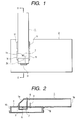
- Fig. 1 is a plan view of a converter for receiving a satellite broadcast in accordance with an embodiment mode example of the present invention.
- Fig. 2 is a sectional view along line II-II of Fig. 1.
- Fig. 3 is a perspective view of a waveguide arranged in the converter for receiving the satellite broadcast.
- Fig. 4 is a perspective view of the waveguide seen from the side opposed to Fig. 3.
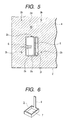
- Fig. 5 is a plan view of a circuit substrate arranged in the converter for receiving the satellite broadcast.
- Fig. 6 is a perspective view of a cover body arranged in the converter for receiving the satellite broadcast.
- the converter for receiving the satellite broadcast in accordance with this embodiment mode example has a waveguide 1 having an inclination face 1a on one end side thereof and formed in a square sleeve shape, and a circuit substrate 2 forming a converter circuit, etc. therein, a cover body 3 formed in a shape having a bottom, etc.
- the waveguide 1 is const ructed by bending and processing a metallic plate, and an end face on the side opposed to the inclination face 1a of this waveguide 1 is set to a front portion opening end 1b of a square shape.
- An unillustrated dielectric feeder is attached to this front portion opening end 1b.
- a radio wave transmitted from a satellite is guided from this dielectric feeder into the waveguide 1, and is then advanced toward the inclination face 1a as first and second linearly polarized waves perpendicular to each other. If a 90-degree phase changing portion is arranged in this dielectric feeder, a circularly polarized wave transmitted from the satellite is converted to a linearly polarized wave, and can be guided into the waveguide 1.
- a rectangular opening 1c is formed on one side face of the waveguide 1, and a hole 1d is formed on the other side face of the waveguide 1 opposed to this opening 1c.
- Plural leg pieces 1e, plural bending pieces 1f and one engaging piece 1g are formed on the periphery of the opening 1c. Each bending piece 1f is bent from the opening 1c toward the outside, but the engaging piece 1g is bent inside toward the opening 1c.
- the inclination face 1a crosses the tube axis of the waveguide 1 at an angle of about 45 degrees.
- the radio wave entering from the side of the front portion opening end 1b of the waveguide 1 is perpendicularly returned on the inclination face 1a, and is advanced in the direction of the opening 1c.
- a notch hole 2a is bored in the cir cuit substrate 2, and plural engaging holes 2b, a through hole 2c and a look-through hole 2d are respectively formed.
- the notch hole 2a is approximately formed in a rectangular shape, and a projecting piece 2e extended from a long side of the notch hole 2a to the center is formed. Further, a bridging piece 2f connected between short sides opposed to each other is formed.
- a ground conductor 4 is patterned and formed approximately in the entire area of the surface of this circuit substrate 2. This ground conductor 4 is extended onto the bridging piece 2f so that a reflecting pattern 5 is formed.
- This reflecting pattern 5 functions as a third short-circuited terminal, and both ends of the reflecting pattern 5 are connected to the ground through the ground conductor 4.
- a circuit element of the unillustrated converter circuit is mounted to the rear face of the circuit substrate 2.
- a second probe 6 connected to an input section of this converter circuit is patterned and formed on the projecting piece 2e. Namely, the reflecting pattern 5 and the second probe 6 are perpendicular to each other within the notch hole 2a.
- the cover body 3 is formed by bending and processing a metallic plate in a square sleeve shape, and its inner bottom face is set to a second short-circuited terminal 7.
- a first short-circuited terminal 8 projected in a band shape is integrally formed on one side face of the cover body 3.
- the engaging piece 1g of the waveguide 1 is engaged with one side face of the circuit substrate 2, and each bending piece 1f is soldered to the ground conductor 4 in a state in which each leg piece 1e is inserted into the corresponding engaging hole 2b.
- the waveguide 1 is placed and fixed onto the circuit substrate 2 such that its opening 1c is overlapped with the ground conductor 4.
- the opening 1c of the waveguide 1 is covered with the circuit substrate 2 in a portion except for the notch hole 2a.
- a rear portion opening end of the waveguide 1 is formed by the opening 1c overlapped with this notch hole 2a.
- a first probe 9 constructed by a pin member is inserted into the look-through hole 2d from the rear face side of the circuit substrate 2, and is then inserted into the waveguide 1. This first probe 9 is soldered to the input section of the above converter circuit formed in the circuit substrate 2.
- the cover body 3 is fixed to the rear face side of the circuit substrate 2 by inserting the first short-circuited terminal 8 of the cover body 3 into the hole 1d of the waveguide 1 from the through hole 2c of the circuit substrate 2, and soldering the tip portion of this first short-circuited terminal 8 to the outside face of the waveguide 1.
- the rear portion opening end of the waveguide 1 and the notch hole 2a of the circuit substrate 2 are covered with the cover body 3.
- the first short-circuited terminal 8 is arranged in the position separated by about ⁇ /4 in the advancing direction of the radio wave from the first probe 9 within the waveguide 1.
- This first short-circuited terminal 8 is arranged to reflect a first linearly polarized wave (e.g., a vertically polarized wave) advanced within the waveguide 1 and detect this first linearly polarized wave by the first probe 9.
- the first short-circuited terminal 8 and the first probe 9 are arranged in parallel with each other.
- the second short-circuited terminal 7 is arranged in the position separated by about ⁇ /4 in the advancing direction of the radio wave from the second probe 6 and the reflecting pattern (third short-circuited terminal) 5.
- a second linearly polarized wave e.g., a horizontally polarized wave
- the first short-circuited terminal 8 and the second short-circuited terminal 7 are set in the positions electrically separated by about ⁇ /2 with respect to the advancing direction of the radio wave to shorten the entire length of the waveguide 1. Accordingly, the portion between the first short-circuited terminal 8 and the reflecting pattern 5, and the portion between the reflecting pattern 5 and the second short-circuited terminal 7 are respectively set in the positions electrically separated by about ⁇ /4 with respect to the advancing direction of the radio wave. Further, a frame body 10 constructed by a metallic material is fixed onto the rear face side of the circuit substrate 2, and the above converter circuit formed on the rear face of the circuit substrate 2 is electrically shielded by covering an opening of this frame body 10 with a cover 11.
- the radio wave transmitted from the satellite enters the interior of the waveguide 1 from an unillustrated dielectric feeder attached to the front portion opening end 1b.
- this radio wave is advanced into the waveguide 1 as first and second linearly polarized waves perpendicular to each other, the first linearly polarized wave is reflected in the first short-circuited terminal 8, and is detected by the first probe 9.
- the second linearly polarized wave is directionally converted on the inclination face 1a of the waveguide 1, and is then reflected in the second short-circuited terminal 7 of the cover body 3, and is detected by the second probe 6 on the circuit substrate 2.
- These two orthogonal polarized wave signals detected by the first and second probes 9, 6 are frequency-converted to IF frequency signals by the above converter circuit formed in the circuit substrate 2, and are then outputted through an unillustrated output terminal.
- the first short-circuited terminal 8 and the sec ond short-circuited terminal 7 are set in the positions electrically separated by about ⁇ /2 with respect to the advancing direction of the radio wave.
- the portion between the first short-circuited terminal 8 and the reflecting pattern 5, and the portion between the reflecting pattern 5 and the second short-circuited terminal 7 are respectively set in the positions electrically separated by about ⁇ /4 with respect to the advancing direction of the radio wave.
- Fig. 7 typically shows the relation of the first short-circuited terminal 8, the second short-circuited terminal 7 and the reflecting pattern (third short-circuited terminal) 5.
- the second linearly polarized wave reflected in the second short-circuited terminal 7 and returned to the first short-circuited terminal 8 is inverted in phase between the second short-circuited terminal 7 and the reflecting pattern 5, and is also inverted in phase between the first short-circuited terminal 8 and the reflecting pattern 5. Therefore, no resonance is generated between the first short-circuited terminal 8 and the second short-circuited terminal 7. Namely, the reflecting pattern 5 as the third short-circuited terminal becomes a reactance component, and an unnecessary polarized wave is reflected. Therefore, an unnecessary resonance frequency can be removed from a receiving band of the used radio wave, and the deterioration of electricity supply efficiency of the second probe 6 can be prevented.
- the distance between the first short-circuited terminal 8 and the second short-circuited terminal 7 is set in the position electrically separated by about ⁇ /2 with respect to the advancing direction of the radio wave.
- the second probe 6 and the reflecting pattern (third short-circuited terminal) 5 are patterned and formed in directions perpendicular to each other in the circuit substrate 2 arranged between the first short-circuited terminal 8 and the second short-circuited terminal 7.
- the distance between the first short-circuited terminal 8 and the reflecting pattern 5, and the distance between the reflecting pattern 5 and the second short-circuited terminal 7 are respectively set in the positions electrically separated by about ⁇ /4 with respect to the advancing direction of the radio wave.
- the unnecessary resonance frequency can be removed by the using band by the reflecting pattern 5. Therefore, the entire length of the waveguide 1 is shortened and the waveguide 1 is made compact, and the deterioration of electricity supply efficiency can be prevented. Further, since the reflecting pattern 5 as the third short-circuited terminal is formed in the same circuit substrate 2 as the second probe 6, it is not necessary to separately arrange the third short-circuited terminal on purpose so that the number of parts is reduced and cost is reduced.
- the waveguide 1 having the inclination face 1a therein is used, and the converter for receiving the satellite broadcast having the circuit substrate 2 arranged in parallel with the tube axis of the waveguide 1 of such a corner type has been explained.
- the waveguide of a straight shape having no inclination face therein can be also used, and the present invention can be also applied to the converter for receiving the satellite broadcast having the circuit substrate arranged perpendicularly to the tube axis of the waveguide of such a linear type.
Landscapes
- Waveguide Switches, Polarizers, And Phase Shifters (AREA)
- Waveguide Aerials (AREA)
- Input Circuits Of Receivers And Coupling Of Receivers And Audio Equipment (AREA)
Abstract
A converter for receiving a satellite broadcast has a
waveguide (1) for advancing a radio wave entering a waveguide
tube as first and second linearly polarized waves perpendicular
to each other, a first probe (9) and a second probe (6) projected
into the tube of this waveguide and sequentially arranged along
the advancing direction of the radio wave, a first short-circuited
terminal (8) for reflecting the first linearly
polarized wave and detecting the first linearly polarized wave
by the first probe, a second short-circuited terminal (7) for
reflecting the second linearly polarized wave and detecting
the second linearly polarized wave by the second probe, and
a reflecting pattern (5) (third short-circuited terminal)
arranged between these first and second short-circuited
terminals. When the guide wavelength of the used radio wave
is set to λ, the distance between the first short-circuited
terminal and the second short-circuited terminal is set to
about λ/2, and the distance between the first short-circuited
terminal and the reflecting pattern, and the distance between
the reflecting pattern and the second short-circuited
terminal are respectively set to about λ/4.
Description
- The present invention relates to a converter for receiving a satellite broadcast which receives signals of two kinds of linearly polarized waves perpendicular to each other.
- Fig. 9 is a sectional view showing a conventional example of the converter for receiving the satellite broadcast of this kind. As shown in this figure, this converter for receiving the satellite broadcast has a
waveguide 100, a box body 101, acircuit substrate 102, acover body 103, etc. - The
waveguide 100 is formed in a sleeve shape opened at both ends thereof. Thewaveguide 100 has ahorn portion 100a on its front portion opening end side. A radio wave transmitted from a satellite enters from thishorn portion 100a to thewaveguide 100, and is then advanced toward a rear portion opening end as first and second linearly polarized waves perpendicular to each other. Thiswaveguide 100 and the box body 101 are integrated by a zinc die cast, an aluminum die cast, etc., and thecircuit substrate 102 is stored within the box body. Afirst probe 104 constructed by a pin member and a first short-circuited terminal 105 are inserted into thewaveguide 100 so as to be perpendicular to a tube axis. The rear end portion of thefirst probe 104 is soldered to the input section of an unillustrated converter circuit formed in thecircuit substrate 102. The first short-circuited terminal 105 is arranged to reflect a first linearly polarized wave (e.g., a horizontally polarized wave) advanced within thewaveguide 100, and detect this first linearly polarized wave by thefirst probe 104. When the guide wavelength of the used radio wave is set to λ, this first short-circuited terminal 105 is set in the position separated by about λ/4 from thefirst probe 104 in the advancing direction of the radio wave. - A
notch hole 102a opposed to a rear portion opening end of thewaveguide 100 is bored in thecircuit substrate 102. Asecond probe 106 is patterned and formed in a projectingpiece 102b projected toward the center of thisnotch hole 102a. Thissecond probe 106 is also connected to the input section of the above converter circuit, but is extended in the direction perpendicular to thefirst probe 104 within thewaveguide 100. Thecover body 103 is fixed into the box body 101 by a screw, etc. through thecircuit substrate 102. The rear portion opening end of thewaveguide 100 and thenotch hole 102a of thecircuit substrate 102 are closed by thiscover body 103. Thecover body 103 is formed in a shape having a bottom, and its inner bottom face is set to a second short-circuitedterminal 107. This second short-circuited terminal 107 is arranged to reflect a second linearly polarized wave (e.g., a vertically polarized wave) advanced within thewaveguide 100, and detect this second linearly polarized wave by thesecond probe 106. The second short-circuited terminal 107 is set to the position separated by about λ/4 from thesecond probe 106 in the advancing direction of the radio wave. - In the converter for receiving the satellite broadcast constructed in this way, when the radio wave transmitted from the satellite enters the
horn portion 100a and is advanced into thewaveguide 100 as the first and second linearly polarized waves perpendicular to each other, the first linearly polarized wave is reflected in the first short-circuited terminal 105 and is detected by thefirst probe 104. The second linearly polarized wave is reflected in the second short-circuited terminal 107 of thecover body 103, and is detected by thesecond probe 106. The two orthogonal polarized wave signals detected by these first andsecond probes circuit substrate 102, and are then outputted through an unillustrated output terminal. - In the above conventional converter for receiving the satellite broadcast, when the distance D between the first short-
circuited terminal 105 and the second short-circuited terminal 107 is set to a relation of λ/2 (D=λ/2), the phenomenon that one portion of the second linearly polarized wave reflected in the second short-circuited terminal 107 is resonated between the first short-circuited terminal 105 and the second short-circuited terminal 107 and its resonance frequency enters a receiving band of the used radio wave and deteriorates electricity supply efficiency, is generated as shown in Fig. 10. For such reasons, the distance D between the first short-circuited terminal 105 and the second short-circuited terminal 107 is conventionally set to a sufficiently large value with respect to λ/2. However, therefore, the degree of freedom in design is restricted, and the entire length of thewaveguide 100 is lengthened in the tube axis direction. Therefore, a problem exists in that compactness of the converter for receiving the satellite broadcast is prevented. - In consideration of such a real situation of the prior art, an object of the present invention is to provide a converter for receiving a satellite broadcast made compact without deteriorating electricity supply efficiency.
- To achieve the above object, the present invention resides in a converter for receiving a satellite broadcast characterized in that the converter comprises a waveguide for advancing a radio wave entering a waveguide tube as first and second linearly polarized waves perpendicular to each other, first and second probes projected into the tube of the waveguide and sequentially arranged along the advancing direction of the radio wave, a first short-circuited terminal for reflecting the first linearly polarized wave and detecting the first linearly polarized wave by the first probe, a second short-circuited terminal for reflecting the second linearly polarized wave and detecting the second linearly polarized wave by the second probe, and a third short-circuited terminal arranged between the first and second short-circuited terminals; wherein the distance between the first short-circuited terminal and the second short-circuited terminal is set to about λ/2, and the distance between the first short-circuited terminal and the third short-circuited terminal is set to about λ/4 when the guide wavelength of the used radio wave is set to λ.
- In the converter for receiving the satellite broadcast constructed in this way, even when the distance between the first short-circuited terminal and the second short-circuited terminal is set to about λ/2 and the entire length of the waveguide is shortened, an unnecessary resonance frequency can be removed from a receiving band of the used radio wave by the third short-circuited terminal arranged between the first short-circuited terminal and the second short-circuited terminal. Therefore, the converter can be made compact without deteriorating electricity supply efficiency.
- In the above construction, it is preferable that the second prove and the third short-circuited terminal are patterned and formed in directions perpendicular to each other in the same circuit substrate, and this circuit substrate is nipped and supported by a rear portion opening end of the waveguide and a cover body, and the second short-circuited terminal is formed on the inner bottom face of this cover body. When such a construction is adopted, the number of parts is reduced and cost is reduced. In this case, when both ends of the third short-circuited terminal are connected to the ground, the third short-circuited terminal becomes a reactance component and an unnecessary polarized wave can be reflected. Further, when only one end of the third short-circuited terminal is connected to the ground and the length of the third short-circuited terminal is set to about λ/4, the third short-circuited terminal becomes a reactance component and a capacity component, and an unnecessary polarized wave can be absorbed and damped.
- Embodiments of the present invention will now be described, by way of example, with reference to the accompanying diagrammatic drawings, in which:
- Fig. 1 is a plan view of a converter for receiving a satellite broadcast in accordance with an embodiment mode example of the present invention.
- Fig. 2 is a sectional view along line II-II of Fig. 1.
- Fig. 3 is a perspective view of a waveguide arranged in the converter for receiving the satellite broadcast.
- Fig. 4 is a perspective view of the waveguide seen from the side opposed to Fig. 3.
- Fig. 5 is a plan view of a circuit substrate arranged in the converter for receiving the satellite broadcast.
- Fig. 6 is a perspective view of a cover body arranged in the converter for receiving the satellite broadcast.
- Fig. 7 is an explanatory view showing the operating principle of a third short-circuited terminal.
- Fig. 8 is an explanatory view showing a modified example of the third short-circuited terminal.
- Fig. 9 is a sectional view of a converter for receiving the satellite broadcast in accordance with a conventional example.
- Fig. 10 is an explanatory view showing a problem point of the conventional example.
-
- The embodiment modes of the invention will next be explained with reference to the drawings. Fig. 1 is a plan view of a converter for receiving a satellite broadcast in accordance with an embodiment mode example of the present invention. Fig. 2 is a sectional view along line II-II of Fig. 1. Fig. 3 is a perspective view of a waveguide arranged in the converter for receiving the satellite broadcast. Fig. 4 is a perspective view of the waveguide seen from the side opposed to Fig. 3. Fig. 5 is a plan view of a circuit substrate arranged in the converter for receiving the satellite broadcast. Fig. 6 is a perspective view of a cover body arranged in the converter for receiving the satellite broadcast.
- The converter for receiving the satellite broadcast in accordance with this embodiment mode example has a
waveguide 1 having aninclination face 1a on one end side thereof and formed in a square sleeve shape, and acircuit substrate 2 forming a converter circuit, etc. therein, acover body 3 formed in a shape having a bottom, etc. - The
waveguide 1 is const ructed by bending and processing a metallic plate, and an end face on the side opposed to theinclination face 1a of thiswaveguide 1 is set to a frontportion opening end 1b of a square shape. An unillustrated dielectric feeder is attached to this frontportion opening end 1b. A radio wave transmitted from a satellite is guided from this dielectric feeder into thewaveguide 1, and is then advanced toward theinclination face 1a as first and second linearly polarized waves perpendicular to each other. If a 90-degree phase changing portion is arranged in this dielectric feeder, a circularly polarized wave transmitted from the satellite is converted to a linearly polarized wave, and can be guided into thewaveguide 1. As shown in Figs. 3 and 4, arectangular opening 1c is formed on one side face of thewaveguide 1, and ahole 1d is formed on the other side face of thewaveguide 1 opposed to this opening 1c.Plural leg pieces 1e,plural bending pieces 1f and oneengaging piece 1g are formed on the periphery of the opening 1c. Eachbending piece 1f is bent from the opening 1c toward the outside, but theengaging piece 1g is bent inside toward the opening 1c. Theinclination face 1a crosses the tube axis of thewaveguide 1 at an angle of about 45 degrees. The radio wave entering from the side of the frontportion opening end 1b of thewaveguide 1 is perpendicularly returned on theinclination face 1a, and is advanced in the direction of theopening 1c. - As shown in Fig. 5, a
notch hole 2a is bored in thecir cuit substrate 2, and plural engagingholes 2b, a throughhole 2c and a look-throughhole 2d are respectively formed. Thenotch hole 2a is approximately formed in a rectangular shape, and a projectingpiece 2e extended from a long side of thenotch hole 2a to the center is formed. Further, abridging piece 2f connected between short sides opposed to each other is formed. Aground conductor 4 is patterned and formed approximately in the entire area of the surface of thiscircuit substrate 2. Thisground conductor 4 is extended onto thebridging piece 2f so that a reflectingpattern 5 is formed. This reflectingpattern 5 functions as a third short-circuited terminal, and both ends of the reflectingpattern 5 are connected to the ground through theground conductor 4. In contrast to this, a circuit element of the unillustrated converter circuit is mounted to the rear face of thecircuit substrate 2. Asecond probe 6 connected to an input section of this converter circuit is patterned and formed on the projectingpiece 2e. Namely, the reflectingpattern 5 and thesecond probe 6 are perpendicular to each other within thenotch hole 2a. As shown in Fig. 6, thecover body 3 is formed by bending and processing a metallic plate in a square sleeve shape, and its inner bottom face is set to a second short-circuitedterminal 7. A first short-circuitedterminal 8 projected in a band shape is integrally formed on one side face of thecover body 3. - As shown in Figs. 1 and 2, the engaging
piece 1g of thewaveguide 1 is engaged with one side face of thecircuit substrate 2, and eachbending piece 1f is soldered to theground conductor 4 in a state in which eachleg piece 1e is inserted into the corresponding engaginghole 2b. Thus, thewaveguide 1 is placed and fixed onto thecircuit substrate 2 such that its opening 1c is overlapped with theground conductor 4. Thus, theopening 1c of thewaveguide 1 is covered with thecircuit substrate 2 in a portion except for thenotch hole 2a. A rear portion opening end of thewaveguide 1 is formed by the opening 1c overlapped with thisnotch hole 2a. Afirst probe 9 constructed by a pin member is inserted into the look-throughhole 2d from the rear face side of thecircuit substrate 2, and is then inserted into thewaveguide 1. Thisfirst probe 9 is soldered to the input section of the above converter circuit formed in thecircuit substrate 2. - Further, the
cover body 3 is fixed to the rear face side of thecircuit substrate 2 by inserting the first short-circuitedterminal 8 of thecover body 3 into thehole 1d of thewaveguide 1 from the throughhole 2c of thecircuit substrate 2, and soldering the tip portion of this first short-circuitedterminal 8 to the outside face of thewaveguide 1. Thus, the rear portion opening end of thewaveguide 1 and thenotch hole 2a of thecircuit substrate 2 are covered with thecover body 3. When the guide wavelength of a used radio wave is set to λ, the first short-circuitedterminal 8 is arranged in the position separated by about λ/4 in the advancing direction of the radio wave from thefirst probe 9 within thewaveguide 1. This first short-circuitedterminal 8 is arranged to reflect a first linearly polarized wave (e.g., a vertically polarized wave) advanced within thewaveguide 1 and detect this first linearly polarized wave by thefirst probe 9. The first short-circuitedterminal 8 and thefirst probe 9 are arranged in parallel with each other. Further, the second short-circuitedterminal 7 is arranged in the position separated by about λ/4 in the advancing direction of the radio wave from thesecond probe 6 and the reflecting pattern (third short-circuited terminal) 5. A second linearly polarized wave (e.g., a horizontally polarized wave) is reflected in the second short-circuitedterminal 7, and is detected by thesecond probe 6. In this embodiment mode example, the first short-circuitedterminal 8 and the second short-circuitedterminal 7 are set in the positions electrically separated by about λ/2 with respect to the advancing direction of the radio wave to shorten the entire length of thewaveguide 1. Accordingly, the portion between the first short-circuitedterminal 8 and the reflectingpattern 5, and the portion between the reflectingpattern 5 and the second short-circuitedterminal 7 are respectively set in the positions electrically separated by about λ/4 with respect to the advancing direction of the radio wave. Further, aframe body 10 constructed by a metallic material is fixed onto the rear face side of thecircuit substrate 2, and the above converter circuit formed on the rear face of thecircuit substrate 2 is electrically shielded by covering an opening of thisframe body 10 with a cover 11. - In the converter for receiving the satellite broadcast constructed in this way, the radio wave transmitted from the satellite enters the interior of the
waveguide 1 from an unillustrated dielectric feeder attached to the frontportion opening end 1b. When this radio wave is advanced into thewaveguide 1 as first and second linearly polarized waves perpendicular to each other, the first linearly polarized wave is reflected in the first short-circuitedterminal 8, and is detected by thefirst probe 9. Further, the second linearly polarized wave is directionally converted on theinclination face 1a of thewaveguide 1, and is then reflected in the second short-circuitedterminal 7 of thecover body 3, and is detected by thesecond probe 6 on thecircuit substrate 2. These two orthogonal polarized wave signals detected by the first andsecond probes circuit substrate 2, and are then outputted through an unillustrated output terminal. - Here, the first short-circuited
terminal 8 and the sec ond short-circuitedterminal 7 are set in the positions electrically separated by about λ/2 with respect to the advancing direction of the radio wave. The portion between the first short-circuitedterminal 8 and the reflectingpattern 5, and the portion between the reflectingpattern 5 and the second short-circuitedterminal 7 are respectively set in the positions electrically separated by about λ/4 with respect to the advancing direction of the radio wave. Fig. 7 typically shows the relation of the first short-circuitedterminal 8, the second short-circuitedterminal 7 and the reflecting pattern (third short-circuited terminal) 5. As shown in this figure, the second linearly polarized wave reflected in the second short-circuitedterminal 7 and returned to the first short-circuitedterminal 8 is inverted in phase between the second short-circuitedterminal 7 and the reflectingpattern 5, and is also inverted in phase between the first short-circuitedterminal 8 and the reflectingpattern 5. Therefore, no resonance is generated between the first short-circuitedterminal 8 and the second short-circuitedterminal 7. Namely, the reflectingpattern 5 as the third short-circuited terminal becomes a reactance component, and an unnecessary polarized wave is reflected. Therefore, an unnecessary resonance frequency can be removed from a receiving band of the used radio wave, and the deterioration of electricity supply efficiency of thesecond probe 6 can be prevented. - In the converter for receiving the satellite b roadcast in accordance with the above embodiment mode example, the distance between the first short-circuited
terminal 8 and the second short-circuitedterminal 7 is set in the position electrically separated by about λ/2 with respect to the advancing direction of the radio wave. Further, thesecond probe 6 and the reflecting pattern (third short-circuited terminal) 5 are patterned and formed in directions perpendicular to each other in thecircuit substrate 2 arranged between the first short-circuitedterminal 8 and the second short-circuitedterminal 7. Further, the distance between the first short-circuitedterminal 8 and the reflectingpattern 5, and the distance between the reflectingpattern 5 and the second short-circuitedterminal 7 are respectively set in the positions electrically separated by about λ/4 with respect to the advancing direction of the radio wave. Accordingly, the unnecessary resonance frequency can be removed by the using band by the reflectingpattern 5. Therefore, the entire length of thewaveguide 1 is shortened and thewaveguide 1 is made compact, and the deterioration of electricity supply efficiency can be prevented. Further, since the reflectingpattern 5 as the third short-circuited terminal is formed in thesame circuit substrate 2 as thesecond probe 6, it is not necessary to separately arrange the third short-circuited terminal on purpose so that the number of parts is reduced and cost is reduced. - In the above embodiment mode example, the case in which both the ends of the reflecting
pattern 5 as the third short-circuited terminal are connected to the ground, has been explained. However, as shown in Fig. 8, only one end of the reflectingpattern 5 set to about λ/4 in length may be also connected to the ground. In this case, the reflectingpattern 5 becomes a reactance component and a capacity component, and the unnecessary polarized wave can be absorbed and damped. - Further, in the above embodiment mode example, the
waveguide 1 having theinclination face 1a therein is used, and the converter for receiving the satellite broadcast having thecircuit substrate 2 arranged in parallel with the tube axis of thewaveguide 1 of such a corner type has been explained. However, the waveguide of a straight shape having no inclination face therein can be also used, and the present invention can be also applied to the converter for receiving the satellite broadcast having the circuit substrate arranged perpendicularly to the tube axis of the waveguide of such a linear type.
Claims (4)
- A converter for receiving a satellite broadcast characterized in that the converter comprises a waveguide for advancing a radio wave entering a waveguide tube as first and second linearly polarized waves perpendicular to each other, first and second probes projected into the tube of said waveguide and sequentially arranged along the advancing direction of the radio wave, a first short-circuited terminal for reflecting said first linearly polarized wave and detecting said first linearly polarized wave by said first probe, a second short-circuited terminal for reflecting said second linearly polarized wave and detecting said second linearly polarized wave by said second probe, and a third short-circuited terminal arranged between said first and second short-circuited terminals;
wherein the distance between said first short-circuited terminal and said second short-circuited terminal is set to about λ/2, and the distance between said first short-circuited terminal and said third short-circuited terminal is set to about λ/4 when the guide wavelength of the used radio wave is set to λ. - The converter for receiving the satellite broadcast according to claim 1, wherein said second prove and said third short-circuited terminal are patterned and formed in directions perpendicular to each other in the same circuit substrate, and this circuit substrate is nipped and supported by a rear portion opening end of said waveguide and a cover body, and said second short-circuited terminal is formed on the inner bottom face of this cover body.
- The converter for receiving the satellite broadcast according to claim 2, wherein both ends of said third short-circuited terminal are connected to the ground.
- The converter for receiving the satellite broadcast according to claim 2, wherein only one end of said third short-circuited terminal is connected to the ground, and the length of the third short-circuited terminal is set to about λ/4.
Applications Claiming Priority (2)
| Application Number | Priority Date | Filing Date | Title |
|---|---|---|---|
| JP2002227406 | 2002-08-05 | ||
| JP2002227406A JP4027175B2 (en) | 2002-08-05 | 2002-08-05 | Converter for satellite broadcasting reception |
Publications (1)
| Publication Number | Publication Date |
|---|---|
| EP1388908A1 true EP1388908A1 (en) | 2004-02-11 |
Family
ID=30437726
Family Applications (1)
| Application Number | Title | Priority Date | Filing Date |
|---|---|---|---|
| EP03254614A Withdrawn EP1388908A1 (en) | 2002-08-05 | 2003-07-24 | Converter for receiving satellite broadcast |
Country Status (3)
| Country | Link |
|---|---|
| EP (1) | EP1388908A1 (en) |
| JP (1) | JP4027175B2 (en) |
| CN (1) | CN1258267C (en) |
Families Citing this family (1)
| Publication number | Priority date | Publication date | Assignee | Title |
|---|---|---|---|---|
| JP4931353B2 (en) * | 2005-01-26 | 2012-05-16 | 勲 太田 | Microwave transceiver and rangefinder |
Citations (6)
| Publication number | Priority date | Publication date | Assignee | Title |
|---|---|---|---|---|
| US2985852A (en) * | 1956-01-04 | 1961-05-23 | Gen Electric Co Ltd | Apparatus of the kind including a waveguide |
| JPH02171001A (en) * | 1988-12-23 | 1990-07-02 | Matsushita Electric Works Ltd | Strip line-waveguide converter |
| EP0552944A1 (en) * | 1992-01-21 | 1993-07-28 | Sharp Kabushiki Kaisha | Waveguide to coaxial adaptor and converter for antenna for satellite broadcasting including such waveguide |
| US5585768A (en) * | 1995-07-12 | 1996-12-17 | Microelectronics Technology Inc. | Electromagnetic wave conversion device for receiving first and second signal components |
| GB2334153A (en) * | 1995-07-19 | 1999-08-11 | Alps Electric Co Ltd | Outdoor converter for receiving satellite broadcast |
| EP1091443A2 (en) * | 1999-10-04 | 2001-04-11 | Alps Electric Co., Ltd. | Satellite broadcast receiving converter |
-
2002
- 2002-08-05 JP JP2002227406A patent/JP4027175B2/en not_active Expired - Fee Related
-
2003
- 2003-07-24 EP EP03254614A patent/EP1388908A1/en not_active Withdrawn
- 2003-08-05 CN CN 03152589 patent/CN1258267C/en not_active Expired - Fee Related
Patent Citations (6)
| Publication number | Priority date | Publication date | Assignee | Title |
|---|---|---|---|---|
| US2985852A (en) * | 1956-01-04 | 1961-05-23 | Gen Electric Co Ltd | Apparatus of the kind including a waveguide |
| JPH02171001A (en) * | 1988-12-23 | 1990-07-02 | Matsushita Electric Works Ltd | Strip line-waveguide converter |
| EP0552944A1 (en) * | 1992-01-21 | 1993-07-28 | Sharp Kabushiki Kaisha | Waveguide to coaxial adaptor and converter for antenna for satellite broadcasting including such waveguide |
| US5585768A (en) * | 1995-07-12 | 1996-12-17 | Microelectronics Technology Inc. | Electromagnetic wave conversion device for receiving first and second signal components |
| GB2334153A (en) * | 1995-07-19 | 1999-08-11 | Alps Electric Co Ltd | Outdoor converter for receiving satellite broadcast |
| EP1091443A2 (en) * | 1999-10-04 | 2001-04-11 | Alps Electric Co., Ltd. | Satellite broadcast receiving converter |
Non-Patent Citations (1)
| Title |
|---|
| PATENT ABSTRACTS OF JAPAN vol. 014, no. 437 (E - 0980) 19 September 1990 (1990-09-19) * |
Also Published As
| Publication number | Publication date |
|---|---|
| CN1258267C (en) | 2006-05-31 |
| JP2004072319A (en) | 2004-03-04 |
| JP4027175B2 (en) | 2007-12-26 |
| CN1481092A (en) | 2004-03-10 |
Similar Documents
| Publication | Publication Date | Title |
|---|---|---|
| US7091920B2 (en) | Circular polarization slot antenna apparatus capable of being easily miniaturized | |
| US6437753B2 (en) | Primary radiator suitable for size reduction and preventing deterioration of cross polarization characteristic | |
| EP0073511B1 (en) | Satellite broadcasting receiver | |
| US5363105A (en) | Structure of multi-band microwave detector | |
| JPH06164217A (en) | Waveguide/microstrip converter | |
| US7136024B2 (en) | Slot antenna having high gain in zenith direction | |
| EP1339135B1 (en) | Converter for receiving satellite broadcast signals from a plurality of satellites | |
| US6778146B2 (en) | Satellite broadcast reception converter suitable for miniaturization | |
| JPH09246816A (en) | Waveguide-microstrip line converter | |
| EP1465282A1 (en) | Primary horn | |
| JPH08191211A (en) | Antenna | |
| EP1388909B1 (en) | Converter for receiving satellite broadcast | |
| JP4027175B2 (en) | Converter for satellite broadcasting reception | |
| US5874922A (en) | Antenna | |
| JP2003243902A (en) | Converter for receiving satellite broadcast | |
| JPH01309401A (en) | Triplate microstrip line converter | |
| JP4027244B2 (en) | Converter for satellite broadcasting reception | |
| US6130649A (en) | Polarizer for exciting an antenna | |
| JP2699462B2 (en) | Satellite broadcast receiving converter | |
| US6445356B1 (en) | Primary radiator having reduced side lobe | |
| GB2334153A (en) | Outdoor converter for receiving satellite broadcast | |
| JP4103330B2 (en) | NRD guide L type antenna element | |
| JP3076459B2 (en) | Coaxial-waveguide converter | |
| JPH05267903A (en) | Coaxial waveguide converter and converter for satellite broadcasting antenna including the same | |
| JP2001085933A (en) | Primary radiator |
Legal Events
| Date | Code | Title | Description |
|---|---|---|---|
| PUAI | Public reference made under article 153(3) epc to a published international application that has entered the european phase |
Free format text: ORIGINAL CODE: 0009012 |
|
| AK | Designated contracting states |
Kind code of ref document: A1 Designated state(s): AT BE BG CH CY CZ DE DK EE ES FI FR GB GR HU IE IT LI LU MC NL PT RO SE SI SK TR |
|
| AX | Request for extension of the european patent |
Extension state: AL LT LV MK |
|
| 17P | Request for examination filed |
Effective date: 20040315 |
|
| 17Q | First examination report despatched |
Effective date: 20040414 |
|
| AKX | Designation fees paid |
Designated state(s): DE FR GB |
|
| STAA | Information on the status of an ep patent application or granted ep patent |
Free format text: STATUS: THE APPLICATION IS DEEMED TO BE WITHDRAWN |
|
| 18D | Application deemed to be withdrawn |
Effective date: 20050426 |