EP1388650A1 - Exhaust manifold collecting part connection structure of multi-cylinder internal combustion engine - Google Patents
Exhaust manifold collecting part connection structure of multi-cylinder internal combustion engine Download PDFInfo
- Publication number
- EP1388650A1 EP1388650A1 EP02707222A EP02707222A EP1388650A1 EP 1388650 A1 EP1388650 A1 EP 1388650A1 EP 02707222 A EP02707222 A EP 02707222A EP 02707222 A EP02707222 A EP 02707222A EP 1388650 A1 EP1388650 A1 EP 1388650A1
- Authority
- EP
- European Patent Office
- Prior art keywords
- flange
- exhaust manifold
- collecting pipe
- combustion engine
- internal combustion
- Prior art date
- Legal status (The legal status is an assumption and is not a legal conclusion. Google has not performed a legal analysis and makes no representation as to the accuracy of the status listed.)
- Granted
Links
Images



Classifications
-
- F—MECHANICAL ENGINEERING; LIGHTING; HEATING; WEAPONS; BLASTING
- F16—ENGINEERING ELEMENTS AND UNITS; GENERAL MEASURES FOR PRODUCING AND MAINTAINING EFFECTIVE FUNCTIONING OF MACHINES OR INSTALLATIONS; THERMAL INSULATION IN GENERAL
- F16L—PIPES; JOINTS OR FITTINGS FOR PIPES; SUPPORTS FOR PIPES, CABLES OR PROTECTIVE TUBING; MEANS FOR THERMAL INSULATION IN GENERAL
- F16L27/00—Adjustable joints; Joints allowing movement
- F16L27/02—Universal joints, i.e. with mechanical connection allowing angular movement or adjustment of the axes of the parts in any direction
- F16L27/04—Universal joints, i.e. with mechanical connection allowing angular movement or adjustment of the axes of the parts in any direction with partly-spherical engaging surfaces
- F16L27/053—Universal joints, i.e. with mechanical connection allowing angular movement or adjustment of the axes of the parts in any direction with partly-spherical engaging surfaces held in place by bolts passing through flanges
-
- F—MECHANICAL ENGINEERING; LIGHTING; HEATING; WEAPONS; BLASTING
- F01—MACHINES OR ENGINES IN GENERAL; ENGINE PLANTS IN GENERAL; STEAM ENGINES
- F01N—GAS-FLOW SILENCERS OR EXHAUST APPARATUS FOR MACHINES OR ENGINES IN GENERAL; GAS-FLOW SILENCERS OR EXHAUST APPARATUS FOR INTERNAL-COMBUSTION ENGINES
- F01N13/00—Exhaust or silencing apparatus characterised by constructional features
- F01N13/08—Other arrangements or adaptations of exhaust conduits
-
- F—MECHANICAL ENGINEERING; LIGHTING; HEATING; WEAPONS; BLASTING
- F01—MACHINES OR ENGINES IN GENERAL; ENGINE PLANTS IN GENERAL; STEAM ENGINES
- F01N—GAS-FLOW SILENCERS OR EXHAUST APPARATUS FOR MACHINES OR ENGINES IN GENERAL; GAS-FLOW SILENCERS OR EXHAUST APPARATUS FOR INTERNAL-COMBUSTION ENGINES
- F01N13/00—Exhaust or silencing apparatus characterised by constructional features
- F01N13/08—Other arrangements or adaptations of exhaust conduits
- F01N13/10—Other arrangements or adaptations of exhaust conduits of exhaust manifolds
-
- F—MECHANICAL ENGINEERING; LIGHTING; HEATING; WEAPONS; BLASTING
- F01—MACHINES OR ENGINES IN GENERAL; ENGINE PLANTS IN GENERAL; STEAM ENGINES
- F01N—GAS-FLOW SILENCERS OR EXHAUST APPARATUS FOR MACHINES OR ENGINES IN GENERAL; GAS-FLOW SILENCERS OR EXHAUST APPARATUS FOR INTERNAL-COMBUSTION ENGINES
- F01N13/00—Exhaust or silencing apparatus characterised by constructional features
- F01N13/18—Construction facilitating manufacture, assembly, or disassembly
- F01N13/1805—Fixing exhaust manifolds, exhaust pipes or pipe sections to each other, to engine or to vehicle body
- F01N13/1811—Fixing exhaust manifolds, exhaust pipes or pipe sections to each other, to engine or to vehicle body with means permitting relative movement, e.g. compensation of thermal expansion or vibration
-
- F—MECHANICAL ENGINEERING; LIGHTING; HEATING; WEAPONS; BLASTING
- F01—MACHINES OR ENGINES IN GENERAL; ENGINE PLANTS IN GENERAL; STEAM ENGINES
- F01N—GAS-FLOW SILENCERS OR EXHAUST APPARATUS FOR MACHINES OR ENGINES IN GENERAL; GAS-FLOW SILENCERS OR EXHAUST APPARATUS FOR INTERNAL-COMBUSTION ENGINES
- F01N13/00—Exhaust or silencing apparatus characterised by constructional features
- F01N13/18—Construction facilitating manufacture, assembly, or disassembly
- F01N13/1805—Fixing exhaust manifolds, exhaust pipes or pipe sections to each other, to engine or to vehicle body
- F01N13/1827—Sealings specially adapted for exhaust systems
-
- F—MECHANICAL ENGINEERING; LIGHTING; HEATING; WEAPONS; BLASTING
- F01—MACHINES OR ENGINES IN GENERAL; ENGINE PLANTS IN GENERAL; STEAM ENGINES
- F01N—GAS-FLOW SILENCERS OR EXHAUST APPARATUS FOR MACHINES OR ENGINES IN GENERAL; GAS-FLOW SILENCERS OR EXHAUST APPARATUS FOR INTERNAL-COMBUSTION ENGINES
- F01N2450/00—Methods or apparatus for fitting, inserting or repairing different elements
- F01N2450/24—Methods or apparatus for fitting, inserting or repairing different elements by bolts, screws, rivets or the like
-
- F—MECHANICAL ENGINEERING; LIGHTING; HEATING; WEAPONS; BLASTING
- F01—MACHINES OR ENGINES IN GENERAL; ENGINE PLANTS IN GENERAL; STEAM ENGINES
- F01N—GAS-FLOW SILENCERS OR EXHAUST APPARATUS FOR MACHINES OR ENGINES IN GENERAL; GAS-FLOW SILENCERS OR EXHAUST APPARATUS FOR INTERNAL-COMBUSTION ENGINES
- F01N2470/00—Structure or shape of exhaust gas passages, pipes or tubes
- F01N2470/06—Tubes being formed by assembly of stamped or otherwise deformed sheet-metal
-
- F—MECHANICAL ENGINEERING; LIGHTING; HEATING; WEAPONS; BLASTING
- F01—MACHINES OR ENGINES IN GENERAL; ENGINE PLANTS IN GENERAL; STEAM ENGINES
- F01N—GAS-FLOW SILENCERS OR EXHAUST APPARATUS FOR MACHINES OR ENGINES IN GENERAL; GAS-FLOW SILENCERS OR EXHAUST APPARATUS FOR INTERNAL-COMBUSTION ENGINES
- F01N2530/00—Selection of materials for tubes, chambers or housings
- F01N2530/26—Multi-layered walls
Definitions
- the present invention relates to a connecting structure for connecting an exhaust manifold for a multicylinder internal combustion engine to a flange of a spherical joint for connecting an exhaust pipe to the exhaust manifold.
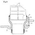
- Fig. 8 showing a conventional exhaust manifold connecting structure
- the upstream ends of branch tubes 01 of an exhaust manifold are connected to exhaust passages connected to the cylinders, not shown, of a multicylinder internal combustion engine.
- Downstream ends of the branch tubes 01 are gathered and are inserted in a manifold body 02, and the manifold body 02 is fitted in an outer pipe 03.
- One flange 04 of a spherical joint is put on and welded to a part near the branch tubes 01 of the outer pipe 03.
- a stay 05 for holding an exhaust manifold cover, not shown, is welded to the flange 04.
- a method of manufacturing the conventional exhaust manifold connecting structure shown in Fig. 8 winds a heat insulating mesh 06 around the manifold body 02, fits the manifold body 02 in the outer pipe 03, connects the manifold body 02 and the outer pipe 03 temporarily by spot welding or the like, welds the outer pipe 03 to the flange 04, gathers the four branch tubes 01 closely, inserts the gathered branch tubes 01 in the upstream end of the manifold body 02, and welds the respective brims of the manifold body 02 and the outer pipe 03, and the branch tubes 01 together.
- the method needs three welding processes. Therefore the method has many steps and the productivity thereof is low.
- the flange 04 formed from a thick plate is heavy, has a large thermal capacity and a narrow surface area. Therefore, the flange 04 has bad heat radiating property, increases thermal load on the spherical joint, and affects adversely to the durability of gaskets.
- an exhaust manifold connecting structure includes: a collecting pipe collectively holding branch tubes of an exhaust manifold for a multicylinder internal combustion engine; and a spherical joint connecting the collecting pipe and an exhaust pipe; wherein the collecting pipe is a double-wall pipe structure including a collecting pipe body, and an outer pipe put on the collecting pipe body; a tubular connecting part of a first flange included in the spherical joint is put on the outer pipe; and the collecting pipe body, the outer pipe and the tubular connecting part of the first flange are joined together by welding.
- the exhaust manifold connecting structure of the present invention can be fabricated by joining together the collecting pipe body, the outer pipe and the flange by a single welding process without temporarily connecting the collecting pipe body and the outer pipe, which reduces work and costs necessary for fabricating the exhaust manifold connecting structure.
- the outer pipe has a short length and is light.
- the first flange of the spherical joint may be formed by press working, and a peripheral part of the first flange may be bent toward an upstream side with respect to an exhaust direction.
- the thin first flange formed by press working and having the peripheral part thus bent has high strength and rigidity, which enables the further reduction of the weight of the exhaust manifold connecting structure. Since the peripheral part of the first flange is bent toward the upstream side, heat radiation from a connecting part on the side of a spherical gasket can be enhanced, heat radiating area can be increased to enhance heat radiation, and the durability of the spherical gasket can be improved.
- the first flange of the spherical joint may have a part serving as a stay for holding an exhaust manifold cover.
- the exhaust manifold cover can be easily and firmly attached to the first flange to heat-insulate the exhaust manifold effectively.
- the number of parts of the exhaust manifold connecting structure can be further reduced and the costs can be reduced accordingly.
- An annular space may be formed between the collecting pipe body and a downstream part of the outer pipe.
- the annular space reduces heat transfer to the gasket.
- the respective upstream parts of the collecting pipe body, the outer pipe and the tubular connecting part of the first flange are welded together.
- the spherical joint may be provided with a second flange opposite to the flange, and a gasket may be interposed between the tubular connecting part of the first flange and a central part of the second flange so as to be fitted on a part corresponding to the annular space of the outer pipe.
- the tubular connecting part of the first flange may be connected to a body of the flange by its annular part radially extending from the tubular connecting part, and a taper part having the shape of a truncated cone and surrounding the tubular connecting part.
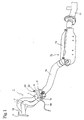
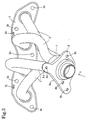
- An exhaust manifold 1 has, for example, four branch tubes 2. Upstream ends of the branch tubes 2 are joined to a manifold flange 3 of a shape shown in Fig. 3 so as to be connected to openings, not shown, formed in the manifold flange 3, respectively.
- the manifold flange 3 is fastened to the cylinder head of a four-cylinder straight internal combustion engine mounted on a vehicle with bolts, not shown, screwed through bolt holes 3a in threaded holes formed in the cylinder head so that the four branch tubes 2 communicate with the four exhaust ports, not shown, of the cylinder head, respectively.
- Downstream end parts of the branch tubes 2 of the exhaust manifold 1 are gathered in a single big pipe, and the big pipe is fitted in a collecting pipe 4.
- the collecting pipe 4 is connected to an upstream end part of an exhaust pipe 14 by a spherical joint 7.
- a downstream end part of the exhaust pipe 14 is connected to an upstream end part of a catalytic converter case 16 included in a catalytic converter 15.
- a downstream end part of the exhaust gas purifier case 16 is connected to a muffler, not shown, by a connecting pipe 17.
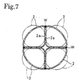
- Downstream end parts of the four branch tubes 2 are shaped by drawing in a sectional shape substantially resembling a quadrant as shown in Fig. 7.
- the downstream end parts thus shaped of the four branch tubes 2 are gathered so that the flat walls 2a of the adjacent downstream end parts are in close contact with each other, and the downstream end parts are welded together to form the single, big pipe.
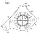
- the collecting pipe 4 includes a collecting pipe body 5, and an outer pipe 6 surrounding the collecting pipe body 5 so as to define an annular gap C (Fig. 5) between the collecting pipe body 5 and the outer pipe 6.
- the annular gap C serves as a heat insulating air layer for the collecting pipe 4.
- the annular gap C can be formed by reducing a downstream end part of the collecting pipe body 5.
- the spherical joint 7 includes an upstream flange 8 formed by subjecting a sheet to press working.
- the upstream flange 8 has a peripheral part 8a extending upstream substantially perpendicularly to a main part.
- the upstream flange 8 is provided with two bolt holes 8b point-symmetrical with respect to the center axis of the collecting pipe 4, and a bolt hole 8c for fastening a stay to the upstream flange 8.
- a manifold cover holding part 8d provided with a bolt hole 8e is formed integrally with the upstream flange 8.
- nuts 10 are attached by welding or the like to the upper surface of the upstream flange 8 in alignment with the bolt holes 8b, 8c and 8e.
- a tubular boss 8f extending perpendicularly upstream is formed by deep-drawing a central part of the upstream flange 8, an annular part 8g extends radially from the tubular boss 8f, and a taper part 8h having the shape of a truncated cone extends from the annular part 8g
- the spherical joint 7 includes a downstream flange 11 formed by subjecting a sheet to press working.
- the downstream flange 11 is put on and welded to an upstream end part of the exhaust pipe 14.
- the downstream flange 11 has a peripheral part 11a extending downstream substantially perpendicularly to a main part.
- a concave, spherical bearing part 11b concave toward the upstream side is formed in a central part of the downstream flange 11.
- the downstream flange 11 is provided with bolt holes 11c respectively corresponding to the bolt holes 8b of the upstream flange 8.
- a spherical gasket 12 is put on a downstream part 6a of the outer pipe 6 with its upstream end surface 12a in contact with the annular part 8g of the upstream flange 8.
- the concave, spherical bearing part 11b of the downstream flange 11 is in contact with a convex, spherical part 12b of the spherical gasket 12.
- the spherical gasket 12 is put on the downstream part 6a of the outer tube 6 corresponding to the annular gap C.
- Bolts 9 are passed through the bolt holes 11c of the downstream flange 11 from the downstream side toward the upstream side of the exhaust pipe 14, and are screwed in the nuts 10.
- Compression springs 13 are extended between the heads 9a of the bolts 9, and the downstream flange 11 to form the spherical joint 7.
- a bolt 19 is passed through the bolt hole 8c of the upstream flange 8 and a bolt hole, not shown, formed in an upper end part of a stay 18, and is screwed in the nut 10 attached to the upstream flange 8 in alignment with the bolt hole 8c.
- the manifold flange 3 is provided in its upper edge part with two bolt holes 3b for fastening an exhaust manifold cover.
- nuts 10 are attached to the manifold flange 3 in alignment with the bolt holes 3b.
- Bolts 20 are passed through the bolt holes of the exhaust manifold cover, not shown, and the bolt holes 3b of the manifold flange 3 and the bolt hole 8e of the upstream flange 8, and are screwed in the nuts 10 to hold the exhaust manifold cover, not shown, firmly on the manifold flange 3 and the upstream flange 8.
- the exhaust manifold connecting structure in the embodiment shown in Figs. 1 to 7 holds the exhaust manifold 1 firmly and stably on the internal combustion engine, not shown, by the manifold flange 3 and the stay 18.
- the internal combustion engine, not shown, and the catalytic converter 15 are mounted on the body of the vehicle.
- the spherical joint 7 is capable of smoothly absorbing change in its position due to the thermal expansion of the exhaust manifold 1 and the exhaust pipe 14 caused by the heat of a combustion gas flowing through the exhaust manifold 1 and the exhaust pipe 14.
- the outer pipe 6 Since the upstream end part of the outer pipe 6 and the upstream end of the tubular boss 8f of the upstream flange 8 are joined to the outer circumference of the collecting pipe body 5 by a weld W1, the outer pipe 6 does not need to be attached temporarily to the collecting pipe body 5, which reduces work and costs necessary for fabricating the exhaust manifold connecting structure.
- the upstream flange 8 is formed from a sheet and has a large surface area, the taper part 8h having the shape of a truncated cone protrudes downstream, and the annular part 8g formed at the extremity of the taper part 8h is in contact with the spherical gasket 12, the upstream flange 8 is capable of satisfactorily radiating heat. Since the downstream part 6a of the outer tube 6 on which the spherical gasket 12 is put is separated from the collecting pipe body 5, heat is transferred to the spherical gasket 12 at a low heat transfer rate and hence thermal load on the spherical gasket 12 is small. Consequently, the durability of the spherical gasket 12 is improved greatly.
- the upstream flange 8 formed from a sheet by press working is lightweight, strong and rigid.
- upstream flange 8 is integrally provided with the manifold cover holding part 8d provided with the bolt hole 8e, the number of parts is reduced, which contributes to cutting the costs.
Landscapes
- Engineering & Computer Science (AREA)
- General Engineering & Computer Science (AREA)
- Mechanical Engineering (AREA)
- Chemical & Material Sciences (AREA)
- Combustion & Propulsion (AREA)
- Exhaust Silencers (AREA)
- Joints Allowing Movement (AREA)
Abstract
Description
Claims (7)
- An exhaust manifold connecting structure for a multicylinder internal combustion engine, comprising:wherein the collecting pipe is a double-wall pipe structure including a collecting pipe body, and an outer pipe put on the collecting pipe body; a tubular connecting part of a first flange included in the spherical joint is put on the outer pipe; and the collecting pipe body, the outer pipe and the tubular connecting part of the first flange are joined together by welding.a collecting pipe collectively holding branch tubes of an exhaust manifold of the multicylinder internal combustion engine; anda spherical joint connecting the collecting pipe and an exhaust pipe;
- The exhaust manifold connecting structure for a multicylinder internal combustion engine according to claim 1, wherein the first flange of the spherical joint is formed by press working, and a peripheral part of the first flange is be bent toward an upstream side with respect to an exhaust direction.
- The exhaust manifold connecting structure for a multicylinder internal combustion engine according to claim 2, wherein the first flange of the spherical joint has a part serving as a stay for holding an exhaust manifold cover.
- The exhaust manifold connecting structure for a multicylinder internal combustion engine according to claim 1, wherein an annular space is formed between the collecting pipe body and a downstream part of the outer pipe.
- The exhaust manifold connecting structure for a multicylinder internal combustion engine according to claim 1, wherein the respective upstream parts of the collecting pipe body, the outer pipe and the tubular connecting part of the first flange are welded together.
- The exhaust manifold connecting structure for a multicylinder internal combustion engine according to claim 1, wherein the spherical joint includes a second flange opposite to the flange, and a gasket is interposed between the tubular connecting part of the first flange and a central part of the second flange so as to be fitted on a part corresponding to the annular space of the outer pipe.
- The exhaust manifold connecting structure for a multicylinder internal combustion engine according to claim 1, wherein the tubular connecting part of the first flange is connected to a body of the first flange by an annular part radially extending from the tubular connecting part, and a taper part having the shape of a truncated cone and surrounding the tubular connecting part.
Applications Claiming Priority (3)
| Application Number | Priority Date | Filing Date | Title |
|---|---|---|---|
| JP2001143848 | 2001-05-14 | ||
| JP2001143848A JP3680993B2 (en) | 2001-05-14 | 2001-05-14 | Exhaust manifold assembly connection structure for multi-cylinder internal combustion engines |
| PCT/JP2002/003078 WO2002092973A1 (en) | 2001-05-14 | 2002-03-28 | Exhaust manifold collecting part connection structure of multi-cylinder internal combustion engine |
Publications (3)
| Publication Number | Publication Date |
|---|---|
| EP1388650A1 true EP1388650A1 (en) | 2004-02-11 |
| EP1388650A4 EP1388650A4 (en) | 2004-07-14 |
| EP1388650B1 EP1388650B1 (en) | 2007-02-21 |
Family
ID=18989920
Family Applications (1)
| Application Number | Title | Priority Date | Filing Date |
|---|---|---|---|
| EP02707222A Expired - Lifetime EP1388650B1 (en) | 2001-05-14 | 2002-03-28 | Exhaust manifold collecting part connection structure of multi-cylinder internal combustion engine |
Country Status (9)
| Country | Link |
|---|---|
| EP (1) | EP1388650B1 (en) |
| JP (1) | JP3680993B2 (en) |
| CN (1) | CN100348842C (en) |
| AU (1) | AU2002241318B2 (en) |
| BR (1) | BR0205276B1 (en) |
| DE (1) | DE60218298T2 (en) |
| MY (1) | MY135123A (en) |
| TW (1) | TW550335B (en) |
| WO (1) | WO2002092973A1 (en) |
Cited By (1)
| Publication number | Priority date | Publication date | Assignee | Title |
|---|---|---|---|---|
| FR2883031A1 (en) * | 2005-03-08 | 2006-09-15 | Renault Sas | FLANGE EXHAUST INTERFACE |
Families Citing this family (12)
| Publication number | Priority date | Publication date | Assignee | Title |
|---|---|---|---|---|
| FR2849911B1 (en) * | 2003-01-14 | 2005-03-04 | Siemens Vdo Automotive | SPARK PLUG FOR INTERNAL COMBUSTION ENGINE EQUIPPED WITH A COMBUSTION CHAMBER PRESSURE SENSOR |
| DE602004006698T2 (en) | 2003-12-01 | 2007-10-04 | Nissan Motor Co., Ltd., Yokohama | Exhaust manifold for an internal combustion engine |
| JP5401944B2 (en) | 2008-11-25 | 2014-01-29 | コベルコ建機株式会社 | Muffler mounting device for construction machinery |
| JP5616194B2 (en) * | 2010-01-14 | 2014-10-29 | 株式会社クボタ | Engine with exhaust treatment device |
| CN104613261A (en) * | 2010-03-24 | 2015-05-13 | 仓敷化工株式会社 | Flexible joint |
| JP6490957B2 (en) * | 2014-12-17 | 2019-03-27 | フタバ産業株式会社 | Valve device and exhaust heat recovery device |
| JP6594055B2 (en) * | 2015-06-24 | 2019-10-23 | オイレス工業株式会社 | Gasket unit and spherical joint unit |
| DE102015224453A1 (en) * | 2015-12-07 | 2017-06-08 | Eberspächer Exhaust Technology GmbH & Co. KG | Silencer and manufacturing process |
| US10753516B2 (en) * | 2016-11-23 | 2020-08-25 | Ford Global Technologies, Llc | Flared exhaust gas pressure tube having keyed washer |
| WO2019222306A2 (en) | 2018-05-15 | 2019-11-21 | Cummins Inc. | Dual-wall integrated flange joint |
| CN210317447U (en) * | 2019-06-13 | 2020-04-14 | 赛格威科技有限公司 | Exhaust device and vehicle |
| DE102019131891A1 (en) * | 2019-11-26 | 2021-05-27 | Eberspächer Exhaust Technology GmbH | Connection unit |
Family Cites Families (8)
| Publication number | Priority date | Publication date | Assignee | Title |
|---|---|---|---|---|
| JP2528578Y2 (en) * | 1991-01-22 | 1997-03-12 | マツダ株式会社 | Engine exhaust system |
| JPH06129249A (en) * | 1992-10-14 | 1994-05-10 | Toyota Motor Corp | Exhaust pipe joint structure of internal combustion engine |
| JP3006394B2 (en) * | 1994-02-10 | 2000-02-07 | トヨタ自動車株式会社 | Exhaust manifold of internal combustion engine |
| JP3606910B2 (en) * | 1994-07-13 | 2005-01-05 | 株式会社ユタカ技研 | Flange for spherical joint |
| JP3417120B2 (en) * | 1995-01-27 | 2003-06-16 | オイレス工業株式会社 | Flexible joint for automobile exhaust pipe |
| JPH09229263A (en) * | 1996-02-20 | 1997-09-05 | Futaba Sangyo Kk | Ball joint structure |
| JP3511364B2 (en) * | 1998-07-13 | 2004-03-29 | 本田技研工業株式会社 | Exhaust pipe connection structure using spherical joint |
| CN2340908Y (en) * | 1998-07-24 | 1999-09-29 | 中国人民武装警察部队学院 | Sealer for vehicle exhaust |
-
2001
- 2001-05-14 JP JP2001143848A patent/JP3680993B2/en not_active Expired - Fee Related
-
2002
- 2002-03-28 CN CNB028016602A patent/CN100348842C/en not_active Expired - Fee Related
- 2002-03-28 WO PCT/JP2002/003078 patent/WO2002092973A1/en not_active Ceased
- 2002-03-28 AU AU2002241318A patent/AU2002241318B2/en not_active Ceased
- 2002-03-28 DE DE60218298T patent/DE60218298T2/en not_active Expired - Lifetime
- 2002-03-28 EP EP02707222A patent/EP1388650B1/en not_active Expired - Lifetime
- 2002-03-28 BR BRPI0205276-8A patent/BR0205276B1/en not_active IP Right Cessation
- 2002-04-22 TW TW91108230A patent/TW550335B/en not_active IP Right Cessation
- 2002-05-13 MY MYPI20021721 patent/MY135123A/en unknown
Cited By (1)
| Publication number | Priority date | Publication date | Assignee | Title |
|---|---|---|---|---|
| FR2883031A1 (en) * | 2005-03-08 | 2006-09-15 | Renault Sas | FLANGE EXHAUST INTERFACE |
Also Published As
| Publication number | Publication date |
|---|---|
| TW550335B (en) | 2003-09-01 |
| BR0205276B1 (en) | 2012-10-16 |
| DE60218298D1 (en) | 2007-04-05 |
| AU2002241318B2 (en) | 2007-04-05 |
| DE60218298T2 (en) | 2007-06-21 |
| EP1388650A4 (en) | 2004-07-14 |
| CN1462333A (en) | 2003-12-17 |
| JP3680993B2 (en) | 2005-08-10 |
| EP1388650B1 (en) | 2007-02-21 |
| WO2002092973A1 (en) | 2002-11-21 |
| MY135123A (en) | 2008-02-29 |
| CN100348842C (en) | 2007-11-14 |
| JP2002339739A (en) | 2002-11-27 |
| BR0205276A (en) | 2003-07-01 |
Similar Documents
| Publication | Publication Date | Title |
|---|---|---|
| EP1388650B1 (en) | Exhaust manifold collecting part connection structure of multi-cylinder internal combustion engine | |
| US20020166720A1 (en) | Exhaust system for automobile engine | |
| JP4287125B2 (en) | Piping connection structure to flange | |
| CA1292116C (en) | Method for manufacturing an exhaust manifold | |
| US5940968A (en) | Gas flow headers for internal combustion engines | |
| KR20040045366A (en) | Exhaust gas recirculation device of internal combustion engine | |
| JP3512664B2 (en) | Exhaust pipe assembly of a multi-cylinder engine | |
| JP4094423B2 (en) | Exhaust device for internal combustion engine | |
| US6474697B2 (en) | Exhaust elbow | |
| US6687996B2 (en) | Method of making an exhaust gas collector | |
| JP2553379Y2 (en) | Exhaust manifold | |
| JP3566064B2 (en) | Exhaust gas purifier in a multi-cylinder internal combustion engine | |
| RU17712U1 (en) | EXHAUST MANIFOLD FOR THE INTERNAL COMBUSTION ENGINE OF PASSENGER CARS, Predominantly of the VAZ FAMILY | |
| US12116915B2 (en) | Exhaust pipe bridge | |
| JPS6344704Y2 (en) | ||
| US6773681B1 (en) | Weldless flanged catalytic converters | |
| JPH0117609Y2 (en) | ||
| JPH07253018A (en) | Internal combustion engine manifold connection structure | |
| KR200144319Y1 (en) | Perfusion connection structure of engine exhaust | |
| JP2003269158A (en) | Exhaust manifold of internal combustion engine | |
| JP2523089Y2 (en) | Exhaust manifold mounting structure | |
| JP3035771U (en) | Automotive exhaust manifold | |
| JPH0227133Y2 (en) | ||
| JPH06346730A (en) | Exhaust manifold for internal combustion engine | |
| JPH11336540A (en) | Pipe fitting device for exhaust system parts of internal combustion engine |
Legal Events
| Date | Code | Title | Description |
|---|---|---|---|
| PUAI | Public reference made under article 153(3) epc to a published international application that has entered the european phase |
Free format text: ORIGINAL CODE: 0009012 |
|
| 17P | Request for examination filed |
Effective date: 20030113 |
|
| AK | Designated contracting states |
Kind code of ref document: A1 Designated state(s): AT BE CH CY DE DK ES FI FR GB GR IE IT LI LU MC NL PT SE TR |
|
| A4 | Supplementary search report drawn up and despatched |
Effective date: 20040527 |
|
| RIC1 | Information provided on ipc code assigned before grant |
Ipc: 7F 01N 7/08 A Ipc: 7F 01N 7/18 B Ipc: 7F 16L 27/053 B Ipc: 7F 01N 7/10 B |
|
| 17Q | First examination report despatched |
Effective date: 20040914 |
|
| GRAP | Despatch of communication of intention to grant a patent |
Free format text: ORIGINAL CODE: EPIDOSNIGR1 |
|
| RBV | Designated contracting states (corrected) |
Designated state(s): DE GB |
|
| GRAS | Grant fee paid |
Free format text: ORIGINAL CODE: EPIDOSNIGR3 |
|
| GRAA | (expected) grant |
Free format text: ORIGINAL CODE: 0009210 |
|
| AK | Designated contracting states |
Kind code of ref document: B1 Designated state(s): DE GB |
|
| REG | Reference to a national code |
Ref country code: GB Ref legal event code: FG4D |
|
| REF | Corresponds to: |
Ref document number: 60218298 Country of ref document: DE Date of ref document: 20070405 Kind code of ref document: P |
|
| PLBE | No opposition filed within time limit |
Free format text: ORIGINAL CODE: 0009261 |
|
| STAA | Information on the status of an ep patent application or granted ep patent |
Free format text: STATUS: NO OPPOSITION FILED WITHIN TIME LIMIT |
|
| 26N | No opposition filed |
Effective date: 20071122 |
|
| PGFP | Annual fee paid to national office [announced via postgrant information from national office to epo] |
Ref country code: GB Payment date: 20110323 Year of fee payment: 10 Ref country code: DE Payment date: 20110323 Year of fee payment: 10 |
|
| GBPC | Gb: european patent ceased through non-payment of renewal fee |
Effective date: 20120328 |
|
| REG | Reference to a national code |
Ref country code: DE Ref legal event code: R119 Ref document number: 60218298 Country of ref document: DE Effective date: 20121002 |
|
| PG25 | Lapsed in a contracting state [announced via postgrant information from national office to epo] |
Ref country code: GB Free format text: LAPSE BECAUSE OF NON-PAYMENT OF DUE FEES Effective date: 20120328 |
|
| PG25 | Lapsed in a contracting state [announced via postgrant information from national office to epo] |
Ref country code: DE Free format text: LAPSE BECAUSE OF NON-PAYMENT OF DUE FEES Effective date: 20121002 |