EP1388593A2 - Rapid process for producing multilayer barrier coatings - Google Patents
Rapid process for producing multilayer barrier coatings Download PDFInfo
- Publication number
- EP1388593A2 EP1388593A2 EP03017033A EP03017033A EP1388593A2 EP 1388593 A2 EP1388593 A2 EP 1388593A2 EP 03017033 A EP03017033 A EP 03017033A EP 03017033 A EP03017033 A EP 03017033A EP 1388593 A2 EP1388593 A2 EP 1388593A2
- Authority
- EP
- European Patent Office
- Prior art keywords
- layer
- range
- organic
- inorganic
- mbar
- Prior art date
- Legal status (The legal status is an assumption and is not a legal conclusion. Google has not performed a legal analysis and makes no representation as to the accuracy of the status listed.)
- Granted
Links
Images
Classifications
-
- C—CHEMISTRY; METALLURGY
- C23—COATING METALLIC MATERIAL; COATING MATERIAL WITH METALLIC MATERIAL; CHEMICAL SURFACE TREATMENT; DIFFUSION TREATMENT OF METALLIC MATERIAL; COATING BY VACUUM EVAPORATION, BY SPUTTERING, BY ION IMPLANTATION OR BY CHEMICAL VAPOUR DEPOSITION, IN GENERAL; INHIBITING CORROSION OF METALLIC MATERIAL OR INCRUSTATION IN GENERAL
- C23C—COATING METALLIC MATERIAL; COATING MATERIAL WITH METALLIC MATERIAL; SURFACE TREATMENT OF METALLIC MATERIAL BY DIFFUSION INTO THE SURFACE, BY CHEMICAL CONVERSION OR SUBSTITUTION; COATING BY VACUUM EVAPORATION, BY SPUTTERING, BY ION IMPLANTATION OR BY CHEMICAL VAPOUR DEPOSITION, IN GENERAL
- C23C16/00—Chemical coating by decomposition of gaseous compounds, without leaving reaction products of surface material in the coating, i.e. chemical vapour deposition [CVD] processes
- C23C16/22—Chemical coating by decomposition of gaseous compounds, without leaving reaction products of surface material in the coating, i.e. chemical vapour deposition [CVD] processes characterised by the deposition of inorganic material, other than metallic material
- C23C16/30—Deposition of compounds, mixtures or solid solutions, e.g. borides, carbides, nitrides
-
- B—PERFORMING OPERATIONS; TRANSPORTING
- B05—SPRAYING OR ATOMISING IN GENERAL; APPLYING FLUENT MATERIALS TO SURFACES, IN GENERAL
- B05D—PROCESSES FOR APPLYING FLUENT MATERIALS TO SURFACES, IN GENERAL
- B05D1/00—Processes for applying liquids or other fluent materials
- B05D1/62—Plasma-deposition of organic layers
-
- C—CHEMISTRY; METALLURGY
- C23—COATING METALLIC MATERIAL; COATING MATERIAL WITH METALLIC MATERIAL; CHEMICAL SURFACE TREATMENT; DIFFUSION TREATMENT OF METALLIC MATERIAL; COATING BY VACUUM EVAPORATION, BY SPUTTERING, BY ION IMPLANTATION OR BY CHEMICAL VAPOUR DEPOSITION, IN GENERAL; INHIBITING CORROSION OF METALLIC MATERIAL OR INCRUSTATION IN GENERAL
- C23C—COATING METALLIC MATERIAL; COATING MATERIAL WITH METALLIC MATERIAL; SURFACE TREATMENT OF METALLIC MATERIAL BY DIFFUSION INTO THE SURFACE, BY CHEMICAL CONVERSION OR SUBSTITUTION; COATING BY VACUUM EVAPORATION, BY SPUTTERING, BY ION IMPLANTATION OR BY CHEMICAL VAPOUR DEPOSITION, IN GENERAL
- C23C16/00—Chemical coating by decomposition of gaseous compounds, without leaving reaction products of surface material in the coating, i.e. chemical vapour deposition [CVD] processes
- C23C16/02—Pretreatment of the material to be coated
- C23C16/0272—Deposition of sub-layers, e.g. to promote the adhesion of the main coating
- C23C16/029—Graded interfaces
-
- C—CHEMISTRY; METALLURGY
- C23—COATING METALLIC MATERIAL; COATING MATERIAL WITH METALLIC MATERIAL; CHEMICAL SURFACE TREATMENT; DIFFUSION TREATMENT OF METALLIC MATERIAL; COATING BY VACUUM EVAPORATION, BY SPUTTERING, BY ION IMPLANTATION OR BY CHEMICAL VAPOUR DEPOSITION, IN GENERAL; INHIBITING CORROSION OF METALLIC MATERIAL OR INCRUSTATION IN GENERAL
- C23C—COATING METALLIC MATERIAL; COATING MATERIAL WITH METALLIC MATERIAL; SURFACE TREATMENT OF METALLIC MATERIAL BY DIFFUSION INTO THE SURFACE, BY CHEMICAL CONVERSION OR SUBSTITUTION; COATING BY VACUUM EVAPORATION, BY SPUTTERING, BY ION IMPLANTATION OR BY CHEMICAL VAPOUR DEPOSITION, IN GENERAL
- C23C16/00—Chemical coating by decomposition of gaseous compounds, without leaving reaction products of surface material in the coating, i.e. chemical vapour deposition [CVD] processes
- C23C16/04—Coating on selected surface areas, e.g. using masks
- C23C16/045—Coating cavities or hollow spaces, e.g. interior of tubes; Infiltration of porous substrates
-
- C—CHEMISTRY; METALLURGY
- C23—COATING METALLIC MATERIAL; COATING MATERIAL WITH METALLIC MATERIAL; CHEMICAL SURFACE TREATMENT; DIFFUSION TREATMENT OF METALLIC MATERIAL; COATING BY VACUUM EVAPORATION, BY SPUTTERING, BY ION IMPLANTATION OR BY CHEMICAL VAPOUR DEPOSITION, IN GENERAL; INHIBITING CORROSION OF METALLIC MATERIAL OR INCRUSTATION IN GENERAL
- C23C—COATING METALLIC MATERIAL; COATING MATERIAL WITH METALLIC MATERIAL; SURFACE TREATMENT OF METALLIC MATERIAL BY DIFFUSION INTO THE SURFACE, BY CHEMICAL CONVERSION OR SUBSTITUTION; COATING BY VACUUM EVAPORATION, BY SPUTTERING, BY ION IMPLANTATION OR BY CHEMICAL VAPOUR DEPOSITION, IN GENERAL
- C23C16/00—Chemical coating by decomposition of gaseous compounds, without leaving reaction products of surface material in the coating, i.e. chemical vapour deposition [CVD] processes
- C23C16/22—Chemical coating by decomposition of gaseous compounds, without leaving reaction products of surface material in the coating, i.e. chemical vapour deposition [CVD] processes characterised by the deposition of inorganic material, other than metallic material
- C23C16/30—Deposition of compounds, mixtures or solid solutions, e.g. borides, carbides, nitrides
- C23C16/40—Oxides
- C23C16/401—Oxides containing silicon
- C23C16/402—Silicon dioxide
-
- C—CHEMISTRY; METALLURGY
- C23—COATING METALLIC MATERIAL; COATING MATERIAL WITH METALLIC MATERIAL; CHEMICAL SURFACE TREATMENT; DIFFUSION TREATMENT OF METALLIC MATERIAL; COATING BY VACUUM EVAPORATION, BY SPUTTERING, BY ION IMPLANTATION OR BY CHEMICAL VAPOUR DEPOSITION, IN GENERAL; INHIBITING CORROSION OF METALLIC MATERIAL OR INCRUSTATION IN GENERAL
- C23C—COATING METALLIC MATERIAL; COATING MATERIAL WITH METALLIC MATERIAL; SURFACE TREATMENT OF METALLIC MATERIAL BY DIFFUSION INTO THE SURFACE, BY CHEMICAL CONVERSION OR SUBSTITUTION; COATING BY VACUUM EVAPORATION, BY SPUTTERING, BY ION IMPLANTATION OR BY CHEMICAL VAPOUR DEPOSITION, IN GENERAL
- C23C16/00—Chemical coating by decomposition of gaseous compounds, without leaving reaction products of surface material in the coating, i.e. chemical vapour deposition [CVD] processes
- C23C16/44—Chemical coating by decomposition of gaseous compounds, without leaving reaction products of surface material in the coating, i.e. chemical vapour deposition [CVD] processes characterised by the method of coating
- C23C16/50—Chemical coating by decomposition of gaseous compounds, without leaving reaction products of surface material in the coating, i.e. chemical vapour deposition [CVD] processes characterised by the method of coating using electric discharges
- C23C16/515—Chemical coating by decomposition of gaseous compounds, without leaving reaction products of surface material in the coating, i.e. chemical vapour deposition [CVD] processes characterised by the method of coating using electric discharges using pulsed discharges
-
- C—CHEMISTRY; METALLURGY
- C23—COATING METALLIC MATERIAL; COATING MATERIAL WITH METALLIC MATERIAL; CHEMICAL SURFACE TREATMENT; DIFFUSION TREATMENT OF METALLIC MATERIAL; COATING BY VACUUM EVAPORATION, BY SPUTTERING, BY ION IMPLANTATION OR BY CHEMICAL VAPOUR DEPOSITION, IN GENERAL; INHIBITING CORROSION OF METALLIC MATERIAL OR INCRUSTATION IN GENERAL
- C23C—COATING METALLIC MATERIAL; COATING MATERIAL WITH METALLIC MATERIAL; SURFACE TREATMENT OF METALLIC MATERIAL BY DIFFUSION INTO THE SURFACE, BY CHEMICAL CONVERSION OR SUBSTITUTION; COATING BY VACUUM EVAPORATION, BY SPUTTERING, BY ION IMPLANTATION OR BY CHEMICAL VAPOUR DEPOSITION, IN GENERAL
- C23C28/00—Coating for obtaining at least two superposed coatings either by methods not provided for in a single one of groups C23C2/00 - C23C26/00 or by combinations of methods provided for in subclasses C23C and C25C or C25D
-
- B—PERFORMING OPERATIONS; TRANSPORTING
- B05—SPRAYING OR ATOMISING IN GENERAL; APPLYING FLUENT MATERIALS TO SURFACES, IN GENERAL
- B05D—PROCESSES FOR APPLYING FLUENT MATERIALS TO SURFACES, IN GENERAL
- B05D7/00—Processes, other than flocking, specially adapted for applying liquids or other fluent materials to particular surfaces or for applying particular liquids or other fluent materials
- B05D7/50—Multilayers
- B05D7/56—Three layers or more
-
- B—PERFORMING OPERATIONS; TRANSPORTING
- B29—WORKING OF PLASTICS; WORKING OF SUBSTANCES IN A PLASTIC STATE IN GENERAL
- B29C—SHAPING OR JOINING OF PLASTICS; SHAPING OF MATERIAL IN A PLASTIC STATE, NOT OTHERWISE PROVIDED FOR; AFTER-TREATMENT OF THE SHAPED PRODUCTS, e.g. REPAIRING
- B29C49/00—Blow-moulding, i.e. blowing a preform or parison to a desired shape within a mould; Apparatus therefor
- B29C49/42—Component parts, details or accessories; Auxiliary operations
- B29C49/64—Heating or cooling preforms, parisons or blown articles
- B29C49/6604—Thermal conditioning of the blown article
- B29C49/6605—Heating the article, e.g. for hot fill
Definitions
- the invention relates to a rapid method of application of alternating layers by means of chemical Vapor Deposition Process, Chemical Vapor Deposition, CVD, in particular by means of plasma-assisted chemical Vapor Deposition Process PECVD, Plasma Enhanced Chemical vapor deposition, in particular pulsed plasma assisted chemical vapor deposition PICVD, plasma Impulse Chemical Vapor Deposition, as well as coatings, which can be applied by this method.
- the deposition of thin SiO x coatings or coating systems on polymer substrates is of particular interest for bulk plastics, in order to reduce their permeability, especially for oxygen and water vapor, and in particular to obtain the transparency of the material at the same time.
- the contents of materials coated in this way can generally be heated reliably using devices using microwaves. Another advantage of these coatings lies in the large number of options for depositing them on polymer surfaces.
- Rupertus et al. Fresenius J. Anal. Chem. (1997) 358, pp. 85-88, proposes a pretreatment of the substrate in an oxygen plasma.
- An improvement of the coating process is in conventionally based on the process parameters performance, Pressure and time made.
- HMDSO separates organic and TiCl 4 inorganic barrier layers.
- this application does not describe how fast process times can be achieved and how the fast process can be realized for containers with a larger volume> 18 ml, typically> 50 ml.
- the sample throughput also depends on the number of on one Coating machine needed stations, so that through very short coating times the number of needed Stations reduced or vice versa for the same number of Stations of the sample throughput can be increased, thereby There are significant cost advantages.
- WO 99/49991 discloses a barrier coating with amorphous Carbon described in which a fast process achieved with coating times in the range of 2 to 3 s becomes. However, it does not specify which permeation or barrier improvement over the uncoated Substrate is achieved at a given process time. These However, layers are not transparent, rather possess this is a brownish to yellow color. Especially at transparent to be coated containers this coloring acts but very unaesthetic and often leads to unacceptable Results. If these layers are applied thinly, although the color is lower, it is still present. However, when the layer thickness is reduced, this is the barrier effect worsened significantly. Furthermore, can these layers of amorphous carbon are very difficult and consuming to be removed from the PET substrate. For this The reason is the recycling of the coated containers problematic because even with a mix with uncoated PET another color cast in the recycled product can stay behind.
- Coating times of 2 to 4 s for a SiO x barrier layer are also described in the patents WO 02/09891 A1 and WO 02/10473. However, these publications do not specify by which process parameters the stated coating times can be set. Specifically, there is a lack of precise information on pressure, concentration, microwave power and precursor as well as the carrier and reactive gas flows.
- W02 / 10473 also describes a method when layering from different starting compounds be applied, consisting of a protective layer amorphous carbon, a SiOx layer and a Boundary layer to the substrate made of oxygen and an "organo-silicon-containing" compound.
- This method is very elaborate, because a total of 3 layers applied and strongly different starting compounds must be used.
- claim 1-10 of WO 02/09891 A1 becomes a similarly complicated process described.
- Method is an object of the invention therein, a as optimally as possible integrated into a production line Method of applying high quality Barrier layers on a substrate, such as on the inner surface of a plastic bottle, available to deliver.
- a transition between organic and inorganic layers can be made variable, and it can also be very apply smooth layers, passing through the interfaces between organic and inorganic layers one Reinforcement of the barrier effect is achieved.
- the invention provides, the total flow for the second inorganic layer versus the total flux for the first to leave organic adhesion promoter layer the same size or to increase.
- it can be used for the last
- the deposition rate for the second layer be increased significantly, so that the entire Coating time can be reduced again.
- a Increase in total flow can be at lower Precursor concentration the quality of the barrier layer maintain and at the same time the deposition rate significantly be increased, so that for the second inorganic Barrier layer at the same layer thickness one clearly reduced coating time is possible.
- the solution according to the invention thus sets for the first time Process for applying alternating layers, that is from at least 2 layers, by CVD, preferably PECVD, in particular PICVD method available which the Process steps of the rapid deposition of a Adhesive layer on a substrate and the application a barrier layer, wherein alternately Alternating layers of organic and inorganic Materials are deposited. Preferably, only 2 Layers deposited. This can be very fast Process times are realized.
- the alternating layers may advantageously consist of only one single Precursorgas or 2 similar silicon-containing organic precursor gases are deposited, such as for example, hexamethyldisiloxane or hexamethyldisilazane for both layers or hexamethyldisiloxane for the first organic and hexamethyldisilazane for the second inorganic layer.
- the method is characterized in that the Coating time for applying the adhesion promoter layer between 0.05 s and 4 s, and / or the coating time for applying the barrier layer between 0.1 s and 6 s.
- coating time is meant the duration, in the one layer is deposited on the substrate and while a continuous or a pulsed plasma burning.
- barrier layers especially on dielectric materials
- smooth layers with a low density internal interfaces or other inhomogeneities deposit.
- a high density of topological or chemical inhomogeneities can be increased Permeability of the layer lead.
- layers with a low density of short Diffusion paths such as amorphous layers with a low density of internal interfaces or polycrystalline Layers with a low density of grain boundaries.
- process parameters can be both very smooth inorganic as well as very smooth organic layers be deposited.
- process parameters can be both very smooth inorganic as well as very smooth organic layers be deposited.
- the invention Alternating layers by variation of at least one Process parameters deposited.
- PICVD plasma assisted CVD
- PICVD plasma assisted CVD
- the inventors have found that through use a plasma assisted CVD process, a so-called PICVD process, particularly well-adherent layers with a excellent barrier effect in a very short time Process time can be deposited.
- PICVD technique can be very thin layers on a substrate material be applied, yet very good Have barrier properties.
- the layers also have a high flexibility.
- the advantage of the method according to the invention in Depositing the layers by means of microwaves Plasma used.
- microwaves Preferably, find microwaves a frequency of 2.45 GHz use. It is also planned that the plasma generated by microwaves is pulsed.
- the lance length by means of which the Precursorgas introduced into the container to be coated has been, can be advantageously adapted to be in the container a uniform distribution of the components in the process gas to be able to realize.
- the lance length is defined as the distance between the opening, from the gas in the too Coating container flows and the outer edge of the Container opening of the container to be coated, which against the atmosphere is sealed. This adjustment will the layer thickness distribution for the organic layer only slightly changed.
- the invention provides, including the Pulse break to adapt to increased overall flow. there the pulse pause is shortened with higher total flow.
- the pulse break determines the length of time in which fresh Process gas can flow into the container before a plasma is ignited and the coating takes place.
- the total flow, the Precursor concentration, the lance length and the Nozzle diameter can be a good distribution of the components the process gas already reached at shorter pulse pauses and Thus, the procedure can be accelerated again.
- the deposition rate at pulsed Plasmas are not necessarily lower than in so-called "Continuous wave plasmas (CW plasmas)" must be because at suitable for certain parameters in the pulsed plasma within the pulse duration an almost complete Substance conversion can take place and within the pulse break new fresh gas flows in, the next pulse again almost completely implemented.
- the rate of deposition in pulsed plasmas can be even higher be when the fresh process gas flows in time and then during the pulse with high pulse power a higher Substance conversion takes place as in a CW plasma lower instantaneous power. With a shorter pulse break takes the deposition rate up to an optimum, since the Proportion of reacted precursor gas increases to saturation.
- the deposition rate for the organic Layer in the range from 120 nm / min to 5000 nm / min, preferably in the range from 500 nm / min to 2000 nm / min, and / or for the inorganic layer in the range of 60 nm / min to 2000 nm / min, preferably in the range of 100 nm / min to 1000 nm / min.
- Uniformity is defined as the ratio of minimum layer thickness to the maximum layer thickness, wherein the Values determined by measurement over said substrate become.
- the Lance length is in the range of 5% to 80%, preferably in the range of 10% to 50% of the height of one coating hollow body.
- pulsed plasma Another advantage of the pulsed plasma is that very pure inorganic barrier layers are produced can, because unlike the CW plasma undesirable organic reaction products are removed during the pulse break can and therefore a significantly lower proportion of organic components is incorporated in the layers.
- the at least one process parameter to be varied becomes the group selected, the precursor concentration, the mean microwave power, the pressure, the pulse power, the pulse duration, the duration of the pulse break and the total flow includes. These parameters offer the possibility at very short coating time yet high quality To separate barrier layers. All mentioned Process parameters refer to the coating of one single substrate. For the coating of many Substrates in a multi-user system, for example one Rotary or batch system with several chambers, relate the parameters mentioned in each case on the coating in a single chamber.
- Optimal pulse pauses resulted for the organic Layer values in the range of 2 ms to 100 ms, preferably between 5 ms and 60 ms, and for the inorganic layer between 5 ms and 200 ms, preferably 20 ms and 50 ms.
- the parameters for optimal values set.
- the pulse power for the organic layer in the range of 100 W to 5000 W, preferably in the range of 400 W and 1500 W, and / or that the pulse power for the second inorganic layer in the Range of 100 W to 5000 W, preferably in the range of 400 W to 1500 W is.
- the mean microwave power is according to the invention for the organic layer in the range of 10 W and 5000 W, preferably in the range of 10 W and 500 W, and / or for the inorganic layer in the range of 10 W to 5000 W, preferably in the range of 30 W and 2000 W.
- the barrier coating can also be particularly advantageous perpendicular to the coated surface of the substrate have varying composition or structure.
- the Variation can be steady or gradual.
- a stepwise variation gives a multilayered Barrier coating.
- the lowest Layer which is in contact with the surface of the substrate, as a primer layer for the following Coatings serve.
- Such layers or layer systems For example, by continuous or gradual Change in precursor concentration during coating getting produced.
- the substrate material to be coated may also be particularly comprise a hollow body.
- Procedure can be such a coating on the inside and / or the outside of the hollow body are deposited.
- the invention further advantageously provides, as substrate, a hollow body, preferably simultaneously, to evacuate on the outside to a pressure p 1 and to pump off the inside to a base pressure p 2 ⁇ p 1 , the pressure p 1 in particular in the range around 50 mbar and the base pressure p 2 is in particular below 0.1 mbar.
- the method according to the invention to pass a precursor-containing gas mixture at a pressure p 3 with p 2 ⁇ p 3 ⁇ p 1 into the interior of the substrate, the pressure p 3 in particular for the first organic layer in the range of 0.1 mbar to 1.0 mbar, preferably in the range of 0.2 mbar to 0.5 mbar, and for the second inorganic layer in the range of 0.1 mbar to 1.0 mbar, preferably in the range of 0.25 mbar to 0.6 mbar.
- This is advantageously achieved that act on the walls of the hollow body not too large pressure differences, which could lead to deformation of the hollow body with thin-walled material.
- the exclusive interior coating be advantageous to choose the external pressure so that in Outside no plasma is ignited.
- the external pressure can avoid large pressure differences, thereby Advantageously initially be pumped evenly so that the above-mentioned external pressure is achieved and then then only inside up to a base pressure in Pump out the indicated area.
- the total flux and / or the pressure is advantageous p 3 in the interior of the substrate during deposition of the inorganic barrier layer is at least equal, in particular higher than the total flow and / or the pressure p 3 in the interior of the substrate during deposition of the organic adhesive layer. Therefore, with the invention, a significantly higher deposition rate when applying the inorganic barrier layer can be achieved than at a lower total flux.
- the process gas for a layer is inventively admitted at a pressure p 4 , which is higher than the pressure p 5 immediately before the ignition of the plasma.
- a pressure p 4 which is higher than the pressure p 5 immediately before the ignition of the plasma.
- the total flux for the organic Adhesive layer in the range of 10 sccm to 250 sccm, preferably in the range of 40 sccm to 100 sccm, and for the inorganic layer in the range of 200 sccm to 1000 sccm, preferably in the range of 250 sccm to 400 sccm.
- the method is also characterized by the fact that the Change of process parameters at the transition between two Coating steps, the plasma either continues to burn or is interrupted for a transitional period.
- a soft continuous transition in shape a gradient or a hard transition in the form of a step allows and also the possibility for energy saving given.
- the transitional period is for a pulsed one Plasma larger than the pulse break.
- the inventive method basically makes one Pretreatment of the substrate superfluous.
- the procedure can also be the application of the coating a plasma pretreatment be performed.
- the high speed of the not to degrade the process according to the invention is the duration of the plasma pretreatment below 5 s, preferably below 1 s.
- the solution according to the invention comprises different ways to vary the Process parameters.
- the at least one process parameter can be varied continuously or discontinuously, Alternatively, the at least one process parameter can partially varies continuously and / or partially discontinuously become.
- an organic layer on the substrate as Adhesive layer deposited. This will make a better one Adhesion of further layers, in particular one Barrier layer, allows.
- the adhesion promoter layer When depositing the adhesion promoter layer is a Fragmentation of the precursor.
- a Fragmentation of the precursor By a suitable choice of Process parameter is the fragmentation of the precursor influenced so that individual fragments in the form of Atoms, molecules, ions or radicals with the molecules of the react to be coated substrate and a chemical Binding (chemisorption). This bond will preferred over physisorption.
- chemisorption chemical Binding
- the strong Binding due to the fragmentation of the precursor becomes the Layer adhesion improved. Due to fragmentation arises in particular an organic adhesion promoter layer with a Carbon content of more than 10%.
- the growth of the Adhesive layer further influenced so that the organic layer advantageously in the layer growth the substrate is deposited and only a few defects in shape of internal interfaces.
- the primer layer is very smooth and can already own one Have barrier effect because they are very few Owns interfaces that are considered paths for a fast could serve diffusion.
- Adhesive layer has a smoothing effect on a rough surface To reach plastic substrate.
- An advantage of the smooth adhesive layer is that on this an inorganic layer with good Barrier effect can be applied while at Primer layers with rough morphology only one inorganic with a significantly reduced blocking effect can be applied.
- the used inorganic Barrier layer is also sufficient for non-polar plastics, such as For example, polypropylene, for a good layer adhesion. It is a procedural advantage that the inventive method to a time-consuming Plasma pretreatment to activate the surface as they are for example, by an oxygen plasma according to the above cited documents could be waived.
- an inorganic Layer deposited as a barrier layer is an inorganic Layer deposited as a barrier layer.
- the barrier effect is due to this barrier layer the interfaces between the organic and the dense, also smooth, inorganic layers reinforced.
- a jump in morphology for example from Layer growth for column growth or island growth, the diffusion paths along the interfaces become clear extended.
- the inventive method can be carried out using different precursors, in particular it is provided that the gas mixture oxygen and at least one precursor from the group which organic silicon-containing or metal-containing organic compounds, in particular HMDSN, HMDSO, TMDSO, silane in N 2 , TEOS or TIPT , or metal chlorides, in particular TiCl 4 , or silicon chlorides and hydrocarbons, in particular alkanes, alkenes or alkynes, in particular acetylene.
- organic silicon-containing or metal-containing organic compounds in particular HMDSN, HMDSO, TMDSO, silane in N 2 , TEOS or TIPT , or metal chlorides, in particular TiCl 4 , or silicon chlorides and hydrocarbons, in particular alkanes, alkenes or alkynes, in particular acetylene.
- HMDSN and / or HMDSO as precursors.
- the method according to the invention makes it possible to apply barrier coatings particularly long diffusion paths, the method can be advantageously used for packaging, in particular plastic packaging.
- the invention includes, in addition to the method a Alternating layers existing composite material, which alternating between organic and inorganic materials, which were separated from a single precursor gas, consists.
- the composite material also advantageously has an increased Barrier effect, increased adhesion to the substrate, a increased extensibility, increased mechanical stability under pressure load and / or increased mechanical Stability under pressure on. After stretching and / or plastic deformations with changes in length of more than 4% remains in the composite material according to the invention Barrier improvement with a Oxygen barrier improvement factor greater than 1.5, preferably greater than 2.0.
- the coating according to the invention offers in general advantages of using in particular Substrates containing containers for foamed products or Include or form products with dissolved gases.
- the coating has at least one organic Adhesive layer on whose thickness in the range of 1 nm to 200 nm, and at least one inorganic Barrier layer with a thickness of 5 nm to 200 nm.
- the invention makes it possible for the first time, such good Layer qualities in fast process times below 6 s to produce that already with the layer thicknesses in the mentioned area the requirements for the barrier effect, the adhesion, the extensibility and the mechanical stability can be met under pressure.
- the coating according to the invention allows the application of a very fast coating process with surprisingly high quality of the barrier.
- the composite material is also temperature resistant.
- the Temperature resistance is defined by the fact that after hot filling the layers stick and one Barrier effect is present. Especially at Temperaturbelastung by a hot filling offers the Invention thus the advantage that essentially no Detachment of the barrier coating as a result of Temperature load occurs, and that even after the Temperature load still a good barrier effect is present.
- the coating according to the invention also has a good Resistance to filling with hot Liquids, such as those for HOT-FILL bottles or containers for other products intended for a Hot filling to be used is required. Also at These containers can process with a very short Coating time can be implemented.
- organic and inorganic coating can Composite include a cover layer. So, depending on Requirements for the coated substrate, a Protective layer can be provided.
- topcoat labels or others Designs of the coated substrate include.
- the composite material according to the invention unlike in conventional carbon-based process, in essentially transparent. With “transparent” becomes a layer which is in the visible wavelength range is transparent, which means that's the visual Transmittance (illuminant D65) is not lower than for an uncoated bottle.
- This can be done with the invention Containers are produced, on the one hand the Product can be recognized from the outside unadulterated and it on the other hand allow to visually monitor the content. This can be used in medical applications or the Biotechnology, such as in photometric measurements, important be.
- a bottle of polyethylene terephthalate (PET) with a Filling volume of 0.4 l is at the same time on one side Pressure of 50 mbar evacuated and inside on first pumped down a base pressure below 0.1 mbar.
- PET polyethylene terephthalate
- pulsed microwave energy is at a frequency of 2.45 GHz coupled and a plasma in the container ignited.
- the pulse power is 800 W, the pulse duration preferred 0.7 ms and the pulse pause is 40 ms.
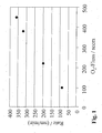
- Fig. 1 is a comparison between the set Oxygen flux and the measured deposition rate shown.
- the deposition rate of the second inorganic layer can be significantly increased.
- Table 1 shows a selection of examined Process parameters for the second inorganic layer, at which the composite of first and second layer a high Barrier effect results.
- the coating time and deposition rate of the second inorganic layer depending on process and plant parameters and characterization of the barrier improvement of the two-layer composite of first organic and second inorganic layer, directly after the coating and after a stress test (Creep test with 4 vol .-% CO 2 ).
- the barrier improvement factor is Barrier improvement factor, BIF, as the ratio of Permeation of an uncoated substrate relative to the Permeation of a coated substrate defined.
- the data shows that process 1, in which the Oxygen flow 100 sccm, the pulse pause 50 ms and the Lance length is 102 mm, a deposition rate of 86 nm / min is reached.
- the coating time is relatively long at 14 seconds.
- deposition rates of processes 2, 3 and 4 with 200, 318 and 360 nm / min due to higher oxygen fluxes of 220, 380 or 450 sccm and shortened to 40 ms Pulse break, as well as the improved lance length of 50 mm significantly higher.
- the thickness of the second layer has been reduced. Overall, this is the resulting coating time to values of 2 to 6 seconds reduced.
- the coating can be used to produce a bonding agent barrier composite with a high oxygen barrier improvement factor (O 2 -BIF), which has a value of significantly> 40 for processes 1, 2 and 3.
- O 2 -BIF oxygen barrier improvement factor
- the permeation of an uncoated bottle is 0.1955 cm 3 / (pack day bar).
- the permeation of the coated bottle is so low that the dissolution limit of the Mocon-Oxtran measuring device used has been reached.
- an O 2 -BIF of 30 is determined.
- the coated bottles are filled for the creep test with 0.4 1 carbonated liquid with a CO 2 content of 4% and sealed with a plastic cap. Subsequently, the filled bottles are first stored at room temperature for 24 hours and then at 38 ° C. for 24 hours.
- the test procedure produces an internal pressure in the bottle of up to 5 bar, whereby the layer / substrate composite um locally more than 4.5% stretched and even plastically deformed becomes. Due to the high strains and / or plastic Deformations, the barrier improvement is reduced, resulting in Changes in the stratification in areas extremely strong Stretching is due.
- the composite is so stable that one distinct detectable barrier effect despite this high load preserved.
- This effect is due to that despite the high elongation and / or plastic deformation no delamination due to good adhesion, and for much of the surface of the coated Substrate no cracking formed in the composite layer, through the barrier effect is worsened.
- the fastest process has a slightly reduced, but always still very high barrier improvement after coating and just as good barrier improvement after the creep test like the slower process 1.
- HOT-FILL-vials This is as usual a Hndbehellbare Bottle, which when filled with a Liquid of a temperature between 85 ° C and 95 ° C in essentially no resizing shows.
- An uncoated HOT-FILL bottle has an oxygen permeation of 0.192 cm 3 / (pack day bar), one. coated bottles have an oxygen permeation below the detection limit of 0.04 cm 3 / (pack day bar) and thus an O 2 -BIF of more than 40.
- coated bottles are first one hour at 35 ° C and 95% relative humidity stored. Then the bottles are set at 0.5 1 with 95 ° C filled with hot water, the temperature is initially 5 minutes maintained lying and then the filled Container in cold water bath for 20 minutes Room temperature cooled.
- PP polypropylene
- the coating time is 1 s for the first organic layer and 5.6 s for the second inorganic layer.
- the coating can be used to produce a primer barrier composite with a high O 2 barrier improvement factor (O 2 -BIF).
- the layers are very adhesive and stretch-resistant. It is in present case no plasma pretreatment or a Activation of the substrate, such as with a Oxygen plasma could be required.
Landscapes
- Chemical & Material Sciences (AREA)
- Engineering & Computer Science (AREA)
- Organic Chemistry (AREA)
- Chemical Kinetics & Catalysis (AREA)
- Materials Engineering (AREA)
- Mechanical Engineering (AREA)
- Metallurgy (AREA)
- General Chemical & Material Sciences (AREA)
- Inorganic Chemistry (AREA)
- Physics & Mathematics (AREA)
- Plasma & Fusion (AREA)
- Chemical Vapour Deposition (AREA)
- Details Of Rigid Or Semi-Rigid Containers (AREA)
- Laminated Bodies (AREA)
- Physical Vapour Deposition (AREA)
- Application Of Or Painting With Fluid Materials (AREA)
Abstract
Description
Die Erfindung betrifft ein schnelles Verfahren zum Aufbringen von Wechselschichten mittels chemischer Gasphasenabscheidungsverfahren, Chemical Vapor Deposition, CVD, insbesondere mittels plasmaunterstützter chemischer Gasphasenabscheidungsverfahren PECVD, Plasma Enhanced Chemical Vapor Deposition, insbesondere gepulster Plasmaunterstützter chemischer Gasphasenabscheidung PICVD, Plasma Impulse Chemical Vapor Deposition, sowie Beschichtungen, welche nach diesem Verfahren aufgebracht werden können.The invention relates to a rapid method of application of alternating layers by means of chemical Vapor Deposition Process, Chemical Vapor Deposition, CVD, in particular by means of plasma-assisted chemical Vapor Deposition Process PECVD, Plasma Enhanced Chemical vapor deposition, in particular pulsed plasma assisted chemical vapor deposition PICVD, plasma Impulse Chemical Vapor Deposition, as well as coatings, which can be applied by this method.
Um die Durchlässigkeit von Verpackungen für Gase und Flüssigkeiten herabsetzen zu können, sowie das Verpackungsmaterial gegen chemische Angriffe oder UV-Strahlung zu schützen, ist es vorteilhaft, diese Verpackungen mit einer Barrierebeschichtung zu versehen. Hierbei ist beispielsweise das Abscheiden dünner SiOx-Beschichtungen oder -Beschichtungssysteme auf Polymersubstraten insbesondere für Massenkunststoffe interessant, um deren Durchlässigkeit vor allem für Sauerstoff und Wasserdampf zu reduzieren und insbesondere dabei gleichzeitig die Transparenz des Materials zu erhalten. Zudem kann der Inhalt derart beschichteter Materialien in der Regel sicher mittels Mikrowellen verwendenden Einrichtungen erwärmt werden. Ein weiterer Vorteil dieser Beschichtungen liegt in der Vielzahl der Möglichkeiten, diese auf Polymeroberflächen abzuscheiden.In order to reduce the permeability of packaging for gases and liquids, as well as to protect the packaging material against chemical attack or UV radiation, it is advantageous to provide these packages with a barrier coating. In this case, for example, the deposition of thin SiO x coatings or coating systems on polymer substrates is of particular interest for bulk plastics, in order to reduce their permeability, especially for oxygen and water vapor, and in particular to obtain the transparency of the material at the same time. In addition, the contents of materials coated in this way can generally be heated reliably using devices using microwaves. Another advantage of these coatings lies in the large number of options for depositing them on polymer surfaces.
Um die Qualität derartiger Beschichtungen zu verbessern, ist es jedoch nötig, den Zusammenhang zwischen der Barrierewirkung, den morphologischen Eigenschaften und dem molekularen Transports durch die Schicht zu kennen und insbesondere den Einfluss der Abscheidungsbedingungen auf die sich ergebenden Beschichtungsparameter zu beherrschen.To improve the quality of such coatings is However, it is necessary to clarify the relationship between the Barrier effect, the morphological properties and the to know molecular transport through the layer and in particular the influence of the deposition conditions on the to master the resulting coating parameters.
In Erlat et al., J. Mater. Res., (2000) 15 S. 704 bis 716 wird eine Modellvorstellung des Zusammenhangs der Barrierewirkung mit der Schichtmorphologie vorgestellt und der Einfluss verschiedener Prozessparameter beleuchtet.In Erlat et al., J. Mater. Res., (2000) 15 pp. 704 to 716 becomes a model of the context of the Barrier effect with the layer morphology presented and the influence of different process parameters is highlighted.
In Erlat et al., J. Phys. Chem. B (1999) 103, S. 6047 bis 6055 wird die Morphologie der Schichten im Hinblick auf glatte Oberflächen im Hinblick auf Prozessparameter beschrieben. Dabei werden in den beiden zuletzt genannten Zitaten aber nur einzelne anorganische Barriereschichten betrachtet.In Erlat et al., J. Phys. Chem. B (1999) 103, p. 6047 until 6055, the morphology of the layers in terms of smooth surfaces with regard to process parameters described. In the latter two are mentioned Quotations but only single inorganic barrier layers considered.
Um die Haftungseigenschaften von SiOx-Schichten auf Polymersubstraten zu verbessern, wird in Rupertus et al., Fresenius J. Anal. Chem. (1997) 358, S. 85 bis 88, eine Vorbehandlung des Substrats in einem Sauerstoffplasma vorgeschlagen.In order to improve the adhesion properties of SiO x layers on polymer substrates, Rupertus et al., Fresenius J. Anal. Chem. (1997) 358, pp. 85-88, proposes a pretreatment of the substrate in an oxygen plasma.
Eine Verbesserung des Beschichtungsprozesses wird in herkömmlicher Weise anhand der Prozessparameter Leistung, Druck und Zeit vorgenommen.An improvement of the coating process is in conventionally based on the process parameters performance, Pressure and time made.
Durch anfängliches Vermeiden von Sauerstoff für die 1. By initially avoiding oxygen for the 1.
Schicht kann nach US-5, 718, 967 A1 eine Haftvermittlerschicht unter Abwesenheit von Sauerstoff und durch anschließendes Einbringen von Sauerstoff darauf eine Schutzschicht unter Sauerstoffüberschuss hergestellt werden.Layer can according to US-5, 718, 967 A1 an adhesive layer in the absence of oxygen and by subsequent Applying oxygen to a protective layer below Oxygen excess can be produced.
Ein Verfahren zur Multilayer-Beschichtung von Kunststoff mit Wechselschichten, die aus HMDSO und TiCl4 hergestellt werden, wird in EP 709485 beschrieben. Dabei werden durch HMDSO organische und durch TiCl4 anorganische Barriereschichten abgeschieden. Es wird in dieser Anmeldung jedoch nicht beschrieben, wie schnelle Prozesszeiten erreicht werden können und wie der schnelle Prozess für Behälter mit einem größeren Volumen > 18ml, typischerweise > 50ml realisiert werden kann.A process for multi-layer coating of plastic with alternating layers made of HMDSO and TiCl 4 is described in EP 709485. HMDSO separates organic and TiCl 4 inorganic barrier layers. However, this application does not describe how fast process times can be achieved and how the fast process can be realized for containers with a larger volume> 18 ml, typically> 50 ml.
Für eine wirtschaftlich Umsetzung eines
Barrierebeschichtungsprozesses auf Substrate, wie z.B. PET-Flaschen,
ist es notwendig, sehr hohe Probendurchsätze zu
realisieren. Typische Probendurchsätze bei Linien, welche
Streckblasmaschinen für Kunststoffbehälter und
nachgeschaltete Abfüllanlagen umfassen, liegen bei 10 000 bis
30 000 Behältern pro Stunde. Für eine optimale Integration
einer in dieser Linie angeordneten
Barrierebeschichtungsanlage in der Reihenfolge
Der Probendurchsatz hängt ferner von der Anzahl der auf einer Beschichtungsmaschine benötigten Stationen ab, so dass durch sehr kurze Beschichtungszeiten die Zahl der benötigten Stationen reduziert bzw. umgekehrt bei gleicher Anzahl der Stationen der Probendurchsatz erhöht werden kann, wodurch sich deutliche Kostenvorteile ergeben.The sample throughput also depends on the number of on one Coating machine needed stations, so that through very short coating times the number of needed Stations reduced or vice versa for the same number of Stations of the sample throughput can be increased, thereby There are significant cost advantages.
In WO 99/49991 wird eine Barrierebeschichtung mit amorphem Kohlenstoff beschrieben, bei welcher ein schnelles Verfahren mit Beschichtungszeiten im Bereich von 2 bis 3 s erreicht wird. Dort wird jedoch nicht angegeben, welche Permeation bzw. Barriereverbesserung gegenüber dem unbeschichteten Substrat bei vorgegebener Prozesszeit erreicht wird. Diese Schichten sind jedoch nicht transparent, vielmehr besitzen diese eine bräunliche bis gelbe Färbung. Gerade bei transparenten zu beschichtenden Behältern wirkt diese Färbung jedoch sehr unästhetisch und führt oft zu nicht akzeptablen Ergebnissen. Falls diese Schichten dünn aufgebracht werden, ist die Färbung zwar geringer, jedoch immer noch vorhanden. Wenn die Schichtdicke reduziert wird, ist jedoch hierdurch die Barrierewirkung signifikant verschlechtert. Ferner können diese Schichten aus amorphem Kohlenstoff nur sehr schwierig und aufwendig vom PET-Substrat entfernt werden. Aus diesem Grund ist das Recycling der beschichteten Behälter problematisch, weil selbst bei einer Mischung mit unbeschichtetem PET noch ein Farbstich im recycelten Produkt zurückbleiben kann. WO 99/49991 discloses a barrier coating with amorphous Carbon described in which a fast process achieved with coating times in the range of 2 to 3 s becomes. However, it does not specify which permeation or barrier improvement over the uncoated Substrate is achieved at a given process time. These However, layers are not transparent, rather possess this is a brownish to yellow color. Especially at transparent to be coated containers this coloring acts but very unaesthetic and often leads to unacceptable Results. If these layers are applied thinly, although the color is lower, it is still present. However, when the layer thickness is reduced, this is the barrier effect worsened significantly. Furthermore, can these layers of amorphous carbon are very difficult and consuming to be removed from the PET substrate. For this The reason is the recycling of the coated containers problematic because even with a mix with uncoated PET another color cast in the recycled product can stay behind.
Beschichtungszeiten von 2 bis 4 s für eine SiOx-Barriereschicht werden auch in den Patentschriften WO 02/09891 A1 und WO 02/10473 beschrieben. Es wird in diesen Veröffentlichungen jedoch nicht angegeben, durch welche Prozessparameter die angegebenen Beschichtungszeiten eingestellt werden können. Es fehlen insbesondere genaue Angaben zu Druck, Konzentration, Mikrowellenleistung und Precursor- sowie zu den Träger- und Reaktivgasflüssen.Coating times of 2 to 4 s for a SiO x barrier layer are also described in the patents WO 02/09891 A1 and WO 02/10473. However, these publications do not specify by which process parameters the stated coating times can be set. Specifically, there is a lack of precise information on pressure, concentration, microwave power and precursor as well as the carrier and reactive gas flows.
In der W02/10473 wird außerdem ein Verfahren beschrieben, beim dem Schichten aus verschiedenen Ausgangsverbindungen aufgebracht werden, bestehend aus einer Schutzschicht aus amorphem Kohlenstoff, einer SiOx-Schicht und einer Grenzschicht zum Substrat hergestellt aus Sauerstoff und einer "Organo-Silzium-haltigen" Verbindung. Dieses Verfahren ist sehr aufwendig, da insgesamt 3 Schichten aufgebracht werden und stark unterschiedliche Ausgangsverbindungen verwendet werden müssen. Auch in Anspruch 1-10 der WO 02/09891 A1 wird ein ähnlich aufwendiges Verfahren beschrieben.W02 / 10473 also describes a method when layering from different starting compounds be applied, consisting of a protective layer amorphous carbon, a SiOx layer and a Boundary layer to the substrate made of oxygen and an "organo-silicon-containing" compound. This method is very elaborate, because a total of 3 layers applied and strongly different starting compounds must be used. Also in claim 1-10 of WO 02/09891 A1 becomes a similarly complicated process described.
Ausgehend von den vorstehend beschriebenen bekannten Verfahren liegt eine Aufgabe der Erfindung darin, ein möglichst optimal in eine Produktionslinie integrierbares Verfahren zum Aufbringen qualitativ hochwertiger Barriereschichten auf ein Substrat, wie beispielsweise auf die innere Oberfläche einer Kunststoffflasche, zur Verfügung zu stellen.Starting from the known ones described above Method is an object of the invention therein, a as optimally as possible integrated into a production line Method of applying high quality Barrier layers on a substrate, such as on the inner surface of a plastic bottle, available to deliver.
Gelöst wird diese Aufgabe auf überraschend einfach Weise bereits durch die Merkmale des Anspruchs 1. Ferner ist in Anspruch 33 ein Verbundmaterial angegeben, welches mit dem erfindungsgemäßen Verfahren herstellbar ist.This task is solved in a surprisingly simple way already by the features of claim 1. Further, in Claim 33, a composite material specified, which with the inventive method can be produced.
Vorteilhafte Weiterbildungen finden sich jeweils in den zugeordneten Unteransprüchen.Advantageous developments can be found in each of the associated subclaims.
Bereits in der Anmeldung PCT/EP/02 08 853 mit dem Titel "Verbundmaterial aus einem Substratmaterial und einem Barriereschichtmaterial" hat der Anmelder ein Verfahren zur Herstellung eines Verbundmaterials mit einer verbesserten Barrierewirkung und einer verbesserten Haftung vorgeschlagen. Auf diese Anmeldung PCT/EP/02 08 853 wird Bezug genommen und deren Inhalt vollumfänglich in die vorliegende Anmeldung sowie in ein sich später hieraus ergebendes Schutzrecht durch Bezugnahme mit aufgenommen.Already in the application PCT / EP / 02 08 853 entitled "Composite material of a substrate material and a Barrier Layer Material ", the Applicant has developed a method for Production of a composite material with an improved Barrier effect and improved adhesion proposed. This application PCT / EP / 02 08 853 is referred to and their contents in full in the present application as well as in a subsequently resulting property right by Reference included.
Bei dem erfindungsgemäßen Verfahren werden Wechselschichten allein aus einem Precursormaterial oder aus 2 Silizium haltigen Precursormaterialien hergestellt. Dadurch ist eine schnelle und einfach zu realisierende Prozessführung möglich, welche auch insbesondere die im Anspruch 1 angegebenen schnellen Prozesszeiten ermöglicht.In the method according to the invention are alternating layers solely from a precursor material or from 2 silicon containing precursor materials produced. This is one fast and easy to implement process control possible, which also specified in particular in claim 1 fast process times possible.
Ein Übergang zwischen organischen und anorganischen Schichten kann variabel gestaltet werden, und es lassen sich zudem sehr glatte Schichten aufbringen, wobei durch die Grenzflächen zwischen organischen und anorganischen Schichten eine Verstärkung der Barrierewirkung erreicht wird.A transition between organic and inorganic layers can be made variable, and it can also be very apply smooth layers, passing through the interfaces between organic and inorganic layers one Reinforcement of the barrier effect is achieved.
Die Erfindung sieht vor, den Gesamtfluss für die zweite anorganische Schicht gegenüber dem Gesamtfluss für die erste organische Haftvermittlerschicht gleich groß zu lassen oder zu erhöhen. Vorteilhafterweise kann damit für den zuletzt genannten Fall die Abscheiderate für die zweite Schicht deutlich gesteigert werden, so dass die gesamte Beschichtungszeit nochmals reduziert werden kann. Durch eine Erhöhung des Gesamtflusses kann bei niedriger Precursorkonzentration die Qualität der Barriereschicht beibehalten und gleichzeitig die Abscheiderate deutlich gesteigert werden, so dass für die zweite anorganische Barriereschicht bei gleicher Schichtdicke eine deutlich reduzierte Beschichtungszeit ermöglicht wird.The invention provides, the total flow for the second inorganic layer versus the total flux for the first to leave organic adhesion promoter layer the same size or to increase. Advantageously, it can be used for the last In the case mentioned, the deposition rate for the second layer be increased significantly, so that the entire Coating time can be reduced again. By a Increase in total flow can be at lower Precursor concentration the quality of the barrier layer maintain and at the same time the deposition rate significantly be increased, so that for the second inorganic Barrier layer at the same layer thickness one clearly reduced coating time is possible.
Die erfindungsgemäße Lösung stellt damit erstmals ein Verfahren zum Aufbringen von Wechselschichten, das heißt von mindestens 2 Schichten, durch CVD-, bevorzugt PECVD-, insbesondere PICVD-Verfahren zur Verfügung, welches die Verfahrensschritte des schnellen Abscheidens einer Haftvermittlerschicht auf einem Substrat und des Aufbringens einer Sperrschicht umfasst, wobei alternierend Wechselschichten aus organischen und anorganischen Materialien abgeschieden werden. Vorzugsweise werden nur 2 Schichten abgeschieden. Damit können besonders schnelle Prozesszeiten realisiert werden.The solution according to the invention thus sets for the first time Process for applying alternating layers, that is from at least 2 layers, by CVD, preferably PECVD, in particular PICVD method available which the Process steps of the rapid deposition of a Adhesive layer on a substrate and the application a barrier layer, wherein alternately Alternating layers of organic and inorganic Materials are deposited. Preferably, only 2 Layers deposited. This can be very fast Process times are realized.
Die Wechselschichten können vorteilhafterweise aus nur einem einzigen Precursorgas oder 2 ähnlichen siliziumhaltigen organischen Precursorgasen abgeschieden werden, wie beispielsweise Hexamethyldisiloxan oder Hexamethyldisilazan für beide Schichten oder Hexamethyldisiloxan für die erste organische und Hexamethyldisilazan für die zweite anorganische Schicht.The alternating layers may advantageously consist of only one single Precursorgas or 2 similar silicon-containing organic precursor gases are deposited, such as for example, hexamethyldisiloxane or hexamethyldisilazane for both layers or hexamethyldisiloxane for the first organic and hexamethyldisilazane for the second inorganic layer.
Das Verfahren ist dadurch gekennzeichnet, dass die Beschichtungszeit zum Aufbringen der Haftvermittlerschicht zwischen 0,05 s und 4 s liegt, und/oder die Beschichtungszeit zum Aufbringen der Sperrschicht zwischen 0,1 s und 6 s liegt. The method is characterized in that the Coating time for applying the adhesion promoter layer between 0.05 s and 4 s, and / or the coating time for applying the barrier layer between 0.1 s and 6 s.
Mit "Beschichtungszeit" ist dabei die Zeitdauer gemeint, in der eine Schicht auf dem Substrat abgeschieden wird und während der ein kontinuierliches oder ein gepulstes Plasma brennt.By "coating time" is meant the duration, in the one layer is deposited on the substrate and while a continuous or a pulsed plasma burning.
Für eine effiziente Herstellung von Sperrschichten, insbesondere auf dielektrischen Materialien, ist es notwendig, glatte Schichten mit einer geringen Dichte an inneren Grenzflächen oder anderen Inhomogenitäten abzuscheiden. Eine hohe Dichte an topologischen oder chemischen Inhomogenitäten kann zu einer erhöhten Durchlässigkeit der Schicht führen.For efficient production of barrier layers, especially on dielectric materials, it is necessary, smooth layers with a low density internal interfaces or other inhomogeneities deposit. A high density of topological or chemical inhomogeneities can be increased Permeability of the layer lead.
Dies ist vor allem dann der Fall, wenn kurze Diffusionspfade entlang der Inhomogenitäten vorhanden sind, durch die im Vergleich zum Volumen eine schnelle Diffusion ablaufen kann. Zum Beispiel lässt sich in der Regel mit sehr porösen Schichten keine gute Barrierewirkung erzielen. Bevorzugt sind daher Schichten mit einer geringen Dichte an kurzen Diffusionswegen, wie zum Beispiel amorphe Schichten mit einer niedrigen Dichte an inneren Grenzflächen bzw. polykristalline Schichten mit einer niedrigen Dichte an Korngrenzen.This is especially the case when short diffusion paths along the inhomogeneities are present, through which in the Compared to the volume a fast diffusion can proceed. For example, it is usually very porous Layers do not achieve a good barrier effect. Preferred are therefore layers with a low density of short Diffusion paths, such as amorphous layers with a low density of internal interfaces or polycrystalline Layers with a low density of grain boundaries.
Die Diffusion durch die Grenzflächen zwischen organischen und anorganischen Schichten wird bei Wechselschichten deutlich gehemmt bzw. der Diffusionsweg wird deutlich verlängert.The diffusion through the interfaces between organic and inorganic layers becomes apparent in alternating layers inhibited or the diffusion path is significantly extended.
Durch geeignet gewählte Prozessparameter können sowohl sehr glatte anorganische als auch sehr glatte organische Schichten abgeschieden werden. In der am selben Tag von der Anmelderin eingereichten Anmeldung mit dem Titel "Verfahren zum Herstellen von glatten Barriereschichten und Verbundmaterial mit glatter Barriereschicht" mit dem Aktenzeichen der Anmelderin 02SGL0184DEP (Anmeldenummer wird nach Erhalt des amtlichen Aktenzeichens nachgetragen) schlägt der Anmelder eine Vorrichtung und ein Verfahren zum Herstellen sehr glatter Barrierewechselschichten vor. Auf diese Anmeldung wird hier vollumfänglich Bezug genommen.By suitably selected process parameters can be both very smooth inorganic as well as very smooth organic layers be deposited. In the same day by the applicant filed application entitled "Procedure for Producing smooth barrier layers and composite material with smooth barrier layer "with the file number of Applicant 02SGL0184DEP (Application number will be sent after receipt of the the official file number), the applicant proposes a device and a method of manufacturing very smooth barrier layer changes. On this application is fully incorporated herein by reference.
Um den erfindungsgemäß sehr schnellen Prozess auf einfache Weise realisieren zu können, werden die erfindungsgemäßen Wechselschichten durch Variation von zumindest einem Prozessparameter abgeschieden.To the inventively very fast process to simple To be able to realize manner, the invention Alternating layers by variation of at least one Process parameters deposited.
Die Erfinder haben herausgefunden, dass durch den Einsatz eines plasmaunterstützen CVD-Verfahrens, eines sogenannten PICVD-Verfahrens, besonders gut haftende Schichten mit einer hervorragenden Barrierewirkung in einer sehr kurzen Prozesszeit abgeschieden werden können. Mit Hilfe der PICVD-Technik können sehr dünne Schichten auf ein Substratmaterial aufgebracht werden, die dennoch sehr gute Barriereeigenschaften aufweisen. Die Schichten haben zudem eine hohe Flexibilität.The inventors have found that through use a plasma assisted CVD process, a so-called PICVD process, particularly well-adherent layers with a excellent barrier effect in a very short time Process time can be deposited. Using the PICVD technique can be very thin layers on a substrate material be applied, yet very good Have barrier properties. The layers also have a high flexibility.
Die Verwendung eines PICVD- Verfahrens ermöglicht des Weiteren den Einsatz auf Mehrplatzanlagen, was insbesondere einen hohen Durchsatz ermöglicht.The use of a PICVD method allows the Furthermore, the use of multi-user systems, in particular allows a high throughput.
Vorteilhaft wird bei dem erfindungsgemäßen Verfahren beim Abscheiden der Schichten ein mittels Mikrowellen erzeugtes Plasma eingesetzt. Vorzugsweise finden dabei Mikrowellen einer Frequenz von 2,45 GHz Verwendung. Zudem ist vorgesehen, dass das mittels Mikrowellen erzeugte Plasma gepulst wird.The advantage of the method according to the invention in Depositing the layers by means of microwaves Plasma used. Preferably, find microwaves a frequency of 2.45 GHz use. It is also planned that the plasma generated by microwaves is pulsed.
Durch einen erhöhten Gesamtfluss ändert sich das Strömungsprofil im Behälter. Es zeigte sich, dass abhängig vom Gasfluss insbesondere für die anorganische Barriereschicht die Lanzenlänge, mittels welcher das Precursorgas in den zu beschichtenden Behälter eingebracht wurde, vorteilhaft angepasst werden kann, um in dem Behälter eine gleichmäßige Verteilung der Komponenten im Prozessgas realisieren zu können. Die Lanzenlänge ist dabei definiert als der Abstand zwischen der Öffnung, aus der Gas in den zu beschichtenden Behälter strömt und der Außenkante der Behälteröffnung des zu beschichtenden Behälters, welche gegen die Atmosphäre abgedichtet wird. Bei dieser Anpassung wird die Schichtdickenverteilung für die organische Schicht nur geringfügig geändert.This is changed by an increased total flow Flow profile in the container. It turned out that dependent from the gas flow especially for the inorganic Barrier layer the lance length, by means of which the Precursorgas introduced into the container to be coated has been, can be advantageously adapted to be in the container a uniform distribution of the components in the process gas to be able to realize. The lance length is defined as the distance between the opening, from the gas in the too Coating container flows and the outer edge of the Container opening of the container to be coated, which against the atmosphere is sealed. This adjustment will the layer thickness distribution for the organic layer only slightly changed.
Neben der Lanzenlänge sieht die Erfindung vor, auch die Pulspause an einen erhöhten Gesamtfluss anzupassen. Dabei wird bei höherem Gesamtfluss die Pulspause verkürzt.In addition to the lance length, the invention provides, including the Pulse break to adapt to increased overall flow. there the pulse pause is shortened with higher total flow.
Die Pulspause bestimmt die Zeitdauer, in der frisches Prozessgas in den Behälter einströmen kann, bevor ein Plasma gezündet wird und die Beschichtung erfolgt. Bei optimierter Strömung im Hinblick auf den Druck, den Gesamtfluss, die Precursorkonzentration, die Lanzenlänge sowie den Düsendurchmesser kann eine gute Verteilung der Komponenten des Prozessgases bereits bei kürzeren Pulspausen erreicht und somit der Verfahrensablauf nochmals beschleunigt werden.The pulse break determines the length of time in which fresh Process gas can flow into the container before a plasma is ignited and the coating takes place. At optimized Flow in terms of pressure, the total flow, the Precursor concentration, the lance length and the Nozzle diameter can be a good distribution of the components the process gas already reached at shorter pulse pauses and Thus, the procedure can be accelerated again.
Es ist zu beachten, dass die Abscheiderate bei gepulsten Plasmen nicht zwingend niedriger als bei sogenannten "Continuous Wave-Plasmen (CW-Plasmen)" sein muss, weil bei geeignet bestimmten Parametern beim gepulsten Plasma innerhalb der Pulsdauer eine nahezu vollständige Stoffumsetzung stattfinden kann und innerhalb der Pulspause neues Frischgas einströmt, das beim nächsten Puls wieder nahezu vollständig umgesetzt wird.It should be noted that the deposition rate at pulsed Plasmas are not necessarily lower than in so-called "Continuous wave plasmas (CW plasmas)" must be because at suitable for certain parameters in the pulsed plasma within the pulse duration an almost complete Substance conversion can take place and within the pulse break new fresh gas flows in, the next pulse again almost completely implemented.
Die Abscheiderate bei gepulsten Plasmen kann sogar höher sein, wenn das frische Prozessgas zeitgerecht einströmt und dann während des Pulses mit hoher Pulsleistung eine höhere Stoffmengenumsetzung stattfindet als bei einem CW-Plasma mit niedrigerer Momentanleistung. Mit kürzerer Pulspause nimmt die Abscheiderate bis zu einem Optimum deutlich zu, da der Anteil an umgesetztem Precursorgas bis zur Sättigung steigt.The rate of deposition in pulsed plasmas can be even higher be when the fresh process gas flows in time and then during the pulse with high pulse power a higher Substance conversion takes place as in a CW plasma lower instantaneous power. With a shorter pulse break takes the deposition rate up to an optimum, since the Proportion of reacted precursor gas increases to saturation.
Erfindungsgemäß liegt die Abscheiderate für die organische Schicht im Bereich von 120 nm/min bis 5000 nm/min, vorzugsweise im Bereich von 500 nm/min bis 2000 nm/min, und/oder für die anorganische Schicht im Bereich von 60 nm/min bis 2000 nm/min, vorzugsweise im Bereich von 100 nm/min bis 1000 nm/min.According to the invention, the deposition rate for the organic Layer in the range from 120 nm / min to 5000 nm / min, preferably in the range from 500 nm / min to 2000 nm / min, and / or for the inorganic layer in the range of 60 nm / min to 2000 nm / min, preferably in the range of 100 nm / min to 1000 nm / min.
Folglich kann durch Verkürzung der Pulspause eine deutlich niedrigere Beschichtungszeit erreicht werden, wobei sich ein Optimum ausbildet, denn bei zu kurzer Pulspause wird die Uniformität der Beschichtung zu schlecht, weil sich keine gleichmäßige Verteilung der Komponenten des Prozessgases ausbilden kann.Consequently, by shortening the pulse pause a clear lower coating time can be achieved, with a Optimum training, because too short a pause in the pulse is the Uniformity of the coating too bad, because no uniform distribution of the components of the process gas can train.
Die Uniformität ist definiert als das Verhältnis der minimalen Schichtdicke zur maximalen Schichtdicke, wobei die Werte durch Messung über das genannte Substrat ermittelt werden.Uniformity is defined as the ratio of minimum layer thickness to the maximum layer thickness, wherein the Values determined by measurement over said substrate become.
Bei zu langer Pulspause steigt hingegen der Anteil an unverbrauchtem Prozessgas an. Mit zunehmendem Gesamtfluss wird erfindungsgemäß die Lanzenlänge reduziert. Die Lanzenlänge liegt bei Werten im Bereich von 5 % bis 80 %, vorzugsweise im Bereich von 10 % bis 50 % der Höhe eines zu beschichtenden Hohlkörpers.If the pulse break is too long, however, the proportion increases Unused process gas. With increasing total flow According to the invention, the lance length is reduced. The Lance length is in the range of 5% to 80%, preferably in the range of 10% to 50% of the height of one coating hollow body.
Ein weiterer Vorteil des gepulsten Plasmas ist, dass sehr reine anorganische Barriereschichten hergestellt werden können, weil im Gegensatz zum CW-Plasma unerwünschte organische Reaktionsprodukte in der Pulspause entfernt werden können und somit ein deutlich geringerer Anteil an organischen Bestandteilen in den Schichten eingebaut wird.Another advantage of the pulsed plasma is that very pure inorganic barrier layers are produced can, because unlike the CW plasma undesirable organic reaction products are removed during the pulse break can and therefore a significantly lower proportion of organic components is incorporated in the layers.
Zusätzlich zu den vorstehend genannten Vorteilen des PICVD-Verfahrens wird damit die Möglichkeit geschaffen, für das schnelle Abscheiden von Wechselschichten aus einem einzigen Precursorgas oder 2 ähnlichen siliziumhaltigen Precursorverbindungen weitere Prozessparameter zur Steuerung des Verfahrens zur Verfügung zu stellen.In addition to the aforementioned advantages of the PICVD process This creates the opportunity for the rapid deposition of alternating layers from a single Precursorgas or 2 similar silicon-containing Precursor compounds further process parameters for control to provide the method.
Der zumindest eine zu variierende Prozessparameter wird aus der Gruppe ausgewählt, die die Precursorkonzentration, die mittlere Mikrowellenleistung, den Druck, die Pulsleistung, die Pulsdauer, die Dauer der Pulspause und den Gesamtfluss umfasst. Diese Parameter bieten die Möglichkeit bei sehr kurzer Beschichtungszeit dennoch qualitativ hochwertige Barriereschichten abzuscheiden. Alle genannten Prozessparameter beziehen sich auf die Beschichtung von einem einzelnen Substrat. Für die Beschichtung von vielen Substraten in einer Mehrplatzanlage, beispielsweise einer Rundläufer- oder Batch-Anlage mit mehreren Kammern, beziehen sich die genannten Parameter jeweils auf die Beschichtung in einer einzelnen Kammer.The at least one process parameter to be varied becomes the group selected, the precursor concentration, the mean microwave power, the pressure, the pulse power, the pulse duration, the duration of the pulse break and the total flow includes. These parameters offer the possibility at very short coating time yet high quality To separate barrier layers. All mentioned Process parameters refer to the coating of one single substrate. For the coating of many Substrates in a multi-user system, for example one Rotary or batch system with several chambers, relate the parameters mentioned in each case on the coating in a single chamber.
Als optimale Pulspausen ergaben sich für die organische Schicht Werte im Bereich von 2 ms bis 100 ms, vorzugsweise zwischen 5 ms und 60 ms, und für die anorganische Schicht zwischen 5 ms und 200 ms, vorzugsweise 20 ms und 50 ms.Optimal pulse pauses resulted for the organic Layer values in the range of 2 ms to 100 ms, preferably between 5 ms and 60 ms, and for the inorganic layer between 5 ms and 200 ms, preferably 20 ms and 50 ms.
Erfindungsgemäß werden dafür die Parameter auf optimale Werte eingestellt.According to the invention, the parameters for optimal values set.
Insbesondere ist vorgesehen, dass die Precursorkonzentration zum Aufbringen der ersten organischen Haftvermittlerschicht im Bereich 5 % bis 80 % des Gesamtflusses liegt und/oder dass die Precursorkonzentration zum Aufbringen der zweiten anorganischen Barriereschicht im Bereich von 0,5 % bis 4 % vorzugsweise zwischen 0,8 % und 3 % des Gesamtflusses liegt.In particular, it is provided that the precursor concentration for applying the first organic adhesion promoter layer in the range 5% to 80% of the total flow and / or that the precursor concentration for applying the second inorganic barrier layer in the range of 0.5% to 4% preferably between 0.8% and 3% of the total flux.
Des Weiteren ist vorgesehen, dass die Pulsleistung für die organische Schicht im Bereich von 100 W bis 5000 W, vorzugsweise im Bereich von 400 W und 1500 W, liegt, und/oder dass die Pulsleistung für die zweite anorganische Schicht im Bereich von 100 W bis 5000 W, vorzugsweise im Bereich von 400 W bis 1500 W liegt.Furthermore, it is provided that the pulse power for the organic layer in the range of 100 W to 5000 W, preferably in the range of 400 W and 1500 W, and / or that the pulse power for the second inorganic layer in the Range of 100 W to 5000 W, preferably in the range of 400 W to 1500 W is.
Die mittlere Mikrowellenleistung liegt erfindungsgemäß für die organische Schicht im Bereich von 10 W und 5000 W, vorzugsweise im Bereich von 10 W und 500 W, und/oder für die anorganische Schicht im Bereich von 10 W bis 5000 W, vorzugsweise im Bereich von 30 W und 2000 W.The mean microwave power is according to the invention for the organic layer in the range of 10 W and 5000 W, preferably in the range of 10 W and 500 W, and / or for the inorganic layer in the range of 10 W to 5000 W, preferably in the range of 30 W and 2000 W.
Die Barrierebeschichtung kann auch besonders vorteilhaft eine senkrecht zur beschichteten Oberfläche des Substrats variierende Zusammensetzung oder Struktur aufweisen. Die Variation kann dabei stetig oder stufenweise sein.The barrier coating can also be particularly advantageous perpendicular to the coated surface of the substrate have varying composition or structure. The Variation can be steady or gradual.
Eine stufenweise Variation ergibt eine mehrschichtige Barrierebeschichtung. Beispielsweise kann die unterste Schicht, die mit der Oberfläche des Substrats in Kontakt ist, als Haftvermittlerschicht für die darauffolgenden Beschichtungen dienen. Solche Schichten oder Schichtsysteme können zum Beispiel durch kontinuierliche oder stufenweise Änderung der Precursorkonzentration während der Beschichtung hergestellt werden.A stepwise variation gives a multilayered Barrier coating. For example, the lowest Layer which is in contact with the surface of the substrate, as a primer layer for the following Coatings serve. Such layers or layer systems For example, by continuous or gradual Change in precursor concentration during coating getting produced.
Besonders gute Beschichtungseigenschaften lassen sich dabei mit Mehrfachwechselschichten, sogenannten Multilayern, erreichen.Particularly good coating properties can be achieved with multiple layers, so-called multilayers, to reach.
Das zu beschichtende Substratmaterial kann auch insbesondere einen Hohlkörper umfassen. Mit dem erfindungsgemäßen Verfahren kann so eine Beschichtung auf der Innenseite und/oder der Außenseite des Hohlkörpers abgeschieden werden.The substrate material to be coated may also be particularly comprise a hollow body. With the invention Procedure can be such a coating on the inside and / or the outside of the hollow body are deposited.
In der am gleichen Tag beim Deutschen Patent- und Markenamt eingereichten Anmeldung der Anmelderin der vorliegenden Anmeldung mit dem Titel " Verfahren zum Herstellen von glatten Barriereschichten und Verbundmaterial mit glatter Barriereschicht", Aktenzeichen der Anmelderin 02SGL0184DEP, wird eine Vorrichtung zum Aufbringen von Barriereschichten auf Hohlkörper als Substrat beschrieben. Auf die Offenbarung dieser Anmeldung wird hier vollumfänglich Bezug genommen und der Inhalt dieser Anmeldung durch Bezugnahme auch vollumfänglich zu Gegenstand der vorliegenden Anmeldung gemacht.In the same day at the German Patent and Trademark Office filed application of the present applicant Application entitled "Method of Making smooth barrier layers and composite with smoother Barrier layer ", file number of the applicant 02SGL0184DEP, becomes a device for applying barrier layers on hollow body described as a substrate. On the revelation this application is incorporated herein by reference in its entirety and the content of this application by reference also fully to the subject of the present application made.
Die Erfindung sieht ferner vorteilhaft vor, als Substrat einen Hohlkörper, vorzugsweise gleichzeitig, außenseitig auf einen Druck p1 zu evakuieren und innenseitig auf einen Basisdruck p2 < p1 abzupumpen, wobei der Druck p1 insbesondere im Bereich um 50 mbar und der Basisdruck p2 insbesondere unterhalb von 0,1 mbar liegt.The invention further advantageously provides, as substrate, a hollow body, preferably simultaneously, to evacuate on the outside to a pressure p 1 and to pump off the inside to a base pressure p 2 <p 1 , the pressure p 1 in particular in the range around 50 mbar and the base pressure p 2 is in particular below 0.1 mbar.
Des Weiteren ist für das erfindungsgemäße Verfahren vorgesehen, ein den Precursor enthaltendes Gasgemisch bei einem Druck p3 mit p2 < p3 < p1 in den Innenraum des Substrats zu leiten, wobei der Druck p3 insbesondere für die erste organische Schicht im Bereich von 0,1 mbar bis 1,0 mbar, vorzugsweise im Bereich von 0,2 mbar bis 0,5 mbar, und für die zweite anorganische Schicht im Bereich von 0,1 mbar bis 1,0 mbar, vorzugsweise im Bereich von 0,25 mbar bis 0,6 mbar liegt. Damit wird vorteilhafterweise erreicht, dass auf die Wandungen des Hohlkörpers keine zu großen Druckunterschiede wirken, die bei dünnwandigem Material zur Verformung des Hohlkörpers führen könnten.Furthermore, it is provided for the method according to the invention to pass a precursor-containing gas mixture at a pressure p 3 with p 2 <p 3 <p 1 into the interior of the substrate, the pressure p 3 in particular for the first organic layer in the range of 0.1 mbar to 1.0 mbar, preferably in the range of 0.2 mbar to 0.5 mbar, and for the second inorganic layer in the range of 0.1 mbar to 1.0 mbar, preferably in the range of 0.25 mbar to 0.6 mbar. This is advantageously achieved that act on the walls of the hollow body not too large pressure differences, which could lead to deformation of the hollow body with thin-walled material.
Ferner kann es für die ausschließliche Innenbeschichtung vorteilhaft sein, den Außendruck so zu wählen, dass im Außenraum kein Plasma gezündet wird. Um bereits während des Abpumpens große Druckunterschiede zu vermeiden, kann dabei vorteilhaft zunächst gleichmäßig so abgepumpt werden, dass der vorstehend genannte Außendruck erreicht wird und dann anschließend nur innenseitig bis zu einem Basisdruck im angegebenen Bereich abzupumpen.Furthermore, it may be for the exclusive interior coating be advantageous to choose the external pressure so that in Outside no plasma is ignited. To already during the Abpumpens can avoid large pressure differences, thereby Advantageously initially be pumped evenly so that the above-mentioned external pressure is achieved and then then only inside up to a base pressure in Pump out the indicated area.
Bei dem Verfahren ist vorteilhaft der Gesamtfluß und/oder der Druck p3 im Innenraum des Substrats beim Abscheiden der anorganischen Sperrschicht zumindest gleich, insbesondere höher als der Gesamtfluß und/oder der Druck p3 im Innenraum des Substrats beim Abscheiden der organischen Haftvermittlerschicht. Daher kann mit der Erfindung eine deutlich höhere Abscheiderate beim Aufbringen der anorganischen Sperrschicht erreicht werden als bei einem niedrigeren Gesamtfluß. In the method, the total flux and / or the pressure is advantageous p 3 in the interior of the substrate during deposition of the inorganic barrier layer is at least equal, in particular higher than the total flow and / or the pressure p 3 in the interior of the substrate during deposition of the organic adhesive layer. Therefore, with the invention, a significantly higher deposition rate when applying the inorganic barrier layer can be achieved than at a lower total flux.
Das Prozeßgas für eine Schicht wird erfindungsgemäß bei einem Druck p4 eingelassen, welcher höher ist als der Druck p5 unmittelbar vor dem Zünden des Plasmas. So kann der Befüllvorgang schnell und effizient durchgeführt werden. Während des Aufbringens einer Schicht fällt der Prozeßdruck bis zum Beginn des Aufbringens der folgenden Schicht dann kontinuierlich ab, und die Temperatur steigt während des Aufbringens der Beschichtung kontinuierlich.The process gas for a layer is inventively admitted at a pressure p 4 , which is higher than the pressure p 5 immediately before the ignition of the plasma. Thus, the filling process can be performed quickly and efficiently. During the application of a layer, the process pressure then drops continuously until the beginning of the application of the following layer, and the temperature continuously increases during the application of the coating.
Erfindungsgemäß liegt der Gesamtfluss für die organische Haftvermittlerschicht im Bereich von 10 sccm bis 250 sccm, vorzugsweise im Bereich von 40 sccm bis 100 sccm, und für die anorganische Schicht im Bereich von 200 sccm bis 1000 sccm, vorzugsweise im Bereich von 250 sccm bis 400 sccm.According to the invention, the total flux for the organic Adhesive layer in the range of 10 sccm to 250 sccm, preferably in the range of 40 sccm to 100 sccm, and for the inorganic layer in the range of 200 sccm to 1000 sccm, preferably in the range of 250 sccm to 400 sccm.
Das Verfahren zeichnet sich außerdem dadurch aus, dass beim Wechsel der Prozeßparameter beim Übergang zwischen zwei Beschichtungsschritten das Plasma entweder weiter brennt oder für eine Übergangszeit unterbrochen wird. Damit wird durch die Erfindung ein weicher kontinuierlicher Übergang in Form eines Gradienten oder ein harter Übergang in Form einer Stufe ermöglicht und ferner die Möglichkeit zur Energieeinsparung gegeben. Insbesondere ist die Übergangszeit für ein gepulstes Plasma größer als die Pulspause.The method is also characterized by the fact that the Change of process parameters at the transition between two Coating steps, the plasma either continues to burn or is interrupted for a transitional period. This is going through the invention a soft continuous transition in shape a gradient or a hard transition in the form of a step allows and also the possibility for energy saving given. In particular, the transitional period is for a pulsed one Plasma larger than the pulse break.
Das erfindungsgemäße Verfahren macht grundsätzlich eine Vorbehandlung des Substrats überflüssig. Im Fall besonders kritischer Substrate, die beispielsweise aus einem Material bestehen, auf dem die Haftung der Beschichtung nicht zufriedenstellend ist, kann jedoch mit dem Verfahren auch vor dem Aufbringen der Beschichtung eine Plasmavorbehandlung durchgeführt werden. Um dennoch die hohe Geschwindigkeit des erfindungsgemäßen Verfahrens dadurch nicht herabzusetzen, liegt die Dauer der Plasmavorbehandlung unterhalb von 5 s, vorzugsweise unterhalb von 1 s.The inventive method basically makes one Pretreatment of the substrate superfluous. In the case especially critical substrates, for example made of a material insist on which the adhesion of the coating is not is satisfactory, however, with the procedure can also be the application of the coating a plasma pretreatment be performed. Nevertheless, the high speed of the not to degrade the process according to the invention is the duration of the plasma pretreatment below 5 s, preferably below 1 s.
Um die Möglichkeiten zur Prozesssteuerung zu erweitern und synergistische Effekte nutzbar zu machen, ist des Weiteren vorgesehen, eine Kombination von Prozessparametern zu variieren.To expand the possibilities for process control and It is also possible to harness synergistic effects provided a combination of process parameters vary.
Je nach den Anforderungen an die Beschichtung können mit dem erfindungsgemäßen Verfahren Schichten mit unterschiedlichen Eigenschaften hergestellt werden. Zum Beispiel kann eine Vorgabe darin liegen, insbesondere für eine verbesserte Barrierewirkung definierte Grenzflächen in der Beschichtung zu fertigen. Daher umfasst die erfindungsgemäße Lösung verschiedene Möglichkeiten zur Variation der Prozessparameter. Der zumindest eine Prozessparameter kann kontinuierlich oder diskontinuierlich variiert werden, alternativ kann der zumindest eine Prozessparameter teilweise kontinuierlich und/oder teilweise diskontinuierlich variiert werden.Depending on the requirements of the coating can be with the Process according to the invention layers with different Properties are produced. For example, a In it, especially for an improved Barrier effect defined interfaces in the coating to manufacture. Therefore, the solution according to the invention comprises different ways to vary the Process parameters. The at least one process parameter can be varied continuously or discontinuously, Alternatively, the at least one process parameter can partially varies continuously and / or partially discontinuously become.
Bei dem erfindungsgemäßen Verfahren wird vorteilhaft zunächst eine organische Schicht auf dem Substrat als Haftvermittlerschicht abgeschieden. Dadurch wird eine bessere Haftung weiterer Schichten, insbesondere einer Barriereschicht, ermöglicht.In the method according to the invention is advantageous first an organic layer on the substrate as Adhesive layer deposited. This will make a better one Adhesion of further layers, in particular one Barrier layer, allows.
Beim Abscheiden der Haftvermittlerschicht erfolgt eine Fragmentierung des Precursors. Durch geeignete Wahl der Prozessparameter wird die Fragmentierung des Precursors derart beeinflusst, dass einzelne Fragmente in Form von Atomen, Molekülen, Ionen oder Radikalen mit den Molekülen des zu beschichtenden Substrats reagieren und eine chemische Bindung (Chemisorption) eingehen. Diese Bindung wird gegenüber einer Physisorption bevorzugt. Durch die starke Bindung in Folge der Fragmentierung des Precursors wird die Schichthaftung verbessert. Durch die Fragmentierung entsteht insbesondere eine organische Haftvermittlerschicht mit einem Kohlenstoffgehalt von mehr als 10 %.When depositing the adhesion promoter layer is a Fragmentation of the precursor. By a suitable choice of Process parameter is the fragmentation of the precursor influenced so that individual fragments in the form of Atoms, molecules, ions or radicals with the molecules of the react to be coated substrate and a chemical Binding (chemisorption). This bond will preferred over physisorption. By the strong Binding due to the fragmentation of the precursor becomes the Layer adhesion improved. Due to fragmentation arises in particular an organic adhesion promoter layer with a Carbon content of more than 10%.
Durch die Prozessparameter wird das Wachstum der Haftvermittlerschicht weiterhin derart beeinflusst, dass die organische Schicht vorteilhafterweise im Lagenwachstum auf dem Substrat abgeschieden wird und nur wenige Defekte in Form von inneren Grenzflächen aufweist. Die Haftvermittlerschicht ist damit sehr glatt und kann bereits selbst eine Barrierewirkung besitzen, weil sie nur sehr wenige Grenzflächen besitzt, die als Pfade für eine schnelle Diffusion dienen könnten.Through the process parameters, the growth of the Adhesive layer further influenced so that the organic layer advantageously in the layer growth the substrate is deposited and only a few defects in shape of internal interfaces. The primer layer is very smooth and can already own one Have barrier effect because they are very few Owns interfaces that are considered paths for a fast Could serve diffusion.
Unter geeigneten Bedingungen ist es zudem möglich, durch die Haftvermittlerschicht einen Glättungseffekt auf einem rauhen Kunststoffsubstrat zu erreichen. In diesem Zusammenhang wird vollumfänglich auf die Anmeldung 02SGL0184DEP der Anmelderin Bezug genommen. Ein Vorteil der glatten Haftvermittlerschicht ist, dass auf dieser eine anorganische Schicht mit guter Barrierewirkung aufgebracht werden kann, während bei Haftvermittlerschichten mit rauher Morphologie nur eine anorganische mit einer deutlich reduzierten Sperrwirkung aufgebracht werden kann. Die verwendete anorganische Barriereschicht reicht auch bei unpolaren Kunststoffen, wie zum Beispiel Polypropylen, für eine gute Schichthaftung aus. Es ist dabei ein verfahrenstechnischer Vorteil, dass das erfindungsgemäße Verfahren auf eine zeitintensive Plasmavorbehandlung zur Aktivierung der Oberfläche, wie sie zum Beispiel durch ein Sauerstoffplasma gemäß den vorstehend zitierten Dokumenten erfolgen könnte, verzichtet werden kann.Under suitable conditions, it is also possible through the Adhesive layer has a smoothing effect on a rough surface To reach plastic substrate. In this context will in full on the application 02SGL0184DEP of the Applicant Referenced. An advantage of the smooth adhesive layer is that on this an inorganic layer with good Barrier effect can be applied while at Primer layers with rough morphology only one inorganic with a significantly reduced blocking effect can be applied. The used inorganic Barrier layer is also sufficient for non-polar plastics, such as For example, polypropylene, for a good layer adhesion. It is a procedural advantage that the inventive method to a time-consuming Plasma pretreatment to activate the surface as they are for example, by an oxygen plasma according to the above cited documents could be waived.
Gemäß dem erfindungsgemäßen Verfahren wird eine anorganische Schicht als Sperrschicht abgeschieden. Vorteilhafterweise wird durch diese Sperrschicht die Barrierewirkung aufgrund der Grenzflächen zwischen den organischen und den dichten, ebenfalls glatten, anorganischen Schichten verstärkt. Durch einen Sprung in der Morphologie, zum Beispiel vom Lagenwachstum zum Säulenwachstum oder zum Inselwachstum, werden die Diffusionspfade entlang der Grenzflächen deutlich verlängert. Außerdem liegen an den Grenzflächen veränderte Bindungsverhältnisse im Vergleich zum Inneren der Schichten vor, wodurch die Permeation in diesen Bereichen erschwert wird.According to the inventive method is an inorganic Layer deposited as a barrier layer. advantageously, The barrier effect is due to this barrier layer the interfaces between the organic and the dense, also smooth, inorganic layers reinforced. By a jump in morphology, for example from Layer growth for column growth or island growth, the diffusion paths along the interfaces become clear extended. In addition, there are changes at the interfaces Bonding ratios compared to the interior of the layers before, whereby the permeation difficult in these areas becomes.
Das erfindungsgemäße Verfahren lässt sich unter Verwendung unterschiedlicher Precursor durchführen, insbesondere ist vorgesehen, dass das Gasgemisch Sauerstoff und zumindest einen Precursor aus der Gruppe, welche organische siliziumhaltige oder metallhaltige organische Verbindungen, insbesondere HMDSN, HMDSO, TMDSO, Silan in N2, TEOS oder TIPT, oder Metallchloride, insbesondere TiCl4, oder Siliziumchloride sowie Kohlenwasserstoffe, insbesondere Alkane, Alkene oder Alkine, insbesondere Acetylen, enthält. Als Precursor werden dabei HMDSN und/oder HMDSO bevorzugt, Indem die Verfahrensschritte des Aufbringens einer ersten und einer zweiten Schicht wiederholt werden, wobei die Wechselschichten insbesondere auf einem dielektrischen Material und/oder auf Kunststoff abgeschieden werden, ermöglicht das erfindungsgemäße Verfahren das Aufbringen von Barrierebeschichtungen mit besonders langen Diffusionspfaden, wobei das Verfahren vorteilhafterweise für Verpackungen, insbesondere Verpackungen aus Kunststoff angewendet werden kann.The inventive method can be carried out using different precursors, in particular it is provided that the gas mixture oxygen and at least one precursor from the group which organic silicon-containing or metal-containing organic compounds, in particular HMDSN, HMDSO, TMDSO, silane in N 2 , TEOS or TIPT , or metal chlorides, in particular TiCl 4 , or silicon chlorides and hydrocarbons, in particular alkanes, alkenes or alkynes, in particular acetylene. In this case, preference is given to HMDSN and / or HMDSO as precursors. By repeating the method steps of applying a first and a second layer, wherein the alternating layers are deposited in particular on a dielectric material and / or on plastic, the method according to the invention makes it possible to apply barrier coatings particularly long diffusion paths, the method can be advantageously used for packaging, in particular plastic packaging.
Die Erfindung umfasst neben dem Verfahren ein aus Wechselschichten bestehendes Verbundmaterial, welches alternierend aus organischen und anorganischen Materialien, die aus einem einzigen Precursorgas abgeschieden wurden, besteht.The invention includes, in addition to the method a Alternating layers existing composite material, which alternating between organic and inorganic materials, which were separated from a single precursor gas, consists.
Das Verbundmaterial weist ferner vorteilhaft eine erhöhte Barrierewirkung, eine erhöhte Haftung auf dem Substrat, eine erhöhte Dehnbarkeit, eine erhöhte mechanische Stabilität unter Druckbelastung und/oder eine erhöhte mechanische Stabilität unter Druckbelastung auf. Nach Dehnungen und/oder plastischen Verformungen mit Längenänderungen von mehr als 4% verbleibt bei dem erfindungsgemäßen Verbundmaterial eine Barriereverbesserung mit einem Sauerstoffbarriereverbesserungsfaktor größer als 1,5, vorzugsweise größer als 2,0.The composite material also advantageously has an increased Barrier effect, increased adhesion to the substrate, a increased extensibility, increased mechanical stability under pressure load and / or increased mechanical Stability under pressure on. After stretching and / or plastic deformations with changes in length of more than 4% remains in the composite material according to the invention Barrier improvement with a Oxygen barrier improvement factor greater than 1.5, preferably greater than 2.0.
Ein Vorteil des Verbundmaterials liegt auch darin, dass es gerade unter Dehnbelastung durch karbonisierte, unter Überdruck stehende Flüssigkeiten, eine hohe mechanische Stabilität aufweist. Behältnisse aus dem erfindungsgemäßen Verbundmaterial sind daher für solche Flüssigkeiten besonders geeignet. Damit bietet die erfindungsgemäße Beschichtung im allgemeinen Vorteile bei der Verwendung insbesondere auf Substraten, die Behältnisse für geschäumte Produkte oder Produkte mit gelösten Gasen umfassen oder bilden.An advantage of the composite material is also that it just under strain by carbonized, under Overpressure standing liquids, a high mechanical Stability. Containers of the invention Composite materials are therefore particularly suitable for such liquids suitable. Thus, the coating according to the invention offers in general advantages of using in particular Substrates containing containers for foamed products or Include or form products with dissolved gases.
Die Beschichtung weist zumindest eine organische Haftvermittlerschicht auf, deren Dicke im Bereich von 1 nm bis 200 nm liegt, und zumindest eine anorganische Sperrschicht mit einer Dicke von 5 nm bis 200 nm.The coating has at least one organic Adhesive layer on whose thickness in the range of 1 nm to 200 nm, and at least one inorganic Barrier layer with a thickness of 5 nm to 200 nm.
Die Erfindung macht es erstmals möglich, derart gute Schichtqualitäten in schnellen Prozesszeiten unterhalb von 6 s zu produzieren, dass bereits mit den Schichtdicken im genannten Bereich die Anforderungen an die Barrierewirkung, die Haftung, die Dehnbarkeit und die mechanische Stabilität unter Druckbelastung erfüllt werden können.The invention makes it possible for the first time, such good Layer qualities in fast process times below 6 s to produce that already with the layer thicknesses in the mentioned area the requirements for the barrier effect, the adhesion, the extensibility and the mechanical stability can be met under pressure.
Aufgrund der geringen erforderlichen Schichtdicken wird eine Materialersparnis möglich. Zudem wird die erforderliche Beschichtungszeit reduziert, denn je dünner die Schicht sein muss, desto kürzer darf die Beschichtungszeit gewählt werden. Auf diese Weise ermöglicht die erfindungsgemäße Beschichtung die Anwendung eines sehr schnellen Beschichtungsverfahrens bei überraschend hoher Qualität der Barriere.Due to the low required layer thicknesses is a Material savings possible. In addition, the required Coating time is reduced because the thinner the layer must, the shorter the coating time may be selected. In this way, the coating according to the invention allows the application of a very fast coating process with surprisingly high quality of the barrier.
Das Verbundmaterial ist zudem temperaturbeständig. Die Temperaturbeständigkeit ist dabei dadurch definiert, dass nach Heißbefüllung die Schichten haften und eine Barrierewirkung vorhanden ist. Insbesondere bei Temperaturbelastung durch eine Heißabfüllung bietet die Erfindung damit den Vorteil, dass im wesentlichen keinerlei Ablösung der Barrierebeschichtung infolge der Temperaturbelastung erfolgt, und dass auch noch nach der Temperaturbelastung immer noch eine gute Barrierewirkung vorliegt.The composite material is also temperature resistant. The Temperature resistance is defined by the fact that after hot filling the layers stick and one Barrier effect is present. Especially at Temperaturbelastung by a hot filling offers the Invention thus the advantage that essentially no Detachment of the barrier coating as a result of Temperature load occurs, and that even after the Temperature load still a good barrier effect is present.
Die erfindungsgemäße Beschichtung weist ferner eine gute Beständigkeit gegenüber der Befüllung mit heißen Flüssigkeiten auf, wie diese zum Beispiel für HOT-FILL-Flaschen oder Behältern für andere Produkte, die für eine Heißabfüllung eingesetzt werden, erforderlich ist. Auch bei diesen Behältern kann der Prozess mit einer sehr kurzen Beschichtungszeit umgesetzt werden.The coating according to the invention also has a good Resistance to filling with hot Liquids, such as those for HOT-FILL bottles or containers for other products intended for a Hot filling to be used is required. Also at These containers can process with a very short Coating time can be implemented.
Zusätzlich zu der zumindest einen Wechselschicht aus organischer und anorganischer Beschichtung kann das Verbundmaterial eine Deckschicht umfassen. So kann, je nach Anforderungen an das beschichtete Substrat, eine Schutzschicht zur Verfügung gestellt werden.In addition to the at least one alternating layer organic and inorganic coating can Composite include a cover layer. So, depending on Requirements for the coated substrate, a Protective layer can be provided.
Zudem kann die Deckschicht Beschriftungen oder andere Gestaltungen des beschichteten Substrats umfassen.In addition, the topcoat labels or others Designs of the coated substrate include.
Das erfindungsgemäße Verbundmaterial ist, anders als bei herkömmlichen Kohlenstoff-basierten Verfahren, im wesentlichen transparent. Mit "transparent" wird eine Schicht bezeichnet, welcheim sichtbaren Wellenlängenbereich transparent ist, was bedeutet,dasss der visuelle Transmissionsgrad (Lichtart D65) nicht geringer ist als für eine unbeschichtete Flasche. Damit können mit der Erfindung Behältnisse hergestellt werden, bei denen einerseits das Produkt von außen unverfälscht erkannt werden kann und die es andererseits erlauben, den Inhalt optisch zu überwachen. Dies kann bei Anwendungen in der Medizintechnik oder der Biotechnologie, etwa bei photometrischen Messungen, wichtig sein.The composite material according to the invention, unlike in conventional carbon-based process, in essentially transparent. With "transparent" becomes a layer which is in the visible wavelength range is transparent, which means that's the visual Transmittance (illuminant D65) is not lower than for an uncoated bottle. This can be done with the invention Containers are produced, on the one hand the Product can be recognized from the outside unadulterated and it on the other hand allow to visually monitor the content. This can be used in medical applications or the Biotechnology, such as in photometric measurements, important be.
Im Bereich der Lebensmittel- oder Kosmetikverpackungen ist eine transparente Verpackung zum einen attraktiv für den Verbraucher, zum anderen kann der Inhalt leicht und sicher auf Verderb überprüft werden. In the field of food or cosmetic packaging is a transparent packaging attractive for the one hand Consumers, on the other hand, the content can be easily and safely be checked for spoilage.
Die Erfindung wird nachfolgend anhand von Ausführungsbeispielen und unter Bezugnahme auf die beigefügte Abbildung beschrieben.The invention is described below with reference to Embodiments and with reference to the attached Illustration described.
Es zeigt
- Fig. 1
- die Abscheiderate einer zweiten anorganischen Barriereschicht in Abhängigkeit vom Sauerstofffluss.
- Fig. 1
- the deposition rate of a second inorganic barrier layer as a function of the oxygen flow.
Eine Flasche aus Polyethylenterephtalat (PET) mit einem Füllvolumen von 0,4 l wird gleichzeitig außenseitig auf einen Druck von 50 mbar evakuiert und innenseitig zunächst auf einen Basisdruck unterhalb von 0,1 mbar abgepumpt.A bottle of polyethylene terephthalate (PET) with a Filling volume of 0.4 l is at the same time on one side Pressure of 50 mbar evacuated and inside on first pumped down a base pressure below 0.1 mbar.
Anschließend wird in den Innenraum der Flasche bei einem Druck von 0,3 mbar ein Gemisch aus Sauerstoff und Hexamethyldisilazan (HMDSN) geleitet.Subsequently, in the interior of the bottle at a Pressure of 0.3 mbar a mixture of oxygen and Hexamethyldisilazane (HMDSN) passed.
Danach wird gepulste Mikrowellenenergie mit einer Frequenz von 2,45 GHz eingekoppelt und ein Plasma im Behälter gezündet.Thereafter, pulsed microwave energy is at a frequency of 2.45 GHz coupled and a plasma in the container ignited.
Zunächst wird in einer Beschichtungszeit von unterhalb von 1 Sekunde eine erste 10 nm dicke organische Barriereschicht bei einer HMDSN-Konzentration von 40 % und einem Gesamtfluss von 40 sccm aufgebracht. First, in a coating time of below 1 second, a first 10 nm thick organic barrier layer at an HMDSN concentration of 40% and a total flux applied of 40 sccm.
Die Pulsleistung beträgt 800 W, die Pulsdauer bevorzugt 0,7 ms und die Pulspause beträgt 40 ms.The pulse power is 800 W, the pulse duration preferred 0.7 ms and the pulse pause is 40 ms.
Anschließend erfolgt ein schneller Gaswechsel auf eine niedrigere HMDSN-Konzentration von 1,2 %. Es wird eine zweite anorganische Barriereschicht bei gleichem vorgegebenem Druck aufgebracht.Subsequently, a quick gas change takes place on one lower HMDSN concentration of 1.2%. It will be a second inorganic barrier layer at the same given pressure applied.
Nach der Methode der statistischen Versuchsplanung werden in Screening-Versuchen bei konstant gehaltener HMDSN-Konzentration und konstantem Druck die Parameter Schichtdicke bzw. Beschichtungszeit und die weiteren Prozessparameter Sauerstoffflusseund Pulsleitung, Pulsdauer und Pulspause sowie der Anlagenparameters Lanzenlänge variiert.According to the method of statistical experimental design will be in Screening experiments at constant HMDSN concentration and constant pressure the parameters layer thickness or coating time and the other process parameters Oxygen flows and pulse line, pulse duration and pulse pause and the plant parameter lance length varies.
In Fig. 1 ist ein Vergleich zwischen dem eingestellten Sauerstofffluss und der gemessenen Abscheiderate dargestellt.In Fig. 1 is a comparison between the set Oxygen flux and the measured deposition rate shown.
Mit zunehmendem Sauerstofffluss kann die Abscheiderate der zweiten anorganischen Schicht deutlich gesteigert werden.With increasing oxygen flow, the deposition rate of the second inorganic layer can be significantly increased.
Tabelle 1 zeigt eine Auswahl von untersuchten Prozessparametern für die zweite anorganische Schicht, bei welchen der Verbund aus erster und zweiter Schicht eine hohe Barrierewirkung ergibt.Table 1 shows a selection of examined Process parameters for the second inorganic layer, at which the composite of first and second layer a high Barrier effect results.
Ferner ist die Beschichtungszeit und Abscheiderate der
zweiten anorganischen Schicht in Abhängigkeit von Prozessund
Anlagenparametern sowie Charakterisierung der
Barriereverbesserung des Zweischicht-Verbundes aus erster
organischer und zweiter anorganischer Schicht, direkt nach
der Beschichtung sowie nach einem Belastungstest (Creep-Test
mit 4 Vol.-% CO2) aufgeführt.

In vorstehender Tabelle ist der Barriereverbesserungsfaktor, Barrier improvement Factor, BIF, als das Verhältnis der Permeation eines unbeschichteten Substrats relativ zu der Permeation eines beschichteten Substrats definiert.In the table above, the barrier improvement factor is Barrier improvement factor, BIF, as the ratio of Permeation of an uncoated substrate relative to the Permeation of a coated substrate defined.
Aus den Daten geht hervor, dass bei Prozess 1, bei dem der
Sauerstofffluss 100 sccm, die Pulspause 50 ms und die
Lanzenlänge 102 mm beträgt, eine Abscheiderate von 86 nm/min
erreicht wird.The data shows that process 1, in which the
Die Beschichtungszeit ist mit 14 s relativ lang. Dagegen sind die Abscheideraten der Prozesse 2, 3 und 4 mit 200, 318 bzw. 360 nm/min aufgrund der höheren Sauerstoffflüsse von 220, 380 bzw. 450 sccm und aufgrund der auf 40 ms verkürzten Pulspause, sowie der verbesserten Lanzenlänge von 50 mm deutlich höher.The coating time is relatively long at 14 seconds. On the other hand are the deposition rates of processes 2, 3 and 4 with 200, 318 and 360 nm / min due to higher oxygen fluxes of 220, 380 or 450 sccm and shortened to 40 ms Pulse break, as well as the improved lance length of 50 mm significantly higher.
Es kann folglich die Beschichtungszeit deutlich reduziert werden.It can thus significantly reduce the coating time become.
Ferner ist zur weiteren Prozesszeitverkürzung die Dicke der zweiten Schicht verringert worden. Insgesamt wird dadurch die resultierende Beschichtungszeit auf Werte von 2 bis 6 Sekunden reduziert.Further, for further process time reduction, the thickness of the second layer has been reduced. Overall, this is the resulting coating time to values of 2 to 6 seconds reduced.
Durch die Beschichtung kann ein Haftvermittler-Barriereverbund mit einem hohen Sauerstoffbarriereverbesserungsfaktor (O2-BIF) hergestellt werden, der einen Wert von deutlich > 40 für die Prozesse 1, 2 und 3 besitzt.The coating can be used to produce a bonding agent barrier composite with a high oxygen barrier improvement factor (O 2 -BIF), which has a value of significantly> 40 for processes 1, 2 and 3.
Die Permeation einer unbeschichteten Flasche beträgt 0,1955 cm3/(Packung Tag bar). Die Permeation der beschichteten Flasche ist so niedrig, dass die Auflösungsgrenze des verwendeten Mocon-Oxtran-Messgerätes erreicht worden ist.The permeation of an uncoated bottle is 0.1955 cm 3 / (pack day bar). The permeation of the coated bottle is so low that the dissolution limit of the Mocon-Oxtran measuring device used has been reached.
Für den Prozess 4 mit der kürzesten Beschichtungszeit der zweiten Schicht von 2 s wird ein O2-BIF von 30 bestimmt.For the process 4 with the shortest coating time of the second layer of 2 s, an O 2 -BIF of 30 is determined.
Diese Schichten sind sehr haftfest und dehnbeständig, wie folgender Creep-Test verdeutlicht.These layers are very adherent and stretch-resistant, like following creep test clarifies.
Die beschichteten Flaschen werden für den Creep-Test mit 0,4 1 karbonisierter Flüssigkeit mit einem CO2-Anteil von 4 % befüllt und mit einer Kunststoffkappe verschlossen. Anschließend werden die befüllten Flaschen zunächst 24 Stunden bei Raumtemperatur und anschließend 24 Stunden bei 38°C gelagert.The coated bottles are filled for the creep test with 0.4 1 carbonated liquid with a CO 2 content of 4% and sealed with a plastic cap. Subsequently, the filled bottles are first stored at room temperature for 24 hours and then at 38 ° C. for 24 hours.
Bei dem Testverfahren entsteht in der Flasche ein Innendruck von bis zu 5 bar, wodurch der Schicht-/Substratverbund um lokal mehr als 4,5 % gedehnt und sogar plastisch verformt wird. Durch die hohen Dehnungen und/oder plastischen Verformungen wird die Barriereverbesserung reduziert, was auf Veränderungen im Schichtverbund in Bereichen extrem starker Dehnungen zurückzuführen ist.The test procedure produces an internal pressure in the bottle of up to 5 bar, whereby the layer / substrate composite um locally more than 4.5% stretched and even plastically deformed becomes. Due to the high strains and / or plastic Deformations, the barrier improvement is reduced, resulting in Changes in the stratification in areas extremely strong Stretching is due.
Jedoch ist der Verbund so stabil, dass eine deutlich nachweisbare Barrierewirkung trotz dieser hohen Belastung erhalten bleibt. Dieser Effekt ist darauf zurückzuführen, dass trotz der hohen Dehnung und/oder plastischen Verformung keine Schichtablösung aufgrund der guten Haftung auftritt, und für einen Großteil der Oberfläche des beschichteten Substrats keine Rissbildung im Schichtverbund entsteht, durch die die Sperrwirkung verschlechtert wird. However, the composite is so stable that one distinct detectable barrier effect despite this high load preserved. This effect is due to that despite the high elongation and / or plastic deformation no delamination due to good adhesion, and for much of the surface of the coated Substrate no cracking formed in the composite layer, through the barrier effect is worsened.
Nach dem Creep-Test wird erneut der O2-BIF bestimmt. In Tabelle 1 sind die ermittelten Werte gezeigt: die gegenüber Prozess 1 deutlich verkürzten Prozesse 2 und 3 ermöglichen eine vergleichbar gute, nach dem Creep-Test sogar leicht verbesserte Barrierewirkung gegenüber Prozess1.After the creep test, the O2-BIF is determined again. In Table 1 shows the values determined: the opposite Process 1 significantly shortened processes 2 and 3 allow a comparably good, even easy after the creep test improved barrier effect compared to process1.
Der schnellste Prozess hat eine leicht reduzierte, aber immer noch sehr hohe Barriereverbesserung nach der Beschichtung und eine genau so gute Barriereverbesserung nach dem Creep-Test wie der langsamere Prozess 1.The fastest process has a slightly reduced, but always still very high barrier improvement after coating and just as good barrier improvement after the creep test like the slower process 1.
Zum Aufbringen von Wechselschichten aus alternierenden organischen und anorganischen Schichten werden die Prozesse aus dem ersten Ausführungsbeispiel mehrfach wiederholt.For applying alternating layers of alternating Organic and inorganic layers become the processes repeatedly repeated from the first embodiment.
Nach dem Aufbringen einer organischen Barriereschicht, einem schnellen Gaswechsel und dem Aufbringen einer anorganischen Barriereschicht erfolgt erneut ein Gaswechsel, bei dem auf die Beschichtungsparameter der organischen Schicht umgestellt wird.After applying an organic barrier layer, a rapid gas exchange and the application of an inorganic Barrier layer is again a gas exchange, in which changed the coating parameters of the organic layer becomes.
Anschließend wird der Vorgang mit den genannten Schritten mindestens einmal wiederholt. Die abgeschiedenen Wechselschichten weisen eine hohe Barrierewirkung und eine sehr gute mechanische Belastbarkeit auf. Subsequently, the process with the mentioned steps repeated at least once. The secluded Alternating layers have a high barrier effect and a very good mechanical strength on.
Eine HOT-FILL-Flasche aus kristallinem PET mit einem Volumen von 0,5 1 wird mit den gleichen Prozessparametern wie bei Prozess 2 aus Ausführungsbeispiel 1 beschichtet. Als HOT-FILL-Fläsche wird hierbei wie üblich eine heißbefüllbare Flasche bezeichnet, welche bei einer Befüllung mit einer Flüssigkeit einer Temperatur zwischen 85° C und 95° C im wesentlichen keine Größenänderung zeigt.A HOT-FILL bottle of crystalline PET with a volume of 0.5 1 with the same process parameters as in Process 2 of Example 1 coated. As HOT-FILL-vials This is as usual a Heißbefüllbare Bottle, which when filled with a Liquid of a temperature between 85 ° C and 95 ° C in essentially no resizing shows.
Aufgrund der veränderten Flaschenform ändert sich dabei jedoch die Abscheiderate.Due to the changed bottle shape changes but the deposition rate.
Um die Flasche mit im wesentlichen gleichen Schichtdicken wie in Ausführungsbeispiel 1 zu beschichten, ergibt sich eine Beschichtungszeit von 1,3 s für die erste organische Schicht, und von 5,3 s für die zweite anorganische Schicht.To the bottle with substantially the same layer thicknesses as to coat in Example 1, there is a Coating time of 1.3 s for the first organic layer, and 5.3 seconds for the second inorganic layer.
Direkt nach der Beschichtung besitzt der Behälter eine hohe Barrierewirkung. Eine unbeschichtete HOT-FILL-Flasche hat eine Sauerstoffpermeation von 0,192 cm3/(Packung Tag bar), eine. beschichtete Flaschen besitz eine Sauerstoffpermeation unterhalb der Nachweisgrenze von 0,04 cm3/(Packung Tag bar) und damit einen O2-BIF von mehr als 40.Immediately after coating, the container has a high barrier effect. An uncoated HOT-FILL bottle has an oxygen permeation of 0.192 cm 3 / (pack day bar), one. coated bottles have an oxygen permeation below the detection limit of 0.04 cm 3 / (pack day bar) and thus an O 2 -BIF of more than 40.
In einem Belastungstest werden beschichtete Flaschen zunächst eine Stunde bei 35°C und 95 % relativer Luftfeuchtigkeit gelagert. Anschließend werden die Flaschen auf 0,5 1 mit 95°C heißem Wasser befüllt, die Temperatur wird zunächst 5 Minuten liegend beibehalten und anschließend wird der befüllte Behälter im kalten Wasserbad 20 Minuten lang auf Raumtemperatur abgekühlt. In a stress test, coated bottles are first one hour at 35 ° C and 95% relative humidity stored. Then the bottles are set at 0.5 1 with 95 ° C filled with hot water, the temperature is initially 5 minutes maintained lying and then the filled Container in cold water bath for 20 minutes Room temperature cooled.
Nach diesem Belastungstest zur Heißabfüllung wird die Sauerstoffpermeation der Proben bestimmt.After this stress test for hot filling is the Oxygen permeation of the samples determined.
Es ergibt sich hierbei ein O2-BIF von 9 nach dem Belastungstest. Durch diesen Test wird gezeigt, dass die Beschichtung gegen Heißabfüllung beständig ist, denn es sind keine Ablösungen der Schicht zu beobachten, und es bleibt die gute Barrierewirkung nach der Heißabfüllung erhalten.This results in an O 2 -BIF of 9 after the stress test. This test shows that the coating is resistant to hot-filling because there is no peeling of the coating and the good barrier effect after hot-filling is maintained.
Eine Flasche aus Polypropylen (PP) mit einem Füllvolumen von 0,6 1 wird mit den gleichen Prozessparametern wie bei Prozess 2 aus Ausführungsbeispiel 1 beschichtet. Aufgrund der veränderten Flaschenform ändert sich die Abscheiderate.A bottle of polypropylene (PP) with a filling volume of 0.6 1 with the same process parameters as in Process 2 of Example 1 coated. Due to the changed bottle shape, the deposition rate changes.
Um die Flasche mit den gleichen Schichtdicken wie in Ausführungsbeispiel 1 zu beschichten, ergibt sich eine Beschichtungszeit von 1 s für die erste organische Schicht, und von 5,6 s für die zweite anorganische Schicht. Durch die Beschichtung kann ein Haftvermittlerbarriereverbund mit einem hohen O2-Barriereverbesserungsfaktor (O2-BIF) hergestellt werden.To coat the bottle with the same layer thicknesses as in Example 1, the coating time is 1 s for the first organic layer and 5.6 s for the second inorganic layer. The coating can be used to produce a primer barrier composite with a high O 2 barrier improvement factor (O 2 -BIF).
Die Schichten sind sehr haftfest und dehnbeständig. Es ist im vorliegenden Fall keine Plasmavorbehandlung oder eine Aktivierung des Substrats, wie sie zum Beispiel mit einem Sauerstoffplasma erfolgen könnte, erforderlich.The layers are very adhesive and stretch-resistant. It is in present case no plasma pretreatment or a Activation of the substrate, such as with a Oxygen plasma could be required.
Claims (39)
dadurch gekennzeichnet, dass die Wechselschichten durch Variation von mindestens einem, vorzugsweise mindestens 2 Prozeßparametern abgeschieden werden.Method according to claim 1,
characterized in that the alternating layers are deposited by variation of at least one, preferably at least 2 process parameters.
dadurch gekennzeichnet, dass beim Abscheiden der Schichten ein mittels Mikrowellen, vorzugsweise mit einer Frequenz von 2,45 GHz, erzeugtes Plasma eingesetzt wird.Method according to claim 1 or 2,
characterized in that during the deposition of the layers, a plasma generated by means of microwaves, preferably with a frequency of 2.45 GHz, is used.
dadurch gekennzeichnet, dass das mittels Mikrowellen erzeugte Plasma gepulst wird. Method according to claim 3,
characterized in that the plasma generated by means of microwaves is pulsed.
dadurch gekennzeichnet, dass die Wechselschichten auf Kunststoff abgeschieden werden.Method according to claim 30,
characterized in that the alternating layers are deposited on plastic.
dadurch gekennzeichnet, dass das Verbundmaterial mit einem Verfahren gemäß einem der vorstehenden Ansprüche von 1 bis 32 aufgebracht wird. Composite material consisting of a substrate and at least one alternating layer of organic and inorganic coating,
characterized in that the composite material is applied by a method according to any one of the preceding claims from 1 to 32.
Priority Applications (1)
| Application Number | Priority Date | Filing Date | Title |
|---|---|---|---|
| EP03017033.6A EP1388593B1 (en) | 2002-08-07 | 2003-07-28 | Rapid process for producing multilayer barrier coatings |
Applications Claiming Priority (5)
| Application Number | Priority Date | Filing Date | Title |
|---|---|---|---|
| WOPCT/EP02/08853 | 2002-08-07 | ||
| PCT/EP2002/008853 WO2003014415A1 (en) | 2001-08-07 | 2002-08-07 | Composite material made from a substrate material and a barrier layer material |
| DE10258678A DE10258678B4 (en) | 2002-12-13 | 2002-12-13 | Fast process for the production of multilayer barrier layers |
| DE10258678 | 2002-12-13 | ||
| EP03017033.6A EP1388593B1 (en) | 2002-08-07 | 2003-07-28 | Rapid process for producing multilayer barrier coatings |
Publications (3)
| Publication Number | Publication Date |
|---|---|
| EP1388593A2 true EP1388593A2 (en) | 2004-02-11 |
| EP1388593A3 EP1388593A3 (en) | 2004-08-25 |
| EP1388593B1 EP1388593B1 (en) | 2015-12-30 |
Family
ID=32031495
Family Applications (1)
| Application Number | Title | Priority Date | Filing Date |
|---|---|---|---|
| EP03017033.6A Expired - Lifetime EP1388593B1 (en) | 2002-08-07 | 2003-07-28 | Rapid process for producing multilayer barrier coatings |
Country Status (3)
| Country | Link |
|---|---|
| EP (1) | EP1388593B1 (en) |
| JP (1) | JP4426790B2 (en) |
| CN (1) | CN100381606C (en) |
Cited By (22)
| Publication number | Priority date | Publication date | Assignee | Title |
|---|---|---|---|---|
| EP1605077A2 (en) * | 2004-06-11 | 2005-12-14 | Schott AG | Process and device for treating substrates in a rotary apparatus |
| WO2006063855A2 (en) * | 2004-12-17 | 2006-06-22 | Schott Ag | Fine-laminar barrier protection layer |
| EP1852522A1 (en) * | 2005-02-22 | 2007-11-07 | Toyo Seikan Kaisha, Ltd. | Vapor deposited film by plasma cvd method |
| EP2154183A1 (en) * | 2005-10-05 | 2010-02-17 | Dow Corning Corporation | Coated substrates and methods for their preparation |
| WO2012084733A1 (en) * | 2010-12-22 | 2012-06-28 | BSH Bosch und Siemens Hausgeräte GmbH | Method for producing a pyrolysis compatible component for a cooking appliance and pyrolysis compatible component for a cooking appliance |
| DE102011005234A1 (en) | 2011-03-08 | 2012-09-13 | Fraunhofer-Gesellschaft zur Förderung der angewandten Forschung e.V. | Substrate with gas barrier layer system, comprises substrate, plasma polymer layer as first barrier layer, plasma polymer intermediate layer, and plasma polymer layer arranged on intermediate layer on the side facing away from substrate |
| EP2870258A1 (en) * | 2012-07-03 | 2015-05-13 | Medtronic MiniMed, Inc. | Analyte sensors and production thereof |
| US9662450B2 (en) | 2013-03-01 | 2017-05-30 | Sio2 Medical Products, Inc. | Plasma or CVD pre-treatment for lubricated pharmaceutical package, coating process and apparatus |
| US9664626B2 (en) | 2012-11-01 | 2017-05-30 | Sio2 Medical Products, Inc. | Coating inspection method |
| US9764093B2 (en) | 2012-11-30 | 2017-09-19 | Sio2 Medical Products, Inc. | Controlling the uniformity of PECVD deposition |
| US9863042B2 (en) | 2013-03-15 | 2018-01-09 | Sio2 Medical Products, Inc. | PECVD lubricity vessel coating, coating process and apparatus providing different power levels in two phases |
| US9878101B2 (en) | 2010-11-12 | 2018-01-30 | Sio2 Medical Products, Inc. | Cyclic olefin polymer vessels and vessel coating methods |
| US9903782B2 (en) | 2012-11-16 | 2018-02-27 | Sio2 Medical Products, Inc. | Method and apparatus for detecting rapid barrier coating integrity characteristics |
| US9937099B2 (en) | 2013-03-11 | 2018-04-10 | Sio2 Medical Products, Inc. | Trilayer coated pharmaceutical packaging with low oxygen transmission rate |
| US10016338B2 (en) | 2013-03-11 | 2018-07-10 | Sio2 Medical Products, Inc. | Trilayer coated pharmaceutical packaging |
| US10189603B2 (en) | 2011-11-11 | 2019-01-29 | Sio2 Medical Products, Inc. | Passivation, pH protective or lubricity coating for pharmaceutical package, coating process and apparatus |
| US10201660B2 (en) | 2012-11-30 | 2019-02-12 | Sio2 Medical Products, Inc. | Controlling the uniformity of PECVD deposition on medical syringes, cartridges, and the like |
| US10390744B2 (en) | 2009-05-13 | 2019-08-27 | Sio2 Medical Products, Inc. | Syringe with PECVD lubricity layer, apparatus and method for transporting a vessel to and from a PECVD processing station, and double wall plastic vessel |
| US11066745B2 (en) | 2014-03-28 | 2021-07-20 | Sio2 Medical Products, Inc. | Antistatic coatings for plastic vessels |
| US11077233B2 (en) | 2015-08-18 | 2021-08-03 | Sio2 Medical Products, Inc. | Pharmaceutical and other packaging with low oxygen transmission rate |
| US11116695B2 (en) | 2011-11-11 | 2021-09-14 | Sio2 Medical Products, Inc. | Blood sample collection tube |
| US11624115B2 (en) | 2010-05-12 | 2023-04-11 | Sio2 Medical Products, Inc. | Syringe with PECVD lubrication |
Families Citing this family (10)
| Publication number | Priority date | Publication date | Assignee | Title |
|---|---|---|---|---|
| DE102004017236B4 (en) * | 2004-04-05 | 2012-10-25 | Schott Ag | Composite having improved chemical resistance and method of making the same |
| JP2006089073A (en) * | 2004-09-22 | 2006-04-06 | Hokkai Can Co Ltd | Internally coated plastic container and method for manufacturing the same |
| JP5159422B2 (en) * | 2008-05-15 | 2013-03-06 | 北海製罐株式会社 | Polyester resin container |
| WO2013170052A1 (en) | 2012-05-09 | 2013-11-14 | Sio2 Medical Products, Inc. | Saccharide protective coating for pharmaceutical package |
| US9458536B2 (en) | 2009-07-02 | 2016-10-04 | Sio2 Medical Products, Inc. | PECVD coating methods for capped syringes, cartridges and other articles |
| CN102770574B (en) * | 2010-02-24 | 2016-03-09 | 贝伦诺斯清洁电力控股有限公司 | Certainly clad vessel is monitored for high-pressure medium |
| DE102010048960A1 (en) * | 2010-10-18 | 2012-04-19 | Khs Corpoplast Gmbh | Method and device for plasma treatment of workpieces |
| US9272095B2 (en) | 2011-04-01 | 2016-03-01 | Sio2 Medical Products, Inc. | Vessels, contact surfaces, and coating and inspection apparatus and methods |
| CN104752633A (en) * | 2013-12-31 | 2015-07-01 | 中国科学院微电子研究所 | Thin film packaging method |
| CN110195218A (en) * | 2019-05-20 | 2019-09-03 | 何金宁 | A kind of microwave CVD nano water-proof combination process |
Citations (6)
| Publication number | Priority date | Publication date | Assignee | Title |
|---|---|---|---|---|
| EP0451618A1 (en) * | 1990-03-30 | 1991-10-16 | Honeywell Inc. | Method for producing multilayer optical interference coatings |
| US5437725A (en) * | 1993-03-26 | 1995-08-01 | Sollac, Societe Anonyme | Device for the continuous coating of a metallic material in motion with a polymer deposition having a composition gradient |
| US5718967A (en) * | 1995-10-13 | 1998-02-17 | The Dow Chemical Company | Coated plastic substrate |
| DE19634795A1 (en) * | 1996-08-29 | 1998-03-05 | Schott Glaswerke | Plasma CVD system with an array of microwave plasma electrodes and plasma CVD processes |
| WO2001094448A2 (en) * | 2000-06-06 | 2001-12-13 | The Dow Chemical Company | Barrier layer for polymers and containers |
| WO2002010473A1 (en) * | 2000-08-01 | 2002-02-07 | Sidel | Barrier coating |
Family Cites Families (3)
| Publication number | Priority date | Publication date | Assignee | Title |
|---|---|---|---|---|
| DE4239234A1 (en) * | 1992-11-21 | 1994-06-09 | Krupp Widia Gmbh | Tool and method for coating a tool body |
| FR2730990B1 (en) * | 1995-02-23 | 1997-04-04 | Saint Gobain Vitrage | TRANSPARENT SUBSTRATE WITH ANTI-REFLECTIVE COATING |
| CN1298963A (en) * | 1999-12-09 | 2001-06-13 | 中国科学技术大学 | Chemical gas-phase deposition method and equipment for metal oxide or alloy film |
-
2003
- 2003-07-28 EP EP03017033.6A patent/EP1388593B1/en not_active Expired - Lifetime
- 2003-08-07 CN CNB031275567A patent/CN100381606C/en not_active Expired - Lifetime
- 2003-08-07 JP JP2003288821A patent/JP4426790B2/en not_active Expired - Lifetime
Patent Citations (6)
| Publication number | Priority date | Publication date | Assignee | Title |
|---|---|---|---|---|
| EP0451618A1 (en) * | 1990-03-30 | 1991-10-16 | Honeywell Inc. | Method for producing multilayer optical interference coatings |
| US5437725A (en) * | 1993-03-26 | 1995-08-01 | Sollac, Societe Anonyme | Device for the continuous coating of a metallic material in motion with a polymer deposition having a composition gradient |
| US5718967A (en) * | 1995-10-13 | 1998-02-17 | The Dow Chemical Company | Coated plastic substrate |
| DE19634795A1 (en) * | 1996-08-29 | 1998-03-05 | Schott Glaswerke | Plasma CVD system with an array of microwave plasma electrodes and plasma CVD processes |
| WO2001094448A2 (en) * | 2000-06-06 | 2001-12-13 | The Dow Chemical Company | Barrier layer for polymers and containers |
| WO2002010473A1 (en) * | 2000-08-01 | 2002-02-07 | Sidel | Barrier coating |
Cited By (40)
| Publication number | Priority date | Publication date | Assignee | Title |
|---|---|---|---|---|
| EP1605077A3 (en) * | 2004-06-11 | 2006-05-10 | Schott AG | Process and device for treating substrates in a rotary apparatus |
| EP1605077A2 (en) * | 2004-06-11 | 2005-12-14 | Schott AG | Process and device for treating substrates in a rotary apparatus |
| CN101128402B (en) * | 2004-12-17 | 2012-04-18 | 肖特股份公司 | Fine-laminar barrier protection layer |
| WO2006063855A2 (en) * | 2004-12-17 | 2006-06-22 | Schott Ag | Fine-laminar barrier protection layer |
| WO2006063855A3 (en) * | 2004-12-17 | 2007-03-22 | Schott Ag | Fine-laminar barrier protection layer |
| US8435650B2 (en) | 2004-12-17 | 2013-05-07 | Schott Ag | Fine laminar barrier protective layer |
| EP1852522A1 (en) * | 2005-02-22 | 2007-11-07 | Toyo Seikan Kaisha, Ltd. | Vapor deposited film by plasma cvd method |
| US7906217B2 (en) | 2005-02-22 | 2011-03-15 | Toyo Seikan Kaisha, Ltd. | Vapor deposited film by plasma CVD method |
| EP1852522A4 (en) * | 2005-02-22 | 2010-08-04 | Toyo Seikan Kaisha Ltd | Vapor deposited film by plasma cvd method |
| EP2154183A1 (en) * | 2005-10-05 | 2010-02-17 | Dow Corning Corporation | Coated substrates and methods for their preparation |
| US10537273B2 (en) | 2009-05-13 | 2020-01-21 | Sio2 Medical Products, Inc. | Syringe with PECVD lubricity layer |
| US10390744B2 (en) | 2009-05-13 | 2019-08-27 | Sio2 Medical Products, Inc. | Syringe with PECVD lubricity layer, apparatus and method for transporting a vessel to and from a PECVD processing station, and double wall plastic vessel |
| US11624115B2 (en) | 2010-05-12 | 2023-04-11 | Sio2 Medical Products, Inc. | Syringe with PECVD lubrication |
| US11123491B2 (en) | 2010-11-12 | 2021-09-21 | Sio2 Medical Products, Inc. | Cyclic olefin polymer vessels and vessel coating methods |
| US9878101B2 (en) | 2010-11-12 | 2018-01-30 | Sio2 Medical Products, Inc. | Cyclic olefin polymer vessels and vessel coating methods |
| WO2012084733A1 (en) * | 2010-12-22 | 2012-06-28 | BSH Bosch und Siemens Hausgeräte GmbH | Method for producing a pyrolysis compatible component for a cooking appliance and pyrolysis compatible component for a cooking appliance |
| DE102011005234A1 (en) | 2011-03-08 | 2012-09-13 | Fraunhofer-Gesellschaft zur Förderung der angewandten Forschung e.V. | Substrate with gas barrier layer system, comprises substrate, plasma polymer layer as first barrier layer, plasma polymer intermediate layer, and plasma polymer layer arranged on intermediate layer on the side facing away from substrate |
| US10189603B2 (en) | 2011-11-11 | 2019-01-29 | Sio2 Medical Products, Inc. | Passivation, pH protective or lubricity coating for pharmaceutical package, coating process and apparatus |
| US10577154B2 (en) | 2011-11-11 | 2020-03-03 | Sio2 Medical Products, Inc. | Passivation, pH protective or lubricity coating for pharmaceutical package, coating process and apparatus |
| US11724860B2 (en) | 2011-11-11 | 2023-08-15 | Sio2 Medical Products, Inc. | Passivation, pH protective or lubricity coating for pharmaceutical package, coating process and apparatus |
| US11884446B2 (en) | 2011-11-11 | 2024-01-30 | Sio2 Medical Products, Inc. | Passivation, pH protective or lubricity coating for pharmaceutical package, coating process and apparatus |
| US11116695B2 (en) | 2011-11-11 | 2021-09-14 | Sio2 Medical Products, Inc. | Blood sample collection tube |
| US11148856B2 (en) | 2011-11-11 | 2021-10-19 | Sio2 Medical Products, Inc. | Passivation, pH protective or lubricity coating for pharmaceutical package, coating process and apparatus |
| EP2870258A1 (en) * | 2012-07-03 | 2015-05-13 | Medtronic MiniMed, Inc. | Analyte sensors and production thereof |
| US9664626B2 (en) | 2012-11-01 | 2017-05-30 | Sio2 Medical Products, Inc. | Coating inspection method |
| US9903782B2 (en) | 2012-11-16 | 2018-02-27 | Sio2 Medical Products, Inc. | Method and apparatus for detecting rapid barrier coating integrity characteristics |
| US10363370B2 (en) | 2012-11-30 | 2019-07-30 | Sio2 Medical Products, Inc. | Controlling the uniformity of PECVD deposition |
| US9764093B2 (en) | 2012-11-30 | 2017-09-19 | Sio2 Medical Products, Inc. | Controlling the uniformity of PECVD deposition |
| US11406765B2 (en) | 2012-11-30 | 2022-08-09 | Sio2 Medical Products, Inc. | Controlling the uniformity of PECVD deposition |
| US10201660B2 (en) | 2012-11-30 | 2019-02-12 | Sio2 Medical Products, Inc. | Controlling the uniformity of PECVD deposition on medical syringes, cartridges, and the like |
| US9662450B2 (en) | 2013-03-01 | 2017-05-30 | Sio2 Medical Products, Inc. | Plasma or CVD pre-treatment for lubricated pharmaceutical package, coating process and apparatus |
| US10016338B2 (en) | 2013-03-11 | 2018-07-10 | Sio2 Medical Products, Inc. | Trilayer coated pharmaceutical packaging |
| US11298293B2 (en) | 2013-03-11 | 2022-04-12 | Sio2 Medical Products, Inc. | PECVD coated pharmaceutical packaging |
| US11344473B2 (en) | 2013-03-11 | 2022-05-31 | SiO2Medical Products, Inc. | Coated packaging |
| US10912714B2 (en) | 2013-03-11 | 2021-02-09 | Sio2 Medical Products, Inc. | PECVD coated pharmaceutical packaging |
| US10537494B2 (en) | 2013-03-11 | 2020-01-21 | Sio2 Medical Products, Inc. | Trilayer coated blood collection tube with low oxygen transmission rate |
| US9937099B2 (en) | 2013-03-11 | 2018-04-10 | Sio2 Medical Products, Inc. | Trilayer coated pharmaceutical packaging with low oxygen transmission rate |
| US9863042B2 (en) | 2013-03-15 | 2018-01-09 | Sio2 Medical Products, Inc. | PECVD lubricity vessel coating, coating process and apparatus providing different power levels in two phases |
| US11066745B2 (en) | 2014-03-28 | 2021-07-20 | Sio2 Medical Products, Inc. | Antistatic coatings for plastic vessels |
| US11077233B2 (en) | 2015-08-18 | 2021-08-03 | Sio2 Medical Products, Inc. | Pharmaceutical and other packaging with low oxygen transmission rate |
Also Published As
| Publication number | Publication date |
|---|---|
| EP1388593A3 (en) | 2004-08-25 |
| JP4426790B2 (en) | 2010-03-03 |
| CN100381606C (en) | 2008-04-16 |
| EP1388593B1 (en) | 2015-12-30 |
| JP2004068159A (en) | 2004-03-04 |
| CN1552943A (en) | 2004-12-08 |
Similar Documents
| Publication | Publication Date | Title |
|---|---|---|
| EP1388593B1 (en) | Rapid process for producing multilayer barrier coatings | |
| DE102006058771B4 (en) | Container with improved emptiness and method for its production | |
| WO2012089196A1 (en) | Method for the plasma treatment of workpieces and workpiece comprising a gas barrier layer | |
| EP1388594B1 (en) | Composite material with smooth barrier layer and process for its production | |
| EP2836439B1 (en) | Coating containers using plasma nozzles | |
| DE69902027T2 (en) | CONTAINER WITH A COATING WITH LOCKING PROPERTIES AND METHOD FOR THE PRODUCTION THEREOF | |
| DE102004001603B4 (en) | Container with interior decor | |
| DE68917563T2 (en) | Process for the production of pigment flakes. | |
| DE4408250A1 (en) | Process for coating the surface of a substrate and coating material | |
| EP1711643B1 (en) | Method for the production of an ultra barrier layer system | |
| DE10258678B4 (en) | Fast process for the production of multilayer barrier layers | |
| WO2003014415A1 (en) | Composite material made from a substrate material and a barrier layer material | |
| EP2911875B1 (en) | Composite material for a pharmaceutical packaging means, method for the production thereof, and use of the composite material | |
| DE2905480A1 (en) | METHOD FOR PRODUCING BIORIENTED HOLLOW BODIES | |
| EP2630273B1 (en) | Method for plasma-treating workpieces | |
| DE10258681A1 (en) | Process for applying alternating layers e.g. barrier layers onto a plastic bottle by chemical gas phase deposition comprises depositing an organic adhesion promoting layer on a substrate and applying an inorganic barrier layer | |
| EP2721192B1 (en) | Method for the plasma treatment of workpieces | |
| DE102004017241B4 (en) | Composite material and method for its production | |
| DE102016104128A1 (en) | Method for coating a component surface, coated component and use of a precursor material | |
| DE10012516C1 (en) | Component with a transparent scratch-resistant protective gradient layer consisting of silicon, oxygen, hydrocarbon residues and a metal whose oxides absorb UV light | |
| DE60005405T2 (en) | FLEXIBLE TUBE COATED WITH A GAS AND AROMA DIFFUSION BARRIER | |
| EP3810826A1 (en) | Device for coating containers with a barrier layer, and method for heating a container | |
| DE10323453B4 (en) | Method for producing gradient layers in the interior of polymeric pipes and apparatus for carrying it out | |
| EP4417730A1 (en) | Device and method for supplying a system for coating workpieces with process gases required for the coating process | |
| EP2551374A1 (en) | Method for generating a permeation-restricting coating on plastic containers and coating device |
Legal Events
| Date | Code | Title | Description |
|---|---|---|---|
| PUAI | Public reference made under article 153(3) epc to a published international application that has entered the european phase |
Free format text: ORIGINAL CODE: 0009012 |
|
| 17P | Request for examination filed |
Effective date: 20030809 |
|
| AK | Designated contracting states |
Kind code of ref document: A2 Designated state(s): AT BE BG CH CY CZ DE DK EE ES FI FR GB GR HU IE IT LI LU MC NL PT RO SE SI SK TR |
|
| AX | Request for extension of the european patent |
Extension state: AL LT LV MK |
|
| PUAL | Search report despatched |
Free format text: ORIGINAL CODE: 0009013 |
|
| AK | Designated contracting states |
Kind code of ref document: A3 Designated state(s): AT BE BG CH CY CZ DE DK EE ES FI FR GB GR HU IE IT LI LU MC NL PT RO SE SI SK TR |
|
| AX | Request for extension of the european patent |
Extension state: AL LT LV MK |
|
| RIC1 | Information provided on ipc code assigned before grant |
Ipc: 7C 23C 28/00 B Ipc: 7C 23C 16/40 B Ipc: 7C 23C 16/30 B Ipc: 7C 23C 16/515 A Ipc: 7B 65D 65/42 B |
|
| RAP1 | Party data changed (applicant data changed or rights of an application transferred) |
Owner name: SCHOTT AG |
|
| AKX | Designation fees paid |
Designated state(s): AT BE BG CH CY CZ DE DK EE ES FI FR GB GR HU IE IT LI LU MC NL PT RO SE SI SK TR |
|
| 17Q | First examination report despatched |
Effective date: 20061002 |
|
| 17Q | First examination report despatched |
Effective date: 20061002 |
|
| REG | Reference to a national code |
Ref country code: DE Ref legal event code: R079 Ref document number: 50315388 Country of ref document: DE Free format text: PREVIOUS MAIN CLASS: C23C0016515000 Ipc: B05D0001000000 |
|
| GRAP | Despatch of communication of intention to grant a patent |
Free format text: ORIGINAL CODE: EPIDOSNIGR1 |
|
| RIC1 | Information provided on ipc code assigned before grant |
Ipc: C23C 16/30 20060101ALI20150629BHEP Ipc: C23C 16/515 20060101ALI20150629BHEP Ipc: C23C 16/40 20060101ALI20150629BHEP Ipc: B05D 1/00 20060101AFI20150629BHEP Ipc: B05D 7/00 20060101ALI20150629BHEP Ipc: C23C 28/00 20060101ALI20150629BHEP Ipc: C23C 16/04 20060101ALI20150629BHEP Ipc: C23C 16/02 20060101ALI20150629BHEP |
|
| INTG | Intention to grant announced |
Effective date: 20150716 |
|
| GRAS | Grant fee paid |
Free format text: ORIGINAL CODE: EPIDOSNIGR3 |
|
| GRAA | (expected) grant |
Free format text: ORIGINAL CODE: 0009210 |
|
| AK | Designated contracting states |
Kind code of ref document: B1 Designated state(s): AT BE BG CH CY CZ DE DK EE ES FI FR GB GR HU IE IT LI LU MC NL PT RO SE SI SK TR |
|
| REG | Reference to a national code |
Ref country code: GB Ref legal event code: FG4D Free format text: NOT ENGLISH |
|
| REG | Reference to a national code |
Ref country code: CH Ref legal event code: EP |
|
| REG | Reference to a national code |
Ref country code: AT Ref legal event code: REF Ref document number: 767211 Country of ref document: AT Kind code of ref document: T Effective date: 20160115 |
|
| REG | Reference to a national code |
Ref country code: IE Ref legal event code: FG4D Free format text: LANGUAGE OF EP DOCUMENT: GERMAN |
|
| REG | Reference to a national code |
Ref country code: DE Ref legal event code: R096 Ref document number: 50315388 Country of ref document: DE |
|
| REG | Reference to a national code |
Ref country code: NL Ref legal event code: MP Effective date: 20151230 |
|
| PG25 | Lapsed in a contracting state [announced via postgrant information from national office to epo] |
Ref country code: SE Free format text: LAPSE BECAUSE OF FAILURE TO SUBMIT A TRANSLATION OF THE DESCRIPTION OR TO PAY THE FEE WITHIN THE PRESCRIBED TIME-LIMIT Effective date: 20151230 Ref country code: FI Free format text: LAPSE BECAUSE OF FAILURE TO SUBMIT A TRANSLATION OF THE DESCRIPTION OR TO PAY THE FEE WITHIN THE PRESCRIBED TIME-LIMIT Effective date: 20151230 Ref country code: GR Free format text: LAPSE BECAUSE OF FAILURE TO SUBMIT A TRANSLATION OF THE DESCRIPTION OR TO PAY THE FEE WITHIN THE PRESCRIBED TIME-LIMIT Effective date: 20160331 |
|
| PG25 | Lapsed in a contracting state [announced via postgrant information from national office to epo] |
Ref country code: NL Free format text: LAPSE BECAUSE OF FAILURE TO SUBMIT A TRANSLATION OF THE DESCRIPTION OR TO PAY THE FEE WITHIN THE PRESCRIBED TIME-LIMIT Effective date: 20151230 |
|
| REG | Reference to a national code |
Ref country code: FR Ref legal event code: PLFP Year of fee payment: 14 |
|
| PG25 | Lapsed in a contracting state [announced via postgrant information from national office to epo] |
Ref country code: CZ Free format text: LAPSE BECAUSE OF FAILURE TO SUBMIT A TRANSLATION OF THE DESCRIPTION OR TO PAY THE FEE WITHIN THE PRESCRIBED TIME-LIMIT Effective date: 20151230 Ref country code: ES Free format text: LAPSE BECAUSE OF FAILURE TO SUBMIT A TRANSLATION OF THE DESCRIPTION OR TO PAY THE FEE WITHIN THE PRESCRIBED TIME-LIMIT Effective date: 20151230 |
|
| PG25 | Lapsed in a contracting state [announced via postgrant information from national office to epo] |
Ref country code: PT Free format text: LAPSE BECAUSE OF FAILURE TO SUBMIT A TRANSLATION OF THE DESCRIPTION OR TO PAY THE FEE WITHIN THE PRESCRIBED TIME-LIMIT Effective date: 20160502 Ref country code: EE Free format text: LAPSE BECAUSE OF FAILURE TO SUBMIT A TRANSLATION OF THE DESCRIPTION OR TO PAY THE FEE WITHIN THE PRESCRIBED TIME-LIMIT Effective date: 20151230 Ref country code: SK Free format text: LAPSE BECAUSE OF FAILURE TO SUBMIT A TRANSLATION OF THE DESCRIPTION OR TO PAY THE FEE WITHIN THE PRESCRIBED TIME-LIMIT Effective date: 20151230 Ref country code: RO Free format text: LAPSE BECAUSE OF FAILURE TO SUBMIT A TRANSLATION OF THE DESCRIPTION OR TO PAY THE FEE WITHIN THE PRESCRIBED TIME-LIMIT Effective date: 20151230 |
|
| REG | Reference to a national code |
Ref country code: DE Ref legal event code: R097 Ref document number: 50315388 Country of ref document: DE |
|
| PG25 | Lapsed in a contracting state [announced via postgrant information from national office to epo] |
Ref country code: DK Free format text: LAPSE BECAUSE OF FAILURE TO SUBMIT A TRANSLATION OF THE DESCRIPTION OR TO PAY THE FEE WITHIN THE PRESCRIBED TIME-LIMIT Effective date: 20151230 |
|
| PLBE | No opposition filed within time limit |
Free format text: ORIGINAL CODE: 0009261 |
|
| STAA | Information on the status of an ep patent application or granted ep patent |
Free format text: STATUS: NO OPPOSITION FILED WITHIN TIME LIMIT |
|
| 26N | No opposition filed |
Effective date: 20161003 |
|
| PG25 | Lapsed in a contracting state [announced via postgrant information from national office to epo] |
Ref country code: BE Free format text: LAPSE BECAUSE OF NON-PAYMENT OF DUE FEES Effective date: 20160731 |
|
| PG25 | Lapsed in a contracting state [announced via postgrant information from national office to epo] |
Ref country code: SI Free format text: LAPSE BECAUSE OF FAILURE TO SUBMIT A TRANSLATION OF THE DESCRIPTION OR TO PAY THE FEE WITHIN THE PRESCRIBED TIME-LIMIT Effective date: 20151230 |
|
| PG25 | Lapsed in a contracting state [announced via postgrant information from national office to epo] |
Ref country code: MC Free format text: LAPSE BECAUSE OF FAILURE TO SUBMIT A TRANSLATION OF THE DESCRIPTION OR TO PAY THE FEE WITHIN THE PRESCRIBED TIME-LIMIT Effective date: 20151230 |
|
| REG | Reference to a national code |
Ref country code: IE Ref legal event code: MM4A |
|
| REG | Reference to a national code |
Ref country code: FR Ref legal event code: PLFP Year of fee payment: 15 |
|
| PG25 | Lapsed in a contracting state [announced via postgrant information from national office to epo] |
Ref country code: IE Free format text: LAPSE BECAUSE OF NON-PAYMENT OF DUE FEES Effective date: 20160728 |
|
| PG25 | Lapsed in a contracting state [announced via postgrant information from national office to epo] |
Ref country code: LU Free format text: LAPSE BECAUSE OF NON-PAYMENT OF DUE FEES Effective date: 20160728 |
|
| REG | Reference to a national code |
Ref country code: AT Ref legal event code: MM01 Ref document number: 767211 Country of ref document: AT Kind code of ref document: T Effective date: 20160728 |
|
| PG25 | Lapsed in a contracting state [announced via postgrant information from national office to epo] |
Ref country code: AT Free format text: LAPSE BECAUSE OF NON-PAYMENT OF DUE FEES Effective date: 20160728 |
|
| PG25 | Lapsed in a contracting state [announced via postgrant information from national office to epo] |
Ref country code: HU Free format text: LAPSE BECAUSE OF FAILURE TO SUBMIT A TRANSLATION OF THE DESCRIPTION OR TO PAY THE FEE WITHIN THE PRESCRIBED TIME-LIMIT; INVALID AB INITIO Effective date: 20030728 Ref country code: CY Free format text: LAPSE BECAUSE OF FAILURE TO SUBMIT A TRANSLATION OF THE DESCRIPTION OR TO PAY THE FEE WITHIN THE PRESCRIBED TIME-LIMIT Effective date: 20151230 |
|
| PG25 | Lapsed in a contracting state [announced via postgrant information from national office to epo] |
Ref country code: TR Free format text: LAPSE BECAUSE OF FAILURE TO SUBMIT A TRANSLATION OF THE DESCRIPTION OR TO PAY THE FEE WITHIN THE PRESCRIBED TIME-LIMIT Effective date: 20151230 |
|
| REG | Reference to a national code |
Ref country code: FR Ref legal event code: PLFP Year of fee payment: 16 |
|
| PG25 | Lapsed in a contracting state [announced via postgrant information from national office to epo] |
Ref country code: BG Free format text: LAPSE BECAUSE OF FAILURE TO SUBMIT A TRANSLATION OF THE DESCRIPTION OR TO PAY THE FEE WITHIN THE PRESCRIBED TIME-LIMIT Effective date: 20151230 |
|
| PGFP | Annual fee paid to national office [announced via postgrant information from national office to epo] |
Ref country code: IT Payment date: 20190730 Year of fee payment: 17 |
|
| PGFP | Annual fee paid to national office [announced via postgrant information from national office to epo] |
Ref country code: GB Payment date: 20190719 Year of fee payment: 17 |
|
| GBPC | Gb: european patent ceased through non-payment of renewal fee |
Effective date: 20200728 |
|
| PG25 | Lapsed in a contracting state [announced via postgrant information from national office to epo] |
Ref country code: GB Free format text: LAPSE BECAUSE OF NON-PAYMENT OF DUE FEES Effective date: 20200728 |
|
| PG25 | Lapsed in a contracting state [announced via postgrant information from national office to epo] |
Ref country code: IT Free format text: LAPSE BECAUSE OF NON-PAYMENT OF DUE FEES Effective date: 20200728 |
|
| PGFP | Annual fee paid to national office [announced via postgrant information from national office to epo] |
Ref country code: DE Payment date: 20220620 Year of fee payment: 20 |
|
| PGFP | Annual fee paid to national office [announced via postgrant information from national office to epo] |
Ref country code: FR Payment date: 20220720 Year of fee payment: 20 |
|
| PGFP | Annual fee paid to national office [announced via postgrant information from national office to epo] |
Ref country code: CH Payment date: 20220725 Year of fee payment: 20 |
|
| P01 | Opt-out of the competence of the unified patent court (upc) registered |
Effective date: 20230515 |
|
| REG | Reference to a national code |
Ref country code: DE Ref legal event code: R071 Ref document number: 50315388 Country of ref document: DE |
|
| REG | Reference to a national code |
Ref country code: CH Ref legal event code: PL |