EP1388513A2 - Strip splicing device and method - Google Patents
Strip splicing device and method Download PDFInfo
- Publication number
- EP1388513A2 EP1388513A2 EP03102393A EP03102393A EP1388513A2 EP 1388513 A2 EP1388513 A2 EP 1388513A2 EP 03102393 A EP03102393 A EP 03102393A EP 03102393 A EP03102393 A EP 03102393A EP 1388513 A2 EP1388513 A2 EP 1388513A2
- Authority
- EP
- European Patent Office
- Prior art keywords
- strip
- face
- drum
- axis
- curved
- Prior art date
- Legal status (The legal status is an assumption and is not a legal conclusion. Google has not performed a legal analysis and makes no representation as to the accuracy of the status listed.)
- Withdrawn
Links
Images


Classifications
-
- B—PERFORMING OPERATIONS; TRANSPORTING
- B65—CONVEYING; PACKING; STORING; HANDLING THIN OR FILAMENTARY MATERIAL
- B65H—HANDLING THIN OR FILAMENTARY MATERIAL, e.g. SHEETS, WEBS, CABLES
- B65H19/00—Changing the web roll
- B65H19/10—Changing the web roll in unwinding mechanisms or in connection with unwinding operations
- B65H19/18—Attaching, e.g. pasting, the replacement web to the expiring web
- B65H19/1805—Flying splicing, i.e. the expiring web moving during splicing contact
- B65H19/1826—Flying splicing, i.e. the expiring web moving during splicing contact taking place at a distance from the replacement roll
- B65H19/1836—Flying splicing, i.e. the expiring web moving during splicing contact taking place at a distance from the replacement roll the replacement web being accelerated or running prior to splicing contact
-
- B—PERFORMING OPERATIONS; TRANSPORTING
- B65—CONVEYING; PACKING; STORING; HANDLING THIN OR FILAMENTARY MATERIAL
- B65H—HANDLING THIN OR FILAMENTARY MATERIAL, e.g. SHEETS, WEBS, CABLES
- B65H2301/00—Handling processes for sheets or webs
- B65H2301/40—Type of handling process
- B65H2301/46—Splicing
- B65H2301/461—Processing webs in splicing process
- B65H2301/4615—Processing webs in splicing process after splicing
- B65H2301/4617—Processing webs in splicing process after splicing cutting webs in splicing process
- B65H2301/46174—Processing webs in splicing process after splicing cutting webs in splicing process cutting both spliced webs separately
-
- B—PERFORMING OPERATIONS; TRANSPORTING
- B65—CONVEYING; PACKING; STORING; HANDLING THIN OR FILAMENTARY MATERIAL
- B65H—HANDLING THIN OR FILAMENTARY MATERIAL, e.g. SHEETS, WEBS, CABLES
- B65H2301/00—Handling processes for sheets or webs
- B65H2301/40—Type of handling process
- B65H2301/46—Splicing
- B65H2301/462—Form of splice
- B65H2301/4621—Overlapping article or web portions
-
- B—PERFORMING OPERATIONS; TRANSPORTING
- B65—CONVEYING; PACKING; STORING; HANDLING THIN OR FILAMENTARY MATERIAL
- B65H—HANDLING THIN OR FILAMENTARY MATERIAL, e.g. SHEETS, WEBS, CABLES
- B65H2301/00—Handling processes for sheets or webs
- B65H2301/40—Type of handling process
- B65H2301/46—Splicing
- B65H2301/463—Splicing splicing means, i.e. means by which a web end is bound to another web end
- B65H2301/4631—Adhesive tape
- B65H2301/46312—Adhesive tape double-sided
-
- B—PERFORMING OPERATIONS; TRANSPORTING
- B65—CONVEYING; PACKING; STORING; HANDLING THIN OR FILAMENTARY MATERIAL
- B65H—HANDLING THIN OR FILAMENTARY MATERIAL, e.g. SHEETS, WEBS, CABLES
- B65H2301/00—Handling processes for sheets or webs
- B65H2301/40—Type of handling process
- B65H2301/46—Splicing
- B65H2301/464—Splicing effecting splice
- B65H2301/4641—Splicing effecting splice by pivoting element
-
- B—PERFORMING OPERATIONS; TRANSPORTING
- B65—CONVEYING; PACKING; STORING; HANDLING THIN OR FILAMENTARY MATERIAL
- B65H—HANDLING THIN OR FILAMENTARY MATERIAL, e.g. SHEETS, WEBS, CABLES
- B65H2301/00—Handling processes for sheets or webs
- B65H2301/40—Type of handling process
- B65H2301/46—Splicing
- B65H2301/464—Splicing effecting splice
- B65H2301/46414—Splicing effecting splice by nipping rollers
-
- B—PERFORMING OPERATIONS; TRANSPORTING
- B65—CONVEYING; PACKING; STORING; HANDLING THIN OR FILAMENTARY MATERIAL
- B65H—HANDLING THIN OR FILAMENTARY MATERIAL, e.g. SHEETS, WEBS, CABLES
- B65H2403/00—Power transmission; Driving means
- B65H2403/50—Driving mechanisms
- B65H2403/51—Cam mechanisms
- B65H2403/512—Cam mechanisms involving radial plate cam
-
- B—PERFORMING OPERATIONS; TRANSPORTING
- B65—CONVEYING; PACKING; STORING; HANDLING THIN OR FILAMENTARY MATERIAL
- B65H—HANDLING THIN OR FILAMENTARY MATERIAL, e.g. SHEETS, WEBS, CABLES
- B65H2406/00—Means using fluid
- B65H2406/30—Suction means
- B65H2406/34—Suction grippers
- B65H2406/345—Rotary suction grippers
-
- B—PERFORMING OPERATIONS; TRANSPORTING
- B65—CONVEYING; PACKING; STORING; HANDLING THIN OR FILAMENTARY MATERIAL
- B65H—HANDLING THIN OR FILAMENTARY MATERIAL, e.g. SHEETS, WEBS, CABLES
- B65H2511/00—Dimensions; Position; Numbers; Identification; Occurrences
- B65H2511/20—Location in space
- B65H2511/21—Angle
- B65H2511/212—Rotary position
Definitions
- the present invention relates to a strip splicing device.
- the present invention relates to a strip splicing device for a cigarette packing machine, to which the following description refers purely by way of example.
- Modern cigarette packing machines operate at extremely high speed, and so consume enormous amounts of packing material, which, when possible, is supplied off reels of strip material, from which sheets of packing material are cut to size.
- run-out reels must be replaced with new ones, and the respective strips spliced, to ensure continuous supply of the sheets of packing material without stopping the machine.
- Modern packing machines are therefore equipped with two pins for supporting respective reels; and a device for splicing the strips of the respective reels.
- Splicing devices provide for joining the end of a new reel strip to a run-out reel strip, and for cutting the run-out reel strip downstream from the splice.
- the drawbacks of known splicing devices are substantially due to their complexity and, therefore, unreliability.
- a splicing device for splicing a first strip fed off a first reel, and a second strip fed off a second reel; the device being characterized by comprising a first drum rotating about a first axis and having a first face for selectively retaining and guiding the first strip; and a second drum rotating about a second axis and having a second face for selectively guiding and retaining the second strip; the first and second face being so shaped as to form a gap between said first and said second face, and to selectively press the first and second strip together as a function of given indexing angles of the first and second drum.
- the first and second drum provide for retaining, guiding, and splicing the strips, and so obtaining a device which is straightforward, compact and reliable.
- the present invention also relates to a strip splicing method.
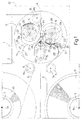
- Number 1 in Figure 1 indicates as a whole a unit for feeding strips to a packing machine (not shown) for producing packets of cigarettes.
- Unit 1 comprises a frame 2, which supports two pins 3 and 4, a splicing device 5, and two guide pulleys 6 and 7 for respective strips 8 and 9.
- Pins 3 and 4 support respective reels 10 and 11, from which respective strips 8 and 9 are unwound; and pins 3, 4 and pulleys 6, 7 rotate about respective axes 3a, 4a, 6a, 7a parallel to one another and perpendicular to the Figure 1 plane.
- Splicing device 5 is equidistant from pins 3 and 4, and defines, together with pulley 6, a portion of the path P1 of strip 8, and, together with pulley 7, a portion of the path P2 of strip 9 (Figure 5).
- Splicing device 5 comprises a plate 12 fixed to frame 2 and fitted with two drums 13 and 14 rotating about respective axes 13a and 14a parallel to axes 3a and 4a; a cutting tool 15; two plates 16 and 17 adjacent to first and second drum 13 and 14 respectively; and a guide pulley 18, which rotates about an axis 18a parallel to axes 13a and 14a, and defines both paths P1 and P2.
- Unit 1 and device 5 are substantially specularly symmetrical with respect to an axis A.
- Each drum 13, 14 has a cylindrical face 19, 20 looped about axis 13a, 14a and defined by a curved face 21, 22 extending about axis 13a, 14a, and by a flat face 23, 24 parallel to axis 13a, 14a.
- the term cylindrical face is used in the sense of a cylinder being any solid defined by generating lines parallel to an axis and distributed along a closed path about the axis.
- curved faces 21 and 22 are defined by generating lines parallel to axes 13a and 14a and distributed along two arcs extending more than 180° about axes 13a and 14a
- flat faces 23 and 24 are defined by generating lines parallel to axes 13a and 14a and distributed along two chords, which subtend two arcs of less than 180° and complementary to the previous arcs. Consequently, the distance (radius) between axes 13a, 14a and curved faces 21, 22 is greater than the distance (chord distance) between flat faces 23, 24 and axes 13a, 14a.
- the circular shape of drums 13 and 14 is interrupted by flat faces 23 and 24, which connect the ends of curved faces 21 and 22.
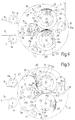
- Drums 13 and 14 also comprise respective suction channels 25 and 26, which come out along faces 21 and 22, close to faces 23 and 24; and drums 13 and 14 rotate in opposite directions about respective axes 13a and 14a to assume a first rest position (Figure 1) and a second rest position (Figure 5), in which they are offset angularly by 180° with respect to a symmetrical position with respect to axis A. That is, both flat faces 23 and 24 are parallel and face upwards in Figure 1, and are parallel and face downwards in Figure 5.
- Plates 16 and 17 have respective concave faces 27 and 28, which face each other, communicate with respective suction channels 29 and 30, and have respective ends adjacent to respective drums 13 and 14.
- Cutting tool 15 is located along axis of symmetry A, between pins 3, 4 and drums 13, 14, and comprises a fixed portion 31 for guiding strips 8 and 9 along a face 32 perpendicular to the Figure 1 plane; and a movable assembly 33 movable about an axis 33a perpendicular to the Figure 1 plane.
- Movable assembly 33 comprises two blades 34 and 35, which are movable between a rest position, not interfering with paths P1 and P2; a first work position, in which blade 34 interferes with path P1 to cut strip 8; and a second work position, in which blade 35 interferes with path P2 to cut strip 9.
- Drums 13, 14 and assembly 33 are rotated about respective axes 13a, 14a, 33a by a single drive member 36 shown schematically in Figure 2.
- Drive member 36 which is preferably an electric step motor, drives a gear 37, which rotates about an axis 37a and meshes with a gear 38 integral with drum 13 and rotating about axis 13a.
- Gear 38 meshes with a gear 39 integral with drum 14 and rotating about axis 14a.
- drum 13 is integral with two cams 40 and 41, which rotate about axis 13a, and cooperate with two tappets 42 and 43 on the free ends of a fork 44 integral with movable assembly 33 to swing blades 34 and 35 about axis 33a as a function of the position of drums 13 and 14.
- strip 8 is fed off reel 10 and along path P1 to the packing machine (not shown), which exerts pull on strip 8 to stretch it between reel 10, pulley 6, face 32 of cutting tool 15, curved face 21 of drum 13, and pulley 18, to define path P1 of strip 8.
- strip 8 drawn by the packing machine (not shown) slides on faces 32 and 21, and rolls about pulleys 6 and 18.
- strip 9 On the other side of axis A, strip 9 has a free end with a sticker 45 with an adhesive face 46, as shown more clearly in Figure 6.
- strip 9 partly rests on concave face 28, and the end of strip 9 rests on face 22 of face 20 of drum 14, at suction channel 26. In this position, adhesive face 46 of sticker 45 faces outwards, as shown clearly in Figure 6.
- respective flat faces 23 and 24 of drums 13 and 14 are positioned parallel and facing upwards, so that flat face 24 of drum 14 faces and is a given distance from curved face 21, along which strip 8 runs. In this first rest position of drums 13 and 14, a gap for the passage of strip 8 is defined between faces 21 and 24.
- device 5 in addition to guiding and supporting strips 8 and 9, commences the splicing process, which, as shown in Figures 4 and 7, comprises synchronously rotating drum 14 clockwise and drum 13 anticlockwise by means of drive member 36 and gears 37, 38, 39 ( Figure 2), so that curved faces 21 and 22 face each other and press together strip 8, strip 9, and sticker 45, the adhesive face 46 of which adheres to strip 8 ( Figure 7).
- Rotation of drum 13 also rotates cams 40 and 41, which swing blades 34 and 35 clockwise in Figure 1, so that blade 34 interferes with path P1 of strip 8 to cut strip 8. Further rotation brings drums 13 and 14 into the second rest position ( Figure 5), in which flat faces 23 and 24 face downwards.
- strip 9 is fed along path P2 to the packing machine (not shown).
- Strip 9, drawn by the packing machine (not shown) runs along curved face 22, which faces flat face 23 of drum 13 to form a gap for the passage of strip 9.
- the run-out reel 10 is changed with a new one, from which a strip 8 is unwound and placed resting on concave face 27.
- the free end of strip 8 has a sticker 45 with an adhesive face 46, and is placed on face 21, at suction channel 25, so that splicing device 5 is ready to splice strips 8 and 9 as reel 11 is about to run out.
- Splicing is effected by further rotating drums 13 and 14 into the first rest position ( Figure 1), in the course of which, cams 40 and 41 swing movable assembly 33 in the opposite direction to before to cut strip 9.
- drum 13 is always rotated anticlockwise, and drum 14 clockwise.
- Which functional characteristic depends substantially on the shape of drums 13 and 14, and provides for simplifying the actuating mechanisms of splicing device 5.
Landscapes
- Replacement Of Web Rolls (AREA)
- Basic Packing Technique (AREA)
Abstract
Description
Claims (22)
- A splicing device for splicing a first strip (8) fed off a first reel (10), and a second strip (9) fed off a second reel (11); the device being characterized by comprising a first drum (13) rotating about a first axis (13a) and having a first face (19) for selectively retaining and guiding the first strip (8); and a second drum (14) rotating about a second axis (14a) and having a second face (20) for selectively guiding and retaining the second strip (9); the first and second face (19, 20) being so shaped as to form a gap between said first and said second face (19, 20), and to selectively press the first (8) and second (9) strip together as a function of given indexing angles of the first and second drum (13, 14).
- A device as claimed in Claim 1, characterized in that the first and second face (19, 20) are looped respectively about the first and second axis (13a, 14a), and comprise, respectively, a first and a second curved face (21, 22), which press the first and second strip (8, 9) together at given indexing angles of the first and second drum (13, 14).
- A device as claimed in Claim 2, characterized in that the first and second face (19, 20) respectively comprise a first and a second connecting face (23, 24); the curved faces (21, 22) being located at a greater distance than the first and second connecting face (23, 24) from the respective first and second axis (13a, 14a).
- A device as claimed in Claim 3, characterized in that the first and second connecting face (23, 24) are flat and parallel to the first and second axis (13a, 14a) respectively.
- A device as claimed in any one of Claims 2 to 4, characterized in that said first and said second drum (13, 14) have respective suction channels (25, 26), which come out along the first and second face (19, 20) respectively to retain the respective free ends of the first and second strip (8, 9).
- A device as claimed in any one of Claims 1 to 5, characterized by comprising a cutting tool (15) located along an axis (A) of symmetry of the splicing device (5); the axis (A) of symmetry extending between said first and said second drum (13, 14).
- A device as claimed in Claim 6, characterized in that the cutting tool (15) comprises a fixed portion (31) and a movable assembly (33).
- A device as claimed in Claim 7, characterized in that the fixed portion (31) comprises an outer face (32), which defines, together with the first drum (13), a portion of a first path (P1) of the first strip (8), and defines, together with the second drum (14), a portion of a second path (P2) of the second strip (9).
- A device as claimed in Claim 8, characterized in that the movable assembly (33) comprises a first and a second blade (34, 35), and swings about a third axis (33a) to selectively position the first blade (34) to interfere with the first strip (8) along the first path (P1), and the second blade (35) to interfere with the second strip (9) along the second path (P2).
- A device as claimed in any one of Claims 7 to 9, characterized in that the first and second drum (13, 14) and the movable assembly (33) are driven by a single drive member (36).
- A device as claimed in Claim 10, characterized in that the first and second drum (13, 14) are connected to each other by respective gears (38, 39).
- A device as claimed in Claim 10 or 11, characterized by comprising at least one cam (40, 41) rotating about one of the axes (13a, 14a) of the first and second drum (13, 14) and integral with the first and second drum (13, 14); said movable assembly (33) being integral with at least one tappet (42, 43) to activate the blades (34, 35) as a function of the position of the first and second drum (13; 14).
- A device as claimed in any one of the foregoing Claims, characterized by comprising a first and a second plate (16, 17) comprising, respectively, a first and a second seating face (27, 28), along which respective suction channels (29, 30) come out to retain the first and second strip (8, 9).
- A device as claimed in Claim 13, characterized in that the first and second seating face (27, 28) have ends adjacent to the first and second drum (13, 14) respectively.
- A device as claimed in Claim 13 or 14, characterized in that the first and second seating face (27, 28) face each other.
- A device as claimed in any one of Claims 13 to 15, characterized in that the first and second seating face (27, 28) are concave.
- A method of splicing a first strip (8) fed off a first reel (10), and a second strip (9) fed off a second reel (11); the second strip (9) having a sticker (45) on its free end; and the method being characterized by guiding the first strip (8) along a first face (19) of a first drum (13), and retaining said free end of the second strip (9) by means of a second face (20) of a second drum (14) and the sticker (45) on the second face (20) of the second drum (14); and rotating the first and the second drum (13, 14) about a first and a second axis (13a, 14a) respectively, to press the first and the second strip (8, 9) and the sticker (45) together and so splice the first and the second strip (8, 9).
- A method as claimed in Claim 17, characterized in that the first and second face (19, 20) respectively comprise a first and a second curved face (21, 22); and a first and a second connecting face (23, 24), the distance of which from the respective first and second axis (13a, 14a) is less than the distance between the first and second curved face (21, 22) and the respective first and second axis (13a, 14a).
- A method as claimed in Claim 18, characterized by indexing said first and said second drum (13, 14) about the first and second axis (13a, 14a) respectively, so as to position the first curved face (21) facing the second connecting face (24) to allow the first strip (8) to run along the first drum (13).
- A method as claimed in Claim 18, characterized by indexing the first and second drum (13, 14), so that the first curved face (21) faces the second curved face (22) to press the first and second strip (8, 9) and said sticker (45) together.
- A method as claimed in Claim 20, characterized by stretching the first strip (8) between a fixed portion (32) of a cutting tool (15) and the first drum (13); moving a blade (34) into a position to interfere with said first strip (8); and cutting said first strip (8) between said fixed portion (32) and the first drum (13).
- A method as claimed in Claim 21, characterized by indexing the first and second drum (13, 14) to position the first connecting face (23) facing the second curved face (22), so as to allow the second strip (9) to run on the second curved face (22).
Applications Claiming Priority (2)
| Application Number | Priority Date | Filing Date | Title |
|---|---|---|---|
| ITBO20020531 | 2002-08-08 | ||
| IT000531A ITBO20020531A1 (en) | 2002-08-08 | 2002-08-08 | TAPE JOINTING DEVICE AND METHOD. |
Publications (2)
| Publication Number | Publication Date |
|---|---|
| EP1388513A2 true EP1388513A2 (en) | 2004-02-11 |
| EP1388513A3 EP1388513A3 (en) | 2004-11-03 |
Family
ID=30130763
Family Applications (1)
| Application Number | Title | Priority Date | Filing Date |
|---|---|---|---|
| EP03102393A Withdrawn EP1388513A3 (en) | 2002-08-08 | 2003-07-31 | Strip splicing device and method |
Country Status (5)
| Country | Link |
|---|---|
| US (1) | US6881289B2 (en) |
| EP (1) | EP1388513A3 (en) |
| JP (1) | JP2004131285A (en) |
| CN (1) | CN100411963C (en) |
| IT (1) | ITBO20020531A1 (en) |
Cited By (1)
| Publication number | Priority date | Publication date | Assignee | Title |
|---|---|---|---|---|
| EP3957583A4 (en) * | 2019-04-17 | 2023-07-05 | Dongguan Areconn Precision Machine Co.,Ltd | AUTOMATIC SWITCHING DEVICE FOR WINDED MATERIAL |
Families Citing this family (44)
| Publication number | Priority date | Publication date | Assignee | Title |
|---|---|---|---|---|
| US7392960B2 (en) * | 2002-10-25 | 2008-07-01 | The Procter & Gamble Company | Method for unwinding rolls of web material |
| US6978816B1 (en) * | 2004-12-17 | 2005-12-27 | The Procter & Gamble Company | Method and apparatus for splicing a web material |
| DE102005033486A1 (en) * | 2005-07-19 | 2007-01-25 | Krones Ag | Device and method for splicing label strips |
| JP4507199B2 (en) * | 2005-09-29 | 2010-07-21 | 富士フイルム株式会社 | Web joining apparatus and method |
| US8002924B2 (en) * | 2009-01-27 | 2011-08-23 | Tamarack Products, Inc. | Apparatus for splicing webs |
| US10632740B2 (en) | 2010-04-23 | 2020-04-28 | Landa Corporation Ltd. | Digital printing process |
| US10569534B2 (en) | 2012-03-05 | 2020-02-25 | Landa Corporation Ltd. | Digital printing system |
| US9498946B2 (en) | 2012-03-05 | 2016-11-22 | Landa Corporation Ltd. | Apparatus and method for control or monitoring of a printing system |
| US9643403B2 (en) | 2012-03-05 | 2017-05-09 | Landa Corporation Ltd. | Printing system |
| DE202013012736U1 (en) | 2012-03-05 | 2018-12-20 | Landa Corporation Ltd. | Ink film constructions |
| US9902147B2 (en) | 2012-03-05 | 2018-02-27 | Landa Corporation Ltd. | Digital printing system |
| US10434761B2 (en) | 2012-03-05 | 2019-10-08 | Landa Corporation Ltd. | Digital printing process |
| EP2822778B1 (en) | 2012-03-05 | 2019-05-08 | Landa Corporation Ltd. | Digital printing process |
| US10642198B2 (en) | 2012-03-05 | 2020-05-05 | Landa Corporation Ltd. | Intermediate transfer members for use with indirect printing systems and protonatable intermediate transfer members for use with indirect printing systems |
| BR112014021786B1 (en) | 2012-03-05 | 2021-06-08 | Landa Corporation Ltd | paint film structures |
| US9517618B2 (en) | 2012-03-15 | 2016-12-13 | Landa Corporation Ltd. | Endless flexible belt for a printing system |
| CN103224156A (en) * | 2013-05-25 | 2013-07-31 | 昆明鼎承科技有限公司 | Strip direct splicing device |
| GB201401173D0 (en) | 2013-09-11 | 2014-03-12 | Landa Corp Ltd | Ink formulations and film constructions thereof |
| CN104444503B (en) * | 2013-09-17 | 2016-09-14 | 云南省玉溪市科技彩印有限公司 | Multistation Rotary thermoprint anodized aluminium synchronizes change of lap and automatic label integral device |
| CN103738760B (en) * | 2013-12-23 | 2016-09-28 | 江阴东恒新材料科技有限公司 | The blowing of a kind of coiled material and coil replacing mechanism |
| CN110562785A (en) * | 2014-01-10 | 2019-12-13 | 深圳市宝尔威精密机械有限公司 | Driving mechanism of material belt connecting machine |
| CN104192641A (en) * | 2014-07-21 | 2014-12-10 | 张晋凯 | Automatic wire replacing and connecting method and device in wire arrangement process |
| CN105501533A (en) * | 2014-09-25 | 2016-04-20 | 中烟机械技术中心有限责任公司 | Device used for splicing roll type raw and auxiliary materials and splicing method |
| CN105084067B (en) * | 2015-03-11 | 2017-02-01 | 杜显龙 | Food packaging device dissipating heat through water cooling and application method of food packaging device |
| GB2536489B (en) | 2015-03-20 | 2018-08-29 | Landa Corporation Ltd | Indirect printing system |
| GB2537813A (en) * | 2015-04-14 | 2016-11-02 | Landa Corp Ltd | Apparatus for threading an intermediate transfer member of a printing system |
| GB201609463D0 (en) | 2016-05-30 | 2016-07-13 | Landa Labs 2012 Ltd | Method of manufacturing a multi-layer article |
| DE112017002714T5 (en) | 2016-05-30 | 2019-02-28 | Landa Corporation Ltd. | Digital printing process |
| US10457512B2 (en) | 2016-09-19 | 2019-10-29 | New Era Converting Machinery, Inc. | Automatic lapless butt material splice |
| CN111212736B (en) | 2017-10-19 | 2021-11-23 | 兰达公司 | Endless flexible belt for a printing system |
| WO2019097464A1 (en) | 2017-11-19 | 2019-05-23 | Landa Corporation Ltd. | Digital printing system |
| US11511536B2 (en) | 2017-11-27 | 2022-11-29 | Landa Corporation Ltd. | Calibration of runout error in a digital printing system |
| US11707943B2 (en) | 2017-12-06 | 2023-07-25 | Landa Corporation Ltd. | Method and apparatus for digital printing |
| US11679615B2 (en) | 2017-12-07 | 2023-06-20 | Landa Corporation Ltd. | Digital printing process and method |
| IL279556B2 (en) | 2018-06-26 | 2024-06-01 | Landa Corp Ltd | An intermediate transfer member for a digital printing system |
| US10994528B1 (en) | 2018-08-02 | 2021-05-04 | Landa Corporation Ltd. | Digital printing system with flexible intermediate transfer member |
| US12001902B2 (en) | 2018-08-13 | 2024-06-04 | Landa Corporation Ltd. | Correcting distortions in digital printing by implanting dummy pixels in a digital image |
| US11318734B2 (en) | 2018-10-08 | 2022-05-03 | Landa Corporation Ltd. | Friction reduction means for printing systems and method |
| CN113272144B (en) | 2018-12-24 | 2023-04-04 | 兰达公司 | Digital printing system and method |
| WO2020202145A1 (en) | 2019-03-31 | 2020-10-08 | Landa Corporation Ltd | Systems and methods for preventing or minimizing printing defects in printing processes |
| WO2021105806A1 (en) | 2019-11-25 | 2021-06-03 | Landa Corporation Ltd. | Drying ink in digital printing using infrared radiation absorbed by particles embedded inside itm |
| US11321028B2 (en) | 2019-12-11 | 2022-05-03 | Landa Corporation Ltd. | Correcting registration errors in digital printing |
| CN114868087A (en) | 2019-12-29 | 2022-08-05 | 兰达公司 | Printing method and system |
| JP2024506561A (en) | 2021-02-02 | 2024-02-14 | ランダ コーポレイション リミテッド | Reduce distortion in printed images |
Family Cites Families (12)
| Publication number | Priority date | Publication date | Assignee | Title |
|---|---|---|---|---|
| DE1141848B (en) * | 1961-04-26 | 1962-12-27 | Niepmann & Co Maschf Fr | Device for connecting the rear end of a running material web to the front end of a new web |
| JPS4838461B1 (en) * | 1969-02-26 | 1973-11-17 | ||
| JPS4912329B1 (en) * | 1970-02-17 | 1974-03-23 | ||
| US3738537A (en) | 1971-12-07 | 1973-06-12 | Sunbeam Plastics Corp | Safety closure for aerosol can |
| JPS5329174B2 (en) * | 1973-11-29 | 1978-08-18 | ||
| US4123314A (en) * | 1977-08-19 | 1978-10-31 | Conwed Corporation | Apparatus and method for joining webs on the fly |
| JPS6050693B2 (en) * | 1977-12-28 | 1985-11-09 | 富士写真フイルム株式会社 | Web butt joining method and device |
| IT1166077B (en) * | 1979-04-03 | 1987-04-29 | Carle E Montanari Spa | JOINING DEVICE PARTICULARLY SUITABLE FOR ENSURING CONTINUITY OF WRAPPING MATERIAL TO PACKAGING MACHINES |
| DE3923163A1 (en) * | 1989-07-13 | 1991-01-17 | Kronseder Maschf Krones | METHOD AND DEVICE FOR FITTING ON PRINTED LABEL TAPES |
| DE3929981C1 (en) * | 1989-09-08 | 1991-03-07 | Maschinenfabrik Alfred Schmermund Gmbh & Co, 5820 Gevelsberg, De | |
| IT1263427B (en) * | 1993-06-01 | 1996-08-05 | Gd Spa | DEVICE FOR THE AUTOMATIC JOINT OF TAPES OF SMALL TRANSVERSAL DIMENSIONS. |
| IT1299879B1 (en) * | 1998-03-05 | 2000-04-04 | Gd Spa | FEEDING UNIT OF A BELT TO A USING MACHINE. |
-
2002
- 2002-08-08 IT IT000531A patent/ITBO20020531A1/en unknown
-
2003
- 2003-07-31 US US10/632,142 patent/US6881289B2/en not_active Expired - Fee Related
- 2003-07-31 EP EP03102393A patent/EP1388513A3/en not_active Withdrawn
- 2003-08-06 JP JP2003287782A patent/JP2004131285A/en active Pending
- 2003-08-08 CN CNB031277055A patent/CN100411963C/en not_active Expired - Fee Related
Cited By (1)
| Publication number | Priority date | Publication date | Assignee | Title |
|---|---|---|---|---|
| EP3957583A4 (en) * | 2019-04-17 | 2023-07-05 | Dongguan Areconn Precision Machine Co.,Ltd | AUTOMATIC SWITCHING DEVICE FOR WINDED MATERIAL |
Also Published As
| Publication number | Publication date |
|---|---|
| US6881289B2 (en) | 2005-04-19 |
| US20040103978A1 (en) | 2004-06-03 |
| CN100411963C (en) | 2008-08-20 |
| ITBO20020531A1 (en) | 2004-02-09 |
| JP2004131285A (en) | 2004-04-30 |
| EP1388513A3 (en) | 2004-11-03 |
| CN1493514A (en) | 2004-05-05 |
Similar Documents
| Publication | Publication Date | Title |
|---|---|---|
| US6881289B2 (en) | Strip splicing device and method | |
| US4723724A (en) | Web winding machine and method | |
| US4962897A (en) | Web winding machine and method | |
| US4856725A (en) | Web winding machine and method | |
| JP3587527B2 (en) | Web rewinding device usable for cores with different diameters | |
| RU2567202C2 (en) | Rewinder and production of reels from roll material | |
| RU2169691C2 (en) | Rewinding and cutting machine tool with roll rear end terminating device | |
| JP4452614B2 (en) | Winding device for forming web material logs and method therefor | |
| AU2005218026B2 (en) | Multiprocessing apparatus for forming logs of web material and log manufacture process | |
| KR100202226B1 (en) | Rewinding machine and method for the formation of logs of web material with means for severing the web material | |
| US3791602A (en) | Roll rewinder transfer apparatus and method | |
| CA1257241A (en) | Process and apparatus for changing reels in connection with packaging machines | |
| ITFI20100245A1 (en) | "REWINDING MACHINE AND WINDING METHOD" | |
| US5297751A (en) | Method of replacing strip material on a manufacturing machine | |
| EP1097894B1 (en) | A unit for generating discrete lengths of paper material from a continuous strip | |
| JP4012030B2 (en) | Tobacco making machine delivery unit | |
| CN112654571A (en) | Device for unwinding a web and machine for embossing elements in sheet form | |
| CN205526948U (en) | Reeling device | |
| KR102219005B1 (en) | Slitter for cutting cord band | |
| CA1322357C (en) | Web winding machine and method | |
| JP2649898B2 (en) | Disposable toilet seat manufacturing equipment | |
| EP1205414A2 (en) | Peripheral rewinding machine and method for producing logs of web material | |
| JP2000335793A (en) | Web splicing device and spliced web formation method | |
| JPH03223054A (en) | Slitter rewinder | |
| JPH0818737B2 (en) | Web winding machine and method |
Legal Events
| Date | Code | Title | Description |
|---|---|---|---|
| PUAI | Public reference made under article 153(3) epc to a published international application that has entered the european phase |
Free format text: ORIGINAL CODE: 0009012 |
|
| AK | Designated contracting states |
Kind code of ref document: A2 Designated state(s): AT BE BG CH CY CZ DE DK EE ES FI FR GB GR HU IE IT LI LU MC NL PT RO SE SI SK TR |
|
| AX | Request for extension of the european patent |
Extension state: AL LT LV MK |
|
| PUAL | Search report despatched |
Free format text: ORIGINAL CODE: 0009013 |
|
| AK | Designated contracting states |
Kind code of ref document: A3 Designated state(s): AT BE BG CH CY CZ DE DK EE ES FI FR GB GR HU IE IT LI LU MC NL PT RO SE SI SK TR |
|
| AX | Request for extension of the european patent |
Extension state: AL LT LV MK |
|
| 17P | Request for examination filed |
Effective date: 20050429 |
|
| AKX | Designation fees paid |
Designated state(s): AT BE BG CH CY CZ DE DK EE ES FI FR GB GR HU IE IT LI LU MC NL PT RO SE SI SK TR |
|
| STAA | Information on the status of an ep patent application or granted ep patent |
Free format text: STATUS: THE APPLICATION IS DEEMED TO BE WITHDRAWN |
|
| 18D | Application deemed to be withdrawn |
Effective date: 20080201 |