EP1388484A1 - Lenkstockmodul und Montageverfahren - Google Patents
Lenkstockmodul und Montageverfahren Download PDFInfo
- Publication number
- EP1388484A1 EP1388484A1 EP03400024A EP03400024A EP1388484A1 EP 1388484 A1 EP1388484 A1 EP 1388484A1 EP 03400024 A EP03400024 A EP 03400024A EP 03400024 A EP03400024 A EP 03400024A EP 1388484 A1 EP1388484 A1 EP 1388484A1
- Authority
- EP
- European Patent Office
- Prior art keywords
- steering column
- rotor
- column module
- section
- coding element
- Prior art date
- Legal status (The legal status is an assumption and is not a legal conclusion. Google has not performed a legal analysis and makes no representation as to the accuracy of the status listed.)
- Granted
Links
- 238000000034 method Methods 0.000 title claims abstract description 6
- 230000036316 preload Effects 0.000 claims abstract description 7
- 210000002105 tongue Anatomy 0.000 claims abstract description 7
- 238000004804 winding Methods 0.000 claims description 46
- 230000033001 locomotion Effects 0.000 claims description 15
- 239000000463 material Substances 0.000 claims description 8
- 239000004033 plastic Substances 0.000 claims description 8
- 239000007769 metal material Substances 0.000 claims description 3
- 230000008878 coupling Effects 0.000 claims 2
- 238000010168 coupling process Methods 0.000 claims 2
- 238000005859 coupling reaction Methods 0.000 claims 2
- 238000001125 extrusion Methods 0.000 claims 1
- 238000003860 storage Methods 0.000 description 7
- 238000004519 manufacturing process Methods 0.000 description 5
- 238000009434 installation Methods 0.000 description 3
- 238000001746 injection moulding Methods 0.000 description 2
- 239000002184 metal Substances 0.000 description 2
- 239000002991 molded plastic Substances 0.000 description 2
- 230000005540 biological transmission Effects 0.000 description 1
- 239000004020 conductor Substances 0.000 description 1
- 238000005520 cutting process Methods 0.000 description 1
- 238000001514 detection method Methods 0.000 description 1
- 238000002347 injection Methods 0.000 description 1
- 239000007924 injection Substances 0.000 description 1
- 238000004080 punching Methods 0.000 description 1
- 238000005070 sampling Methods 0.000 description 1
- 230000006641 stabilisation Effects 0.000 description 1
- 238000011105 stabilization Methods 0.000 description 1
Images



Classifications
-
- B—PERFORMING OPERATIONS; TRANSPORTING
- B62—LAND VEHICLES FOR TRAVELLING OTHERWISE THAN ON RAILS
- B62D—MOTOR VEHICLES; TRAILERS
- B62D15/00—Steering not otherwise provided for
- B62D15/02—Steering position indicators ; Steering position determination; Steering aids
Definitions
- the invention relates to a steering column module for a vehicle, with a basic housing, with one with the rotary motion a steering wheel of the vehicle coupled rotor, the Rotor is rotatably mounted on the basic housing and the Steering column module includes a steering angle sensor, the one with the rotor has a non-rotatably coupled coding element.
- the invention also relates to a method for assembling a such steering column module.
- Steering angle sensors usually include one with the Rotational movement of the steering wheel or the steering column coupled Coding element and one not following the rotary movement, stationary scanning unit, which the respective Angular position of the coding element detected. That the The encoding element following rotational movement is in one Sensor housing stored. Steering angle sensors are used for Determination of the respective steering wheel position, based on which on the steering angle of the steerable wheels of the vehicle is closed.
- the head angle is for a variety of Vehicle systems required, for example for braking, Stabilization, navigation, collision avoidance and / or automatic steering systems.
- winding tapes also as Coil springs or referred to as contact spirals, spirally around the steering axis or steering column of the vehicle arranged.
- One end of such a winding tape is via a rotor on the rotatable steering wheel or on the Steering column and the other end is fixed on arranged for example a housing.
- Such one Wrapping tape is used to switch on the steering wheel, Sensors or other electrical or electronic Components that are non-rotatably connected to the steering wheel by means of electrical lines with other electrical or to connect electronic components that are not the Follow the turning movement of the steering wheel.
- the present invention is therefore based on the object based on providing a steering column module, on the one hand very compact and secondly, safe storage of the rotor guaranteed.
- the rotor largely free of play in the axial direction his.
- the invention is characterized in that the rotor Has spring elements which are mounted on the vehicle Condition of the steering column module are suitable in axial Direction under tension against a vehicle side Plant section to act.
- the provision of such Spring elements has the advantage that a possibly existing axial play is compensated, whereby the Coding element in a predefined and positionally accurate Location is kept within the housing. Due to the Axial play-free arrangement of the coding element is a exact scanning by a sensor element of the Steering angle sensor possible; the steering angle can be therefore determine very precisely.
- the rotor is advantageously supported by the spring elements in the axial direction against a defined bearing section applied to the basic housing.
- the storage section can here, for example, as a ring surrounding the rotor, as one or more ring segments or as support webs for be designed the rotor.
- the spring elements do not necessarily have to on the Steering wheel facing side can be arranged. Rather is alternatively or cumulatively conceivable that the spring elements are provided on the side facing away from the steering wheel and act against a system section provided there.
- the Axial play compensation takes place due to the provision of the Spring elements also during the turning movement of the steering wheel instead of.
- the plant section is also the Rotation of the steering wheel follows. Then there is none Relative movement between the rotor and the steering wheel or Contact section. This prevents any noise between the rotor and the steering wheel or the contact section occur.
- Such a steering column module leads to one very quiet operation.
- the spring elements as spring tongues are formed, which are particularly in plan view (Viewing direction along the longitudinal axis) in the radial direction extend and in side view (viewing direction orthogonal to the longitudinal axis) in particular at an angle of 5 ° to 85 ° are arranged perpendicular to the longitudinal axis.
- the Angle is then advantageously a value of greater than 0 °.
- the rotor is made of plastic is shaped and when the spring elements to the rotor are molded on.
- the rotor with the spring elements can here in a manufacturing process, for example by Injection molding.
- An advantageous steering column module results when a total of three or more, especially equidistant mutually arranged, spring elements are provided. This ensures that the rotor is evenly in is biased in the axial direction. A tilting of the This counteracts rotors.
- An advantageous embodiment of the invention provides that the basic housing has a winding tape section and a Has sensor section for a steering angle sensor, wherein the rotor passes through the winding tape section and on Sensor section is rotatably mounted.
- a special advantage is that for the one hand the rotor and on the other hand that Coding element of the steering angle sensor only one Storage location must be provided.
- the bearings are consequently on one common depository reduced. This will make a very compact steering column module realized. Installation space in Area of the steering column of a vehicle is consequently saved.
- Another advantage is that by eliminating one Bearing point a noise reduction is achieved.
- the bearing point of the rotor of the winding tape and the bearing of the coding element noise. Due to the provision of only one storage location can only emit noise from this storage location.
- Bearing components must be manufactured with a high degree of accuracy. By reducing to just one storage location Components, and thus manufacturing costs, can be saved.
- the function of the Steering column module is simplified and improved. Through the direct connection of the rotor and the coding element Tolerance chains smaller and assembly accuracy greater. As a result, the signal accuracy of the steering angle sensor increased.
- a preferred embodiment of the invention provides that the rotor largely covers the winding tape section reaches through without contact and only on Sensor section is stored.
- the coding element is advantageously on the rotor, in particular a code disc, the steering angle sensor non-rotatably arranged.
- the coding element can indirectly, with the interposition of intermediate parts, or be attached directly to the rotor.
- the winding tape section and the sensor section in the unmounted state as separate parts that can be handled from one another are formed. This has the advantage that the individual parts as separate preassembled units are preassembled and handled can.
- the winding section has the rotor with the Clock spring on.
- the sensor section includes the Steering angle sensor including coding element.
- the sensor section a centrally inward, collar-like Has bearing section and when the rotor flange-like section with a circumferential bearing groove Includes recording of the bearing section.
- the bearing groove and the bearing section can an axially and / or radially almost play-free storage can be achieved.
- the bearing groove and / or the ring collar must not be fully trained; inventively can bearing groove or collar sections for storing the Rotors are enough.
- the Rotor comprises a rotor base and a driver, wherein the bearing groove in the axial direction by the one hand Rotor base part or an intermediate part and by the other the driver or an intermediate part is formed.
- the Driver which advantageously from the rotor base is designed to be detachable, is assembled when the Steering column module connected to the rotor base part in such a way that the bearing groove is created. If intermediate parts between the driver and the sensor section and / or between the Rotor base part and the sensor section may be provided should, these are advantageously as intermediate rings educated.
- a particularly preferred embodiment of the invention is characterized in that the winding tape section, on the side facing away from the sensor section for the winding tape.
- This has the advantage that the sensor section facing side of the Wrapping tape section including the sensor section Steering angle sensor can cover protectively.
- the Wrapping tape section can thus function as a Take over the housing cover for the sensor section. On the the sensor section facing away from the The winding tape section is then the winding tape in one Recording arranged. As a result, the winding tape collides with it the steering angle sensor not.
- the rotor is advantageously designed such that he the receptacle provided on the winding tape section at least largely, and in particular completely, covers. So that the winding tape is protected in the Wrapping tape section housed.
- the Sensor section on the winding tape section facing Side has the steering angle sensor.
- the Wrapping tape section then serves to cover the Steering angle sensor.
- the driver can locking means for locking the Have coding element and / or the intermediate part.
- the locking means on the Arranged on the inside of the driver in particular in axially extending latching hooks which are in on the Intervening recesses provided in the intermediate part and on the intermediate part facing away from the cordier element Snap in the coding element.
- Steering column module results when the rotor, and in particular the rotor base, on Wrapping tape section is pre-assembled. This allows the Wrapping band section including rotor base part handled separately become.
- the pre-assembly can be done in such a way that the Rotor, and in particular the rotor base, with Locking means, especially with locking hooks, on Wrapping tape section can be locked with great play.
- the base part of the rotor advantageously passes through the Wrap section.
- Another, also particularly preferred Embodiment of the invention is characterized in that that the coding element as a code disk in one piece especially a metallic material that is not compatible with Plastic is overmolded, is formed.
- the code disc consequently consists only of metal.
- code disks for example made of plastic-coated metal.
- the code disk first for implementation of the code edited. This can be done, for example, by Punching or cutting happen.
- a next one Work step will then include sections of the code disc Injection molded plastic. It has been shown that after the Injection molding around the code disk, this often warps. at the scanning of the code disk is, however, of great size Meaning that the code disk lies on one level. A code disc that is not exactly flat can lead to incorrect ones Scanning results and thus incorrectly recorded Lead steering angles.
- non-molded plastic metallic code disc has the advantage that the On the one hand, code disks are inexpensive to manufacture is; on the other hand, it can be guaranteed that the Code disc can be formed exactly flat.
- a level Code disk also has the advantage that no grinding of the Code disc can appear on surrounding components. It has it has always been shown that warped Code disks to an undesirable contact with the Components leading to the code disk. On such touch contact leads to a falsified Capture the code to an unwanted Noise.
- the coding element can be plugged onto the rotor.
- the assembly is advantageously carried out in the axial direction.
- the coding element under Bias is maintained. Due to the preload be guaranteed that the coding element in its predetermined position is held. The preload or the resilience also serves Height clearance compensation. This will make the Steering column module or the steering angle sensor improved and Sampling errors reduced.
- the rotor base and / or the Driver resiliently pointing in the direction of the coding element resilient projections on the assembled state act directly or indirectly against the coding element.
- Such an arrangement is easy to realize and ensures that the coding element in its predetermined position is kept exactly.
- the projections the side facing the coding element press tabs have, in particular, a rectangular cross section exhibit.
- the Basic rotor part is joined to the driver in such a way is screwed in particular that the coding element and if necessary, the intermediate part in the axial direction Preload is held. It works advantageously the protrusions of the rotor base directly against that Coding.
- the driver acts with the interposition of an intermediate part against the other side of the Coding element.
- Another advantageous embodiment of the invention is characterized by the fact that the rotor base part has a Has inner collar and that the driver in Extending direction of the inner ring collar Has attachment sections that over Fasteners, especially over Fixing screws, firmly connected to the inner ring collar are. This connects the rotor base part with to the driver in a simple manner.
- the Fastening sections centering in particular Centering pins are provided, which are used for precise positioning Assembly of the rotor base part with the driver side Centering means, in particular centering recesses, interact.
- centering means for mutual precise installation on the driver, the Intermediate piece and / or the coding element may be provided.
- the task mentioned in the introduction is also supported by a Method for assembling an inventive Steering column module solved.
- the process is characterized by this from that the winding tape section and the rotor or that Rotor base part to be preassembled that the sensor section and pre-assembled the coding element and possibly the driver and that the two pre-assembled units become the Steering column module according to the invention are finally assembled. Due to the pre-assembly of the individual units, this can Steering column module when installed in or shortly before installation Final assembly of the vehicle.
- the assembly takes place advantageously along one direction, in particular the Axial direction.
- the steering column module 10 shown in FIG. 1 is for Arrangement in the area of the steering column of a vehicle intended.
- the steering column module 10 has a central one Breakthrough 12 along the axis 14 for receiving a not shown steering column.
- the housing 16 includes one Wrapping tape section 18 and a sensor section 20. Die two housing sections 18 and 20 are in the unmounted Condition as parts that can be handled separately formed, which is clear from Figs. 3 and 4.
- the winding tape section 18 has on that Sensor section 20 facing away in the area around the central opening 12 a receptacle 22 in the form of a Cylinder countersink.
- the receptacle 22 is used for the receptacle one spirally wound around the axis 14, not shown winding tape.
- Such a wrapping tape too referred to as a clock spring or contact spiral, is used for Transmission of electrical signals between one not shown steering wheel rotatably arranged about the axis 14 and not following the rotation of the steering wheel electrical or electronic components that for example, are housed in the housing 16.
- To one end of the winding tape is stationary on the housing 16 or arranged on the winding tape section 18.
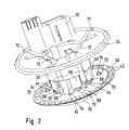
- the other end of the winding tape is on one of the rotational movement of the Steering wheel following rotor 24, which is rotatable on the housing 16 is stored, arranged. 2 is clearly too recognize that a plug section 26 is molded, which for receiving contact means of not shown winding tape is used. At the steering wheel Existing electrical components can Plug section 26 can be contacted with the winding tape.
- the rotor 24 in this case includes a receptacle 22 for the Winding tape completely covering rotor base 28 and a driver 30.
- the driver 30 is with a Driver 30 radially surrounding intermediate ring 32 coupled.
- the sensor section 20 sees in Area around the central breakthrough 12 a centrically after internally directed, annular collar-like bearing section 34.
- the rotor 24, or the driver 30 of the rotor 24 has a flange-like section 36 with a circumferential Bearing groove 38 for receiving the bearing section 34.
- the Bearing groove 38 is in the axial direction by the one hand Driver 36 and on the other hand by the with the driver 36 coupled intermediate ring 32 is formed.
- the rotor 24 a coding element in the form of a code disk 40 rotatably coupled.
- the following the turning movement of the steering wheel Code disc 40 is part of a not shown Steering angle sensor in the sensor section 20 of the housing 16 is housed.
- the code disc 40 has two around Axis 14 concentrically arranged code tracks 42 on the scanned by a scanning unit, not shown become. You can use the code scanned in each case Angle of rotation of the rotor 24 or the steering wheel opposite determine the housing 16 of the steering column module 10.
- the steering column module 10 shown in the figures has the Advantage that there is only one bearing 34, 38 for one the winding tape and the other the code disk 40 having. This can save space, the Manufacturing costs of the steering column module 10 can be reduced Signal accuracy can be improved and a Quality improvement, especially one Noise reduction by reducing the Bearings, can be reached.
- the steering column module 10 also has the advantage that it is on is easy to assemble. This can be done at one of the winding tape section 18 with the rotor 24 or the Rotor base part 28 are preassembled. On the other hand, the Sensor section 20 with the code disk 40 and the driver 30 together with the intermediate ring 32.
- Rotor base part 28 For pre-assembly of the winding tape section 18 with the Rotor base part 28 becomes the rotor base part together with the clock spring axially hidden with the winding tape section 18.
- the Rotor base part 28 sees latching means in the form of Locking hook 44 in front, which can be seen in Fig. 2, wherein this locking hook 44 with a relatively large amount of play on the radial inward lower edge 46 of the receptacle 22 lock. 1, the rear side 47 is one Detection hook 44 to recognize.
- the locking hooks 44 are free Ends extending in the axial direction, in the radial Arranged towards resilient locking webs.
- the code disk 40 and the intermediate ring 32 first the driver 30 in the axial direction from below in the central opening 12 of the sensor section 20 introduced. In a next step, the Intermediate ring 32 with the code disk 40 from above on the Carrier 30 pushed on.
- the driver 30 sees Locking means in the form of locking hooks 48, which for Locking the code disk 40 with the intermediate ring 32 serve.
- the locking hooks 48 are on the inside of the Driver 30 arranged and engage in the intermediate ring 32 and cutouts 50 provided on code disk 40.
- a latching hook 48 is closed in the sectional plane in FIG. 1 detect.
- the back 51 of another latching hook shows also Fig. 1.
- the base part of the rotor is connected in a rotationally fixed manner 28 with the driver 30.
- the rotor base part 28 a centrally inwardly directed inner ring collar 56 before that about fasteners in the form of a total of three Fixing screws 58 with the driver itself in Direction of the inner ring collar 56 extending Fastening sections 60 is connected.
- At least a fastening section 60 is a centering means 62 in Form of a centering pin provided for Positionally accurate assembly of the rotor base 28 with a centering recess 64 provided on the inner ring collar 56 interacts.
- the rotor 24 or the base part of the rotor is advantageously 28 formed as a plastic part. It is advantageous if the spring tongues 72 on the rotor 24 or the rotor base 28 are integrally formed.
Landscapes
- Engineering & Computer Science (AREA)
- Chemical & Material Sciences (AREA)
- Combustion & Propulsion (AREA)
- Transportation (AREA)
- Mechanical Engineering (AREA)
- Power Steering Mechanism (AREA)
- Measurement Of Length, Angles, Or The Like Using Electric Or Magnetic Means (AREA)
- Air Bags (AREA)
- Steering Controls (AREA)
Abstract
Description
- Fig. 1:
- einen Längsschnitt durch ein erfindungsgemäßes Lenkstockmodul in perspektivischer Ansicht;
- Fig. 2:
- den Rotor mit dem Codierelement des Lenkstockmoduls gemäß Fig. 1;
- Fig. 3:
- eine Explosionsdarstellung des Lenkstockmoduls gemäß Fig. 1 in Ansicht von schräg oben; und
- Fig. 4:
- die der Fig. 3 entsprechende Darstellung von schräg unten.
Claims (36)
- Lenkstockmodul (10) für ein Fahrzeug, mit einem Grundgehäuse (16), mit einem mit der Drehbewegung eines Lenkrades des Fahrzeuges koppelbaren Rotor (24), wobei der Rotor (24) am Grundgehäuse (16) drehbar gelagert ist, und wobei das Lenkstockmodul (10) einen Lenkwinkelsensor umfasst, der ein mit dem Rotor (24) drehfest gekoppeltes Codierelement (40) aufweist, dadurch gekennzeichnet, dass der Rotor (24) Federelemente (72) aufweist, die im am Fahrzeug montierten Zustand des Lenkstockmoduls (10) dazu geeignet sind in axialer Richtung unter Vorspannung gegen einen fahrzeugseitigen Anlageabschnitt zu wirken.
- Lenkstockmodul (10) nach Anspruch 1, dadurch gekennzeichnet, dass der Rotor (24) durch die Federelemente (72) in axialer Richtung gegen einen definierten Lagerabschnitt (34) am Grundgehäuse (16) beaufschlagt wird, wobei der Lagerabschnitt (34) insbesondere als ein den Rotor (24) umgebender Ring, als ein oder mehrere Ringsegmente oder als Auflagestege ausgebildet sein kann.
- Lenkstockmodul (10) nach Anspruch 1 oder 2, dadurch gekennzeichnet, dass die Federelemente (72) auf der dem Lenkrad zugewandten Seite des Rotors (24) angeordnet sind.
- Lenkstockmodul (10) nach Anspruch 1, 2 oder 3, dadurch gekennzeichnet, dass der Anlageabschnitt lenkradseitig angeordnet ist.
- Lenkstockmodul (10) nach einem der vorhergehenden Ansprüche, dadurch gekennzeichnet, dass der Anlageabschnitt der Drehbewegung des Lenkrades folgt.
- Lenkstockmodul (10) nach einem der vorhergehenden Ansprüche, dadurch gekennzeichnet, dass die Federelemente (72) als Federzungen ausgebildet sind, die sich insbesondere in Draufsicht in radialer Richtung erstrecken und in Seitenansicht insbesondere unter einem Winkel von 5° bis 85° senkrecht zur Längsachse (14) angeordnet sind.
- Lenkstockmodul (10) nach einem der vorhergehenden Ansprüche, dadurch gekennzeichnet, dass der Rotor (24) aus Kunststoff geformt ist und dass die Federelemente (72) an den Rotor (24) angeformt sind.
- Lenkstockmodul nach einem der vorhergehenden Ansprüche, dadurch gekennzeichnet, dass insgesamt drei oder mehr, insbesondere äquidistant zueinander angeordnete, Federelemente (72) vorgesehen sind.
- Lenkstockmodul (10) nach einem der vorhergehenden Ansprüche, dadurch gekennzeichnet, dass das Grundgehäuse (16) einen Wickelbandabschnitt (18) für ein Wickelband zur Übertragung von elektrischen Signalen zwischen dem Rotor (24) und dem Grundgehäuse (16) und einen Sensorabschnitt (20) für den Lenkwinkelsensor aufweist, wobei der Rotor (24) den Wickelbandabschnitt (18) durchgreift und am Sensorabschnitt (20) drehbar gelagert ist.
- Lenkstockmodul (10) nach Anspruch 9, dadurch gekennzeichnet, dass der Rotor (24) den Wickelbandabschnitt (18) berührungsfrei durchgreift und ausschließlich am Sensorabschnitt (20) gelagert ist.
- Lenkstockmodul (10) nach Anspruch 9 oder 10, dadurch gekennzeichnet, dass am Rotor (24) ein Codierelement (40) des Lenkwinkelsensors drehfest angeordnet ist.
- Lenkstockmodul (10) nach Anspruch 9, 10 oder 11, dadurch gekennzeichnet, dass der Wickelbandabschnitt (18) und der Sensorabschnitt (20) im unmontierten Zustand als separat voneinander handhabbare Teile ausgebildet sind.
- Lenkstockmodul (10) nach einem der Ansprüche 9 bis 12, dadurch gekennzeichnet, dass der Rotor (24) ein Rotorgrundteil (28), insbesondere zur Kopplung mit dem Wickelband, und einen Mitnehmer (30), insbesondere zur Kopplung mit dem Codierelement (40), umfasst.
- Lenkstockmodul (10) nach einem der Ansprüche 9 bis 13, dadurch gekennzeichnet, dass der Sensorabschnitt (20) einen zentrisch nach innen gerichteten, ringbundartigen Lagerabschnitt (34) aufweist und dass der Rotor (24) einen flanschartigen Abschnitt mit einer wenigstens abschnittsweise umlaufenden Lagernut (38) zur Aufnahme des Lagerabschnitts (34) aufweist, wobei die Lagernut (38) in axialer Richtung insbesondere durch einerseits das Rotorgrundteil (28) oder ein Zwischenteil (32) und durch andererseits den Mitnehmer (30) oder ein Zwischenteil gebildet wird.
- Lenkstockmodul (10) nach Anspruch 14, dadurch gekennzeichnet, dass das Zwischenteil (32) bzw. die Zwischenteile als Zwischenring (32) bzw. Zwischenringe ausgebildet ist bzw. sind.
- Lenkstockmodul (10) nach einem der Ansprüche 9 bis 15, dadurch gekennzeichnet, dass der Wickelbandabschnitt (18) auf der dem Sensorabschnitt (20) abgewandten Seite eine Aufnahme (22) für das Wickelband aufweist.
- Lenkstockmodul (10) nach Anspruch 16, dadurch gekennzeichnet, dass der Rotor (24) die am Wickelbandabschnitt (18) vorgesehene Aufnahme (22) wenigstens weitgehend, und insbesondere vollständig, abdeckt.
- Lenkstockmodul (10) nach einem der Ansprüche 9 bis 17 dadurch gekennzeichnet, dass der Sensorabschnitt (20), insbesondere auf der dem Wickelbandabschnitt (18) zugewandten Seite, den Lenkwinkelsensor aufnimmt.
- Lenkstockmodul (10) nach einem der Ansprüche 9 bis 18 dadurch gekennzeichnet, dass der Mitnehmer (30) samt Codierelement (40) und gegebenenfalls Zwischenteil am Sensorabschnitt (20) vormontierbar ist.
- Lenkstockmodul (10) nach Anspruch 19, dadurch gekennzeichnet, dass der Mitnehmer Rastmittel (48) zur Hinterrastung des Codierelements (40) und/oder des Zwischenteils (32) aufweist.
- Lenkstockmodul (10) nach Anspruch 20, dadurch gekennzeichnet, dass die Rastmittel (48) an der Innenseite des Mitnehmers (30) angeordnete, insbesondere sich in axialer Richtung erstreckende Rasthaken sind, die in an dem Zwischenteil (32) vorgesehene Aussparungen (50) eingreifen und an der dem Zwischenteil (32) abgewandten Seite des Codierelements (40) das Codierelement (40) hinterrasten.
- Lenkstockmodul (10) nach einem der Ansprüche 9 bis 21, dadurch gekennzeichnet, dass der Rotor (24), und insbesondere das Rotorgrundteil (28), am Wickelbandabschnitt (18) vormontierbar ist.
- Lenkstockmodul (10) nach Anspruch 22, dadurch gekennzeichnet, dass der Rotor (24), und insbesondere das Rotorgrundteil (28), mit Rastmittel (44), insbesondere mit Rasthaken, am Wickelbandabschnitt (18) mit großem Spiel verrastbar ist.
- Lenkstockmodul (10) nach einem der vorhergehenden Ansprüche, dadurch gekennzeichnet, dass das Codierelement (40) als Codescheibe einstückig aus insbesondere einem metallischen Werkstoff, der nicht mit Kunststoff umspritzt ist, gebildet ist.
- Lenkstockmodul (10) nach Anspruch 24, dadurch gekennzeichnet, dass das Codierelement (40) flach ausgebildet ist.
- Lenkstockmodul (10) nach 24 oder 25, dadurch gekennzeichnet, dass das Codierelement unmittelbar oder mittelbar zumindest in axialer Richtung zwischen dem Rotorgrundteil (28) und dem Mitnehmer (30) geklemmt gehaltert ist.
- Lenkstockmodul (10) nach Anspruch 24, 25 oder 26, dadurch gekennzeichnet, dass das Rotorgrundteil (28) mit dem Mitnehmer (30) derart gefügt ist, insbesondere verschraubt ist, dass das Codierelement (40) und gegebenenfalls das Zwischenteil (32) in axialer Richtung unter Vorspannung geklemmt gehaltert ist.
- Lenkstockmodul (10) nach einem der Ansprüche 24 bis 27, dadurch gekennzeichnet, dass das Rotorgrundteil (28) und/oder der Mitnehmer (30) in Richtung des Codierelements (40) weisende federnd nachgiebige Vorsprünge (66) aufweisen, die im montierten Zustand mittelbar oder unmittelbar gegen das Codierelement (40) wirken.
- Lenkstockmodul (10) nach Anspruch 28, dadurch gekennzeichnet, dass auf der dem Codierelement (40) abgewandten Seite der Vorsprünge (66) Materialaussparungen (68) zur Realisierung einer federnden nachgiebigen Vorspannung angeordnet sind.
- Lenkstockmodul (10) nach Anspruch 28 oder 29, dadurch gekennzeichnet, dass die Vorsprünge (66) durch die freien Enden von sich in axialer Richtung erstreckenden Stegen gebildet sind, wobei sich die jeweilige Materialaussparung (68) insbesondere nahezu über die gesamte Breite des jeweiligen Stegs (66) erstreckt.
- Lenkstockmodul (10) nach Anspruch 28, 29 oder 30, dadurch gekennzeichnet, dass die Vorsprünge (66) auf der dem Codierelement (40) zugewandten Seite Drucknasen (70) aufweisen.
- Lenkstockmodul (10) nach einem der vorhergehenden Ansprüche, dadurch gekennzeichnet, dass das Rotorgrundteil (28) mit dem Mitnehmer (30) derart gefügt ist, insbesondere verschraubt ist, dass das Codierelement (40) und gegebenenfalls das Zwischenteil (32) in axialer Richtung unter Vorspannung gehaltert ist.
- Lenkstockmodul (10) nach einem der vorhergehenden Ansprüche, dadurch gekennzeichnet, dass das Rotorgrundteil (28) einen Innenringbund (56) aufweist und dass der Mitnehmer (30) sich in Richtung des Innenringbundes (56) erstreckende Befestigungsabschnitte (60) aufweist, die über Befestigungsmittel, insbesondere Befestigungsschrauben (58), mit dem Innenringbund (56) fest verbunden sind.
- Lenkstockmodul (10) nach Anspruch 33, dadurch gekennzeichnet, dass an den Befestigungsabschnitten (60) Zentriermittel (62), insbesondere Zentrierzapfen (62), vorgesehen sind, die zur positionsgenauen Montage des Rotorgrundteils (28) mit mitnehmerseitigen Zentriermitteln, insbesondere Zentrieraussparungen (64), zusammenwirken.
- Lenkstockmodul (10) nach einem der vorhergehenden Ansprüche, dadurch gekennzeichnet, dass der Rotor (24), das Rotorgrundteil (28), der Mitnehmer (30), das Zwischenstück (32) und/oder das Codierelement (40) Zentriermittel (62. 64) zur gegenseitigen positionsgenauen Montage aufweisen.
- Verfahren zur Montage eines Lenkstockmoduls (10) nach einem der vorhergehenden Ansprüche, dadurch gekennzeichnet, dass der Wickelbandabschnitt (18) und der Rotor (24) bzw. das Rotorgrundteil (28) vormontiert werden, dass der Sensorabschnitt (20) und das Codierelement (40) und ggf. der Mitnehmer (30) vormontiert werden und dass die beiden vormontierten Einheiten zu dem Lenkstockmodul (10) endmontiert werden.
Applications Claiming Priority (2)
| Application Number | Priority Date | Filing Date | Title |
|---|---|---|---|
| DE10236142A DE10236142A1 (de) | 2002-08-07 | 2002-08-07 | Lenkstockmodul und Montageverfahren |
| DE10236142 | 2002-08-07 |
Publications (2)
| Publication Number | Publication Date |
|---|---|
| EP1388484A1 true EP1388484A1 (de) | 2004-02-11 |
| EP1388484B1 EP1388484B1 (de) | 2007-12-12 |
Family
ID=30128759
Family Applications (1)
| Application Number | Title | Priority Date | Filing Date |
|---|---|---|---|
| EP03400024A Expired - Lifetime EP1388484B1 (de) | 2002-08-07 | 2003-05-16 | Lenkstockmodul |
Country Status (3)
| Country | Link |
|---|---|
| EP (1) | EP1388484B1 (de) |
| AT (1) | ATE380738T1 (de) |
| DE (2) | DE10236142A1 (de) |
Cited By (3)
| Publication number | Priority date | Publication date | Assignee | Title |
|---|---|---|---|---|
| EP1640248A3 (de) * | 2004-09-28 | 2006-06-07 | TRW Automotive GmbH | Verfahren zur Montage eines Lenkwinkel- und Lenkmomentsensors sowie Lenkgetriebe mit einem Lenkwinkel- und Lenkmomentsensor |
| DE102007055392A1 (de) | 2007-11-20 | 2009-05-28 | Valeo Schalter Und Sensoren Gmbh | Verdrehsicherung eines Rotors und eines Gehäuses eines Wickelbandes sowie ein Wickelband |
| DE102012105966A1 (de) * | 2012-07-04 | 2014-05-08 | Hella Kgaa Hueck & Co. | Drehwinkelsensor |
Citations (3)
| Publication number | Priority date | Publication date | Assignee | Title |
|---|---|---|---|---|
| DE4009007A1 (de) * | 1989-03-22 | 1990-09-27 | Fuji Heavy Ind Ltd | Verfahren zum erfassen des absoluten lenkwinkels eines lenkwinkelsensors fuer ein fahrzeug |
| EP0860330A2 (de) * | 1997-02-24 | 1998-08-26 | Yazaki Corporation | Vorrichtung zur Signalübertragung für eine Lenksäule |
| EP0913319A2 (de) * | 1997-10-29 | 1999-05-06 | Alps Electric Co., Ltd. | Lenkwinkelsensoreinheit |
Family Cites Families (4)
| Publication number | Priority date | Publication date | Assignee | Title |
|---|---|---|---|---|
| JP3273540B2 (ja) * | 1996-02-07 | 2002-04-08 | アルプス電気株式会社 | 回転コネクタの取付構造 |
| DE19649906C2 (de) * | 1996-12-02 | 1999-05-12 | Kostal Leopold Gmbh & Co Kg | Sensor zur Erfassung von Drehwinkeln |
| DE19933049A1 (de) * | 1999-07-15 | 2001-01-18 | Valeo Schalter & Sensoren Gmbh | Lenkstockmodul mit Lenkwinkelsensor und geringer Empfindlichkeit des Lenkwinkelsensors gegenüber Rundlauffehlern der Lenksäule |
| DE10019795B4 (de) * | 2000-04-20 | 2004-09-30 | Delphi Technologies, Inc. (n.d.Ges.d. Staates Delaware), Troy | Lenkstockschalter |
-
2002
- 2002-08-07 DE DE10236142A patent/DE10236142A1/de not_active Withdrawn
-
2003
- 2003-05-16 EP EP03400024A patent/EP1388484B1/de not_active Expired - Lifetime
- 2003-05-16 DE DE50308766T patent/DE50308766D1/de not_active Expired - Lifetime
- 2003-05-16 AT AT03400024T patent/ATE380738T1/de not_active IP Right Cessation
Patent Citations (3)
| Publication number | Priority date | Publication date | Assignee | Title |
|---|---|---|---|---|
| DE4009007A1 (de) * | 1989-03-22 | 1990-09-27 | Fuji Heavy Ind Ltd | Verfahren zum erfassen des absoluten lenkwinkels eines lenkwinkelsensors fuer ein fahrzeug |
| EP0860330A2 (de) * | 1997-02-24 | 1998-08-26 | Yazaki Corporation | Vorrichtung zur Signalübertragung für eine Lenksäule |
| EP0913319A2 (de) * | 1997-10-29 | 1999-05-06 | Alps Electric Co., Ltd. | Lenkwinkelsensoreinheit |
Cited By (4)
| Publication number | Priority date | Publication date | Assignee | Title |
|---|---|---|---|---|
| EP1640248A3 (de) * | 2004-09-28 | 2006-06-07 | TRW Automotive GmbH | Verfahren zur Montage eines Lenkwinkel- und Lenkmomentsensors sowie Lenkgetriebe mit einem Lenkwinkel- und Lenkmomentsensor |
| US7350617B2 (en) | 2004-09-28 | 2008-04-01 | Trw Automotive Gmbh | Method for mounting a steering angle and steering torque sensor and steering gear including a steering angle and steering torque sensor |
| DE102007055392A1 (de) | 2007-11-20 | 2009-05-28 | Valeo Schalter Und Sensoren Gmbh | Verdrehsicherung eines Rotors und eines Gehäuses eines Wickelbandes sowie ein Wickelband |
| DE102012105966A1 (de) * | 2012-07-04 | 2014-05-08 | Hella Kgaa Hueck & Co. | Drehwinkelsensor |
Also Published As
| Publication number | Publication date |
|---|---|
| ATE380738T1 (de) | 2007-12-15 |
| EP1388484B1 (de) | 2007-12-12 |
| DE10236142A1 (de) | 2004-02-19 |
| DE50308766D1 (de) | 2008-01-24 |
Similar Documents
| Publication | Publication Date | Title |
|---|---|---|
| DE69618090T2 (de) | Anlasser-Schütz mit eingebauter elektronische Schaltung, und Kraftfahrzeuganlasser mit solchem Schütz versehen | |
| EP1183167B1 (de) | Vorrichtung zum übertragen von energie | |
| EP2870053B1 (de) | Drehwinkelsensor | |
| EP3448741A1 (de) | Kraftfahrzeuglenkungsbaugruppe | |
| DE102017222999A1 (de) | Sensoreinrichtung für ein Lenksystem eines Fahrzeugs | |
| EP1528656B1 (de) | Bürstenträger für einen elektromotorischen Stellantrieb und elektromotorischer Stellantrieb | |
| WO2018108470A1 (de) | Sensorvorrichtung sowie verfahren zum zusammenbau einer sensorvorrichtung | |
| DE102014108996B4 (de) | Elektrisch betätigte Lenkradschlosseinrichtung | |
| DE602006000388T2 (de) | Verbindungsanordnung eines Drehverbinders mit Steuerwinkelsensor | |
| WO2018219454A1 (de) | Sensoreinheit für ein drehwinkelmesssystem sowie ein drehwinkelmesssystem mit einer derartigen sensoreinheit | |
| DE3411455C2 (de) | ||
| EP1391351B1 (de) | Lenkstockmodul und Montageverfahren | |
| EP1320176B1 (de) | Betätigungsvorrichtung, insbesondere zur Betätigung von Sperrdifferentialen von Fahrzeugen | |
| EP1391350B1 (de) | Lenkstockmodul und Montageverfahren | |
| EP1388484B1 (de) | Lenkstockmodul | |
| DE3411456A1 (de) | Elektrischer drehwinkelgeber | |
| DE102022103482A1 (de) | Drehantriebsvorrichtung | |
| WO2023285333A1 (de) | Drehmomentsensorvorrichtung und verfahren zum zusammenbau einer drehmomentsensorvorrichtung | |
| EP3408144A1 (de) | Lenksäule mit elektrischer lenkungsverriegelung | |
| DE10065240C2 (de) | Lenkwinkelmesseinrichtung | |
| DE69504388T2 (de) | Kraftfahrzeuglenksäulen-Schaltergehäuse | |
| DE102017103643B4 (de) | Stellvorrichtung | |
| EP3325784B1 (de) | Baugruppe für eine stelleinrichtung, insbesondere eines abgasturboladers | |
| EP0829407A2 (de) | Kolben/Zylinder-Anordnung | |
| DE102020115138A1 (de) | Baugruppe für ein Fahrzeug und Fahrzeug |
Legal Events
| Date | Code | Title | Description |
|---|---|---|---|
| PUAI | Public reference made under article 153(3) epc to a published international application that has entered the european phase |
Free format text: ORIGINAL CODE: 0009012 |
|
| AK | Designated contracting states |
Kind code of ref document: A1 Designated state(s): AT BE BG CH CY CZ DE DK EE ES FI FR GB GR HU IE IT LI LU MC NL PT RO SE SI SK TR |
|
| AX | Request for extension of the european patent |
Extension state: AL LT LV MK |
|
| 17P | Request for examination filed |
Effective date: 20040515 |
|
| AKX | Designation fees paid |
Designated state(s): AT BE BG CH CY CZ DE DK EE ES FI FR GB GR HU IE IT LI LU MC NL PT RO SE SI SK TR |
|
| RIN1 | Information on inventor provided before grant (corrected) |
Inventor name: BOSCH, JUERGEN Inventor name: GRUENER, ROLAND |
|
| 17Q | First examination report despatched |
Effective date: 20060831 |
|
| GRAP | Despatch of communication of intention to grant a patent |
Free format text: ORIGINAL CODE: EPIDOSNIGR1 |
|
| GRAS | Grant fee paid |
Free format text: ORIGINAL CODE: EPIDOSNIGR3 |
|
| GRAA | (expected) grant |
Free format text: ORIGINAL CODE: 0009210 |
|
| RTI1 | Title (correction) |
Free format text: STEERING COLUMN MODULE |
|
| AK | Designated contracting states |
Kind code of ref document: B1 Designated state(s): AT BE BG CH CY CZ DE DK EE ES FI FR GB GR HU IE IT LI LU MC NL PT RO SE SI SK TR |
|
| REG | Reference to a national code |
Ref country code: GB Ref legal event code: FG4D Free format text: NOT ENGLISH |
|
| REG | Reference to a national code |
Ref country code: CH Ref legal event code: EP |
|
| REG | Reference to a national code |
Ref country code: IE Ref legal event code: FG4D Free format text: LANGUAGE OF EP DOCUMENT: GERMAN |
|
| REF | Corresponds to: |
Ref document number: 50308766 Country of ref document: DE Date of ref document: 20080124 Kind code of ref document: P |
|
| PG25 | Lapsed in a contracting state [announced via postgrant information from national office to epo] |
Ref country code: SE Free format text: LAPSE BECAUSE OF FAILURE TO SUBMIT A TRANSLATION OF THE DESCRIPTION OR TO PAY THE FEE WITHIN THE PRESCRIBED TIME-LIMIT Effective date: 20080312 |
|
| PG25 | Lapsed in a contracting state [announced via postgrant information from national office to epo] |
Ref country code: NL Free format text: LAPSE BECAUSE OF FAILURE TO SUBMIT A TRANSLATION OF THE DESCRIPTION OR TO PAY THE FEE WITHIN THE PRESCRIBED TIME-LIMIT Effective date: 20071212 Ref country code: FI Free format text: LAPSE BECAUSE OF FAILURE TO SUBMIT A TRANSLATION OF THE DESCRIPTION OR TO PAY THE FEE WITHIN THE PRESCRIBED TIME-LIMIT Effective date: 20071212 Ref country code: SI Free format text: LAPSE BECAUSE OF FAILURE TO SUBMIT A TRANSLATION OF THE DESCRIPTION OR TO PAY THE FEE WITHIN THE PRESCRIBED TIME-LIMIT Effective date: 20071212 |
|
| NLV1 | Nl: lapsed or annulled due to failure to fulfill the requirements of art. 29p and 29m of the patents act | ||
| GBV | Gb: ep patent (uk) treated as always having been void in accordance with gb section 77(7)/1977 [no translation filed] | ||
| PG25 | Lapsed in a contracting state [announced via postgrant information from national office to epo] |
Ref country code: CZ Free format text: LAPSE BECAUSE OF FAILURE TO SUBMIT A TRANSLATION OF THE DESCRIPTION OR TO PAY THE FEE WITHIN THE PRESCRIBED TIME-LIMIT Effective date: 20071212 Ref country code: ES Free format text: LAPSE BECAUSE OF FAILURE TO SUBMIT A TRANSLATION OF THE DESCRIPTION OR TO PAY THE FEE WITHIN THE PRESCRIBED TIME-LIMIT Effective date: 20080323 |
|
| ET | Fr: translation filed | ||
| PG25 | Lapsed in a contracting state [announced via postgrant information from national office to epo] |
Ref country code: RO Free format text: LAPSE BECAUSE OF FAILURE TO SUBMIT A TRANSLATION OF THE DESCRIPTION OR TO PAY THE FEE WITHIN THE PRESCRIBED TIME-LIMIT Effective date: 20071212 Ref country code: SK Free format text: LAPSE BECAUSE OF FAILURE TO SUBMIT A TRANSLATION OF THE DESCRIPTION OR TO PAY THE FEE WITHIN THE PRESCRIBED TIME-LIMIT Effective date: 20071212 |
|
| PG25 | Lapsed in a contracting state [announced via postgrant information from national office to epo] |
Ref country code: PT Free format text: LAPSE BECAUSE OF FAILURE TO SUBMIT A TRANSLATION OF THE DESCRIPTION OR TO PAY THE FEE WITHIN THE PRESCRIBED TIME-LIMIT Effective date: 20080512 |
|
| REG | Reference to a national code |
Ref country code: IE Ref legal event code: FD4D |
|
| PLBE | No opposition filed within time limit |
Free format text: ORIGINAL CODE: 0009261 |
|
| STAA | Information on the status of an ep patent application or granted ep patent |
Free format text: STATUS: NO OPPOSITION FILED WITHIN TIME LIMIT |
|
| PG25 | Lapsed in a contracting state [announced via postgrant information from national office to epo] |
Ref country code: IE Free format text: LAPSE BECAUSE OF FAILURE TO SUBMIT A TRANSLATION OF THE DESCRIPTION OR TO PAY THE FEE WITHIN THE PRESCRIBED TIME-LIMIT Effective date: 20071212 Ref country code: DK Free format text: LAPSE BECAUSE OF FAILURE TO SUBMIT A TRANSLATION OF THE DESCRIPTION OR TO PAY THE FEE WITHIN THE PRESCRIBED TIME-LIMIT Effective date: 20071212 |
|
| 26N | No opposition filed |
Effective date: 20080915 |
|
| PG25 | Lapsed in a contracting state [announced via postgrant information from national office to epo] |
Ref country code: GB Free format text: LAPSE BECAUSE OF FAILURE TO SUBMIT A TRANSLATION OF THE DESCRIPTION OR TO PAY THE FEE WITHIN THE PRESCRIBED TIME-LIMIT Effective date: 20071212 |
|
| BERE | Be: lapsed |
Owner name: VALEO SCHALTER UND SENSOREN G.M.B.H. Effective date: 20080531 |
|
| PG25 | Lapsed in a contracting state [announced via postgrant information from national office to epo] |
Ref country code: MC Free format text: LAPSE BECAUSE OF NON-PAYMENT OF DUE FEES Effective date: 20080531 |
|
| REG | Reference to a national code |
Ref country code: CH Ref legal event code: PL |
|
| PG25 | Lapsed in a contracting state [announced via postgrant information from national office to epo] |
Ref country code: EE Free format text: LAPSE BECAUSE OF FAILURE TO SUBMIT A TRANSLATION OF THE DESCRIPTION OR TO PAY THE FEE WITHIN THE PRESCRIBED TIME-LIMIT Effective date: 20071212 Ref country code: GR Free format text: LAPSE BECAUSE OF FAILURE TO SUBMIT A TRANSLATION OF THE DESCRIPTION OR TO PAY THE FEE WITHIN THE PRESCRIBED TIME-LIMIT Effective date: 20080313 Ref country code: LI Free format text: LAPSE BECAUSE OF NON-PAYMENT OF DUE FEES Effective date: 20080531 Ref country code: CH Free format text: LAPSE BECAUSE OF NON-PAYMENT OF DUE FEES Effective date: 20080531 |
|
| PG25 | Lapsed in a contracting state [announced via postgrant information from national office to epo] |
Ref country code: BE Free format text: LAPSE BECAUSE OF NON-PAYMENT OF DUE FEES Effective date: 20080531 |
|
| PG25 | Lapsed in a contracting state [announced via postgrant information from national office to epo] |
Ref country code: BG Free format text: LAPSE BECAUSE OF FAILURE TO SUBMIT A TRANSLATION OF THE DESCRIPTION OR TO PAY THE FEE WITHIN THE PRESCRIBED TIME-LIMIT Effective date: 20080312 |
|
| PG25 | Lapsed in a contracting state [announced via postgrant information from national office to epo] |
Ref country code: CY Free format text: LAPSE BECAUSE OF FAILURE TO SUBMIT A TRANSLATION OF THE DESCRIPTION OR TO PAY THE FEE WITHIN THE PRESCRIBED TIME-LIMIT Effective date: 20071212 |
|
| PG25 | Lapsed in a contracting state [announced via postgrant information from national office to epo] |
Ref country code: AT Free format text: LAPSE BECAUSE OF NON-PAYMENT OF DUE FEES Effective date: 20080516 |
|
| PG25 | Lapsed in a contracting state [announced via postgrant information from national office to epo] |
Ref country code: HU Free format text: LAPSE BECAUSE OF FAILURE TO SUBMIT A TRANSLATION OF THE DESCRIPTION OR TO PAY THE FEE WITHIN THE PRESCRIBED TIME-LIMIT Effective date: 20080613 Ref country code: LU Free format text: LAPSE BECAUSE OF NON-PAYMENT OF DUE FEES Effective date: 20080516 |
|
| PG25 | Lapsed in a contracting state [announced via postgrant information from national office to epo] |
Ref country code: TR Free format text: LAPSE BECAUSE OF FAILURE TO SUBMIT A TRANSLATION OF THE DESCRIPTION OR TO PAY THE FEE WITHIN THE PRESCRIBED TIME-LIMIT Effective date: 20071212 |
|
| PGFP | Annual fee paid to national office [announced via postgrant information from national office to epo] |
Ref country code: DE Payment date: 20120514 Year of fee payment: 10 |
|
| PGFP | Annual fee paid to national office [announced via postgrant information from national office to epo] |
Ref country code: FR Payment date: 20120615 Year of fee payment: 10 |
|
| PGFP | Annual fee paid to national office [announced via postgrant information from national office to epo] |
Ref country code: IT Payment date: 20120522 Year of fee payment: 10 |
|
| PG25 | Lapsed in a contracting state [announced via postgrant information from national office to epo] |
Ref country code: DE Free format text: LAPSE BECAUSE OF NON-PAYMENT OF DUE FEES Effective date: 20131203 |
|
| REG | Reference to a national code |
Ref country code: DE Ref legal event code: R119 Ref document number: 50308766 Country of ref document: DE Effective date: 20131203 |
|
| PG25 | Lapsed in a contracting state [announced via postgrant information from national office to epo] |
Ref country code: IT Free format text: LAPSE BECAUSE OF NON-PAYMENT OF DUE FEES Effective date: 20130516 |
|
| REG | Reference to a national code |
Ref country code: FR Ref legal event code: ST Effective date: 20140131 |
|
| PG25 | Lapsed in a contracting state [announced via postgrant information from national office to epo] |
Ref country code: FR Free format text: LAPSE BECAUSE OF NON-PAYMENT OF DUE FEES Effective date: 20130531 |