EP1388406A1 - Verfahren und Vorrichtung zur Herstellung blasgeformter Hohlkörper aus thermoplastischen Kunststoffen - Google Patents
Verfahren und Vorrichtung zur Herstellung blasgeformter Hohlkörper aus thermoplastischen Kunststoffen Download PDFInfo
- Publication number
- EP1388406A1 EP1388406A1 EP03017813A EP03017813A EP1388406A1 EP 1388406 A1 EP1388406 A1 EP 1388406A1 EP 03017813 A EP03017813 A EP 03017813A EP 03017813 A EP03017813 A EP 03017813A EP 1388406 A1 EP1388406 A1 EP 1388406A1
- Authority
- EP
- European Patent Office
- Prior art keywords
- extrusion
- nozzle
- mandrel
- nozzle body
- wall thickness
- Prior art date
- Legal status (The legal status is an assumption and is not a legal conclusion. Google has not performed a legal analysis and makes no representation as to the accuracy of the status listed.)
- Granted
Links
- 238000000034 method Methods 0.000 title claims description 19
- 229920001169 thermoplastic Polymers 0.000 title abstract description 5
- 239000004416 thermosoftening plastic Substances 0.000 title abstract description 4
- 238000001125 extrusion Methods 0.000 claims abstract description 77
- 239000000463 material Substances 0.000 claims abstract description 14
- 238000009826 distribution Methods 0.000 claims abstract description 5
- 239000012815 thermoplastic material Substances 0.000 claims description 7
- 239000000155 melt Substances 0.000 claims description 6
- 238000011144 upstream manufacturing Methods 0.000 claims description 4
- 238000004519 manufacturing process Methods 0.000 description 6
- 238000005452 bending Methods 0.000 description 4
- 238000010101 extrusion blow moulding Methods 0.000 description 3
- 239000004033 plastic Substances 0.000 description 3
- 229920003023 plastic Polymers 0.000 description 3
- 238000002360 preparation method Methods 0.000 description 2
- 238000003860 storage Methods 0.000 description 2
- 230000008961 swelling Effects 0.000 description 2
- 238000004378 air conditioning Methods 0.000 description 1
- 230000009286 beneficial effect Effects 0.000 description 1
- 238000000071 blow moulding Methods 0.000 description 1
- 238000007664 blowing Methods 0.000 description 1
- 239000002826 coolant Substances 0.000 description 1
- 230000007812 deficiency Effects 0.000 description 1
- 230000001419 dependent effect Effects 0.000 description 1
- 230000000694 effects Effects 0.000 description 1
- 238000009434 installation Methods 0.000 description 1
- 239000002184 metal Substances 0.000 description 1
- 238000002156 mixing Methods 0.000 description 1
- 230000002787 reinforcement Effects 0.000 description 1
- 238000007789 sealing Methods 0.000 description 1
- 239000002699 waste material Substances 0.000 description 1
Images


Classifications
-
- B—PERFORMING OPERATIONS; TRANSPORTING
- B29—WORKING OF PLASTICS; WORKING OF SUBSTANCES IN A PLASTIC STATE IN GENERAL
- B29C—SHAPING OR JOINING OF PLASTICS; SHAPING OF MATERIAL IN A PLASTIC STATE, NOT OTHERWISE PROVIDED FOR; AFTER-TREATMENT OF THE SHAPED PRODUCTS, e.g. REPAIRING
- B29C48/00—Extrusion moulding, i.e. expressing the moulding material through a die or nozzle which imparts the desired form; Apparatus therefor
- B29C48/25—Component parts, details or accessories; Auxiliary operations
- B29C48/30—Extrusion nozzles or dies
- B29C48/32—Extrusion nozzles or dies with annular openings, e.g. for forming tubular articles
- B29C48/325—Extrusion nozzles or dies with annular openings, e.g. for forming tubular articles being adjustable, i.e. having adjustable exit sections
-
- B—PERFORMING OPERATIONS; TRANSPORTING
- B29—WORKING OF PLASTICS; WORKING OF SUBSTANCES IN A PLASTIC STATE IN GENERAL
- B29C—SHAPING OR JOINING OF PLASTICS; SHAPING OF MATERIAL IN A PLASTIC STATE, NOT OTHERWISE PROVIDED FOR; AFTER-TREATMENT OF THE SHAPED PRODUCTS, e.g. REPAIRING
- B29C48/00—Extrusion moulding, i.e. expressing the moulding material through a die or nozzle which imparts the desired form; Apparatus therefor
- B29C48/03—Extrusion moulding, i.e. expressing the moulding material through a die or nozzle which imparts the desired form; Apparatus therefor characterised by the shape of the extruded material at extrusion
- B29C48/09—Articles with cross-sections having partially or fully enclosed cavities, e.g. pipes or channels
-
- B—PERFORMING OPERATIONS; TRANSPORTING
- B29—WORKING OF PLASTICS; WORKING OF SUBSTANCES IN A PLASTIC STATE IN GENERAL
- B29C—SHAPING OR JOINING OF PLASTICS; SHAPING OF MATERIAL IN A PLASTIC STATE, NOT OTHERWISE PROVIDED FOR; AFTER-TREATMENT OF THE SHAPED PRODUCTS, e.g. REPAIRING
- B29C48/00—Extrusion moulding, i.e. expressing the moulding material through a die or nozzle which imparts the desired form; Apparatus therefor
- B29C48/25—Component parts, details or accessories; Auxiliary operations
- B29C48/30—Extrusion nozzles or dies
- B29C48/32—Extrusion nozzles or dies with annular openings, e.g. for forming tubular articles
- B29C48/325—Extrusion nozzles or dies with annular openings, e.g. for forming tubular articles being adjustable, i.e. having adjustable exit sections
- B29C48/327—Extrusion nozzles or dies with annular openings, e.g. for forming tubular articles being adjustable, i.e. having adjustable exit sections with centering means
-
- B—PERFORMING OPERATIONS; TRANSPORTING
- B29—WORKING OF PLASTICS; WORKING OF SUBSTANCES IN A PLASTIC STATE IN GENERAL
- B29C—SHAPING OR JOINING OF PLASTICS; SHAPING OF MATERIAL IN A PLASTIC STATE, NOT OTHERWISE PROVIDED FOR; AFTER-TREATMENT OF THE SHAPED PRODUCTS, e.g. REPAIRING
- B29C48/00—Extrusion moulding, i.e. expressing the moulding material through a die or nozzle which imparts the desired form; Apparatus therefor
- B29C48/25—Component parts, details or accessories; Auxiliary operations
- B29C48/92—Measuring, controlling or regulating
-
- B—PERFORMING OPERATIONS; TRANSPORTING
- B29—WORKING OF PLASTICS; WORKING OF SUBSTANCES IN A PLASTIC STATE IN GENERAL
- B29C—SHAPING OR JOINING OF PLASTICS; SHAPING OF MATERIAL IN A PLASTIC STATE, NOT OTHERWISE PROVIDED FOR; AFTER-TREATMENT OF THE SHAPED PRODUCTS, e.g. REPAIRING
- B29C49/00—Blow-moulding, i.e. blowing a preform or parison to a desired shape within a mould; Apparatus therefor
- B29C49/02—Combined blow-moulding and manufacture of the preform or the parison
- B29C49/04—Extrusion blow-moulding
- B29C49/0411—Means for defining the wall or layer thickness
- B29C49/04112—Means for defining the wall or layer thickness for varying the thickness
-
- B—PERFORMING OPERATIONS; TRANSPORTING
- B29—WORKING OF PLASTICS; WORKING OF SUBSTANCES IN A PLASTIC STATE IN GENERAL
- B29C—SHAPING OR JOINING OF PLASTICS; SHAPING OF MATERIAL IN A PLASTIC STATE, NOT OTHERWISE PROVIDED FOR; AFTER-TREATMENT OF THE SHAPED PRODUCTS, e.g. REPAIRING
- B29C49/00—Blow-moulding, i.e. blowing a preform or parison to a desired shape within a mould; Apparatus therefor
- B29C49/02—Combined blow-moulding and manufacture of the preform or the parison
- B29C49/04—Extrusion blow-moulding
- B29C49/04116—Extrusion blow-moulding characterised by the die
-
- B—PERFORMING OPERATIONS; TRANSPORTING
- B29—WORKING OF PLASTICS; WORKING OF SUBSTANCES IN A PLASTIC STATE IN GENERAL
- B29C—SHAPING OR JOINING OF PLASTICS; SHAPING OF MATERIAL IN A PLASTIC STATE, NOT OTHERWISE PROVIDED FOR; AFTER-TREATMENT OF THE SHAPED PRODUCTS, e.g. REPAIRING
- B29C49/00—Blow-moulding, i.e. blowing a preform or parison to a desired shape within a mould; Apparatus therefor
- B29C49/22—Blow-moulding, i.e. blowing a preform or parison to a desired shape within a mould; Apparatus therefor using multilayered preforms or parisons
-
- B—PERFORMING OPERATIONS; TRANSPORTING
- B29—WORKING OF PLASTICS; WORKING OF SUBSTANCES IN A PLASTIC STATE IN GENERAL
- B29C—SHAPING OR JOINING OF PLASTICS; SHAPING OF MATERIAL IN A PLASTIC STATE, NOT OTHERWISE PROVIDED FOR; AFTER-TREATMENT OF THE SHAPED PRODUCTS, e.g. REPAIRING
- B29C2948/00—Indexing scheme relating to extrusion moulding
- B29C2948/92—Measuring, controlling or regulating
- B29C2948/92504—Controlled parameter
- B29C2948/9258—Velocity
- B29C2948/926—Flow or feed rate
-
- B—PERFORMING OPERATIONS; TRANSPORTING
- B29—WORKING OF PLASTICS; WORKING OF SUBSTANCES IN A PLASTIC STATE IN GENERAL
- B29C—SHAPING OR JOINING OF PLASTICS; SHAPING OF MATERIAL IN A PLASTIC STATE, NOT OTHERWISE PROVIDED FOR; AFTER-TREATMENT OF THE SHAPED PRODUCTS, e.g. REPAIRING
- B29C2948/00—Indexing scheme relating to extrusion moulding
- B29C2948/92—Measuring, controlling or regulating
- B29C2948/92504—Controlled parameter
- B29C2948/92609—Dimensions
-
- B—PERFORMING OPERATIONS; TRANSPORTING
- B29—WORKING OF PLASTICS; WORKING OF SUBSTANCES IN A PLASTIC STATE IN GENERAL
- B29C—SHAPING OR JOINING OF PLASTICS; SHAPING OF MATERIAL IN A PLASTIC STATE, NOT OTHERWISE PROVIDED FOR; AFTER-TREATMENT OF THE SHAPED PRODUCTS, e.g. REPAIRING
- B29C2948/00—Indexing scheme relating to extrusion moulding
- B29C2948/92—Measuring, controlling or regulating
- B29C2948/92504—Controlled parameter
- B29C2948/92609—Dimensions
- B29C2948/92647—Thickness
-
- B—PERFORMING OPERATIONS; TRANSPORTING
- B29—WORKING OF PLASTICS; WORKING OF SUBSTANCES IN A PLASTIC STATE IN GENERAL
- B29C—SHAPING OR JOINING OF PLASTICS; SHAPING OF MATERIAL IN A PLASTIC STATE, NOT OTHERWISE PROVIDED FOR; AFTER-TREATMENT OF THE SHAPED PRODUCTS, e.g. REPAIRING
- B29C2948/00—Indexing scheme relating to extrusion moulding
- B29C2948/92—Measuring, controlling or regulating
- B29C2948/92819—Location or phase of control
- B29C2948/92857—Extrusion unit
- B29C2948/92904—Die; Nozzle zone
-
- B—PERFORMING OPERATIONS; TRANSPORTING
- B29—WORKING OF PLASTICS; WORKING OF SUBSTANCES IN A PLASTIC STATE IN GENERAL
- B29C—SHAPING OR JOINING OF PLASTICS; SHAPING OF MATERIAL IN A PLASTIC STATE, NOT OTHERWISE PROVIDED FOR; AFTER-TREATMENT OF THE SHAPED PRODUCTS, e.g. REPAIRING
- B29C48/00—Extrusion moulding, i.e. expressing the moulding material through a die or nozzle which imparts the desired form; Apparatus therefor
- B29C48/001—Combinations of extrusion moulding with other shaping operations
- B29C48/0017—Combinations of extrusion moulding with other shaping operations combined with blow-moulding or thermoforming
-
- B—PERFORMING OPERATIONS; TRANSPORTING
- B29—WORKING OF PLASTICS; WORKING OF SUBSTANCES IN A PLASTIC STATE IN GENERAL
- B29C—SHAPING OR JOINING OF PLASTICS; SHAPING OF MATERIAL IN A PLASTIC STATE, NOT OTHERWISE PROVIDED FOR; AFTER-TREATMENT OF THE SHAPED PRODUCTS, e.g. REPAIRING
- B29C48/00—Extrusion moulding, i.e. expressing the moulding material through a die or nozzle which imparts the desired form; Apparatus therefor
- B29C48/16—Articles comprising two or more components, e.g. co-extruded layers
- B29C48/18—Articles comprising two or more components, e.g. co-extruded layers the components being layers
- B29C48/21—Articles comprising two or more components, e.g. co-extruded layers the components being layers the layers being joined at their surfaces
-
- B—PERFORMING OPERATIONS; TRANSPORTING
- B29—WORKING OF PLASTICS; WORKING OF SUBSTANCES IN A PLASTIC STATE IN GENERAL
- B29C—SHAPING OR JOINING OF PLASTICS; SHAPING OF MATERIAL IN A PLASTIC STATE, NOT OTHERWISE PROVIDED FOR; AFTER-TREATMENT OF THE SHAPED PRODUCTS, e.g. REPAIRING
- B29C48/00—Extrusion moulding, i.e. expressing the moulding material through a die or nozzle which imparts the desired form; Apparatus therefor
- B29C48/25—Component parts, details or accessories; Auxiliary operations
- B29C48/30—Extrusion nozzles or dies
- B29C48/32—Extrusion nozzles or dies with annular openings, e.g. for forming tubular articles
- B29C48/335—Multiple annular extrusion nozzles in coaxial arrangement, e.g. for making multi-layered tubular articles
- B29C48/336—Multiple annular extrusion nozzles in coaxial arrangement, e.g. for making multi-layered tubular articles the components merging one by one down streams in the die
-
- B—PERFORMING OPERATIONS; TRANSPORTING
- B29—WORKING OF PLASTICS; WORKING OF SUBSTANCES IN A PLASTIC STATE IN GENERAL
- B29C—SHAPING OR JOINING OF PLASTICS; SHAPING OF MATERIAL IN A PLASTIC STATE, NOT OTHERWISE PROVIDED FOR; AFTER-TREATMENT OF THE SHAPED PRODUCTS, e.g. REPAIRING
- B29C48/00—Extrusion moulding, i.e. expressing the moulding material through a die or nozzle which imparts the desired form; Apparatus therefor
- B29C48/25—Component parts, details or accessories; Auxiliary operations
- B29C48/30—Extrusion nozzles or dies
- B29C48/32—Extrusion nozzles or dies with annular openings, e.g. for forming tubular articles
- B29C48/335—Multiple annular extrusion nozzles in coaxial arrangement, e.g. for making multi-layered tubular articles
- B29C48/337—Multiple annular extrusion nozzles in coaxial arrangement, e.g. for making multi-layered tubular articles the components merging at a common location
-
- B—PERFORMING OPERATIONS; TRANSPORTING
- B29—WORKING OF PLASTICS; WORKING OF SUBSTANCES IN A PLASTIC STATE IN GENERAL
- B29C—SHAPING OR JOINING OF PLASTICS; SHAPING OF MATERIAL IN A PLASTIC STATE, NOT OTHERWISE PROVIDED FOR; AFTER-TREATMENT OF THE SHAPED PRODUCTS, e.g. REPAIRING
- B29C49/00—Blow-moulding, i.e. blowing a preform or parison to a desired shape within a mould; Apparatus therefor
- B29C49/02—Combined blow-moulding and manufacture of the preform or the parison
- B29C49/04—Extrusion blow-moulding
-
- B—PERFORMING OPERATIONS; TRANSPORTING
- B29—WORKING OF PLASTICS; WORKING OF SUBSTANCES IN A PLASTIC STATE IN GENERAL
- B29C—SHAPING OR JOINING OF PLASTICS; SHAPING OF MATERIAL IN A PLASTIC STATE, NOT OTHERWISE PROVIDED FOR; AFTER-TREATMENT OF THE SHAPED PRODUCTS, e.g. REPAIRING
- B29C49/00—Blow-moulding, i.e. blowing a preform or parison to a desired shape within a mould; Apparatus therefor
- B29C49/42—Component parts, details or accessories; Auxiliary operations
- B29C49/4242—Means for deforming the parison prior to the blowing operation
-
- B—PERFORMING OPERATIONS; TRANSPORTING
- B29—WORKING OF PLASTICS; WORKING OF SUBSTANCES IN A PLASTIC STATE IN GENERAL
- B29L—INDEXING SCHEME ASSOCIATED WITH SUBCLASS B29C, RELATING TO PARTICULAR ARTICLES
- B29L2023/00—Tubular articles
- B29L2023/22—Tubes or pipes, i.e. rigid
-
- B—PERFORMING OPERATIONS; TRANSPORTING
- B29—WORKING OF PLASTICS; WORKING OF SUBSTANCES IN A PLASTIC STATE IN GENERAL
- B29L—INDEXING SCHEME ASSOCIATED WITH SUBCLASS B29C, RELATING TO PARTICULAR ARTICLES
- B29L2031/00—Other particular articles
- B29L2031/30—Vehicles, e.g. ships or aircraft, or body parts thereof
Definitions
- the invention initially relates to a process for the preparation Blow-molded hollow body made of thermoplastic materials.
- Such a method is known for example from EP 0 158 919, DE 100 07 870 A1 or EP 0 201 045.
- Extrusion blow molding extrusion suction blow molding and extrusion blow molding with 3D-Einlegeetechnik (low-waste bubbles with manipulated Preform) are often used in the production thin-walled tubes of small diameter, several times curved in space, especially with complex curvature.
- coolant pipes for automotive air conditioning systems Tank filling pipes or the like into consideration.
- Tank filling pipes or the like into consideration.
- such pipes consist for example of in Longitudinally in terms of their flexibility different materials or have diameter jumps, bending zones and the like in preparing complications preparing specialties on.
- Such complex precast parts are often used in production by extrusion blowing problems, especially if in the finished article to be produced in different places should have different wall thicknesses.
- the wall thickness of the preform is usually dependent of the expansion process. When the preform on a larger diameter is widened, its wall thickness be thicker because the material is of a small diameter a larger diameter is distributed. If in certain Areas of the finished blow part reinforcements are required The preform must also have a larger wall thickness in these areas exhibit.
- radial wall thickness control To achieve different wall thicknesses based on the circumference of the preform is the so-called radial wall thickness control known. This can, for example, in the production of spatially curved pipes or other components with spatial complex structure to be beneficial to the different Material stress and material distribution at curvature of the To meet preform in the cavity. It is easy seen that the material in the smaller bend radius a curvature is compressed, however, in the larger bending radius a curvature is stretched. It may therefore make sense be, in the larger bending radius a greater wall thickness provided, in the smaller bending radius, however, a smaller Wall thickness.
- the invention is based on the object, a process for the preparation Extrusion blow molded hollow body made of thermoplastic Plastics and a device for carrying out the To create a process that is particularly suitable for the production of thin-walled hollow bodies with small diameters and spatially complex structure.
- a first layer becomes thermoplastic Material in the extrusion direction section or At times a second layer of thermoplastic material concentric abandoned and a feed of the second melt strand and a union of the melt strands occur in Nozzle portion of the extrusion head, wherein during extrusion a radial wall thickness variation of the multilayer preform by means of nozzle gap adjustment in a transverse to Extrusion direction extending plane takes place.
- the invention Under feed in the nozzle area of the extrusion head in the sense the invention is the feed of the relevant melt strand to understand nozzle outlet close. In this way is an impermissible increase in pressure and shear forces through Coextrusion of the second melt strand within the extrusion head avoided.
- the invention can be summarized in that at a method for producing blow-molded thin-walled hollow body with a relatively small diameter during the Extrusion of the preform both an axial and a radial Wall thickness control is done.
- the axial wall thickness control takes place in a conventional manner by axial Dorn adjustment.
- the axial wall thickness control is superimposed by a radial wall thickness control, i. through a variation the wall thickness over the circumference of the preform, depending on Diameter of the preform, if necessary, dieaustrittsnah the Infeed of a second melt strand takes place.
- a variation of the Wall thickness with relatively large diameter difference at finished blowpiece even at small hose diameters achieve.
- the wall thickness of the preform can be over its perimeter vary, allowing the preform to be manufactured spatially complex curved components an optimal Has wall thickness distribution.
- the feeding of the second melt strand takes place in the transversely adjustable to the extrusion direction of the nozzle area of the extrusion head.
- melt strands of approximately the same material nature coextruded Ideally, the first and the second melt strand of the same thermoplastic Material exist, so that the strands of material on the relative short available mixing section seamlessly with each other unite.
- the axial and radial wall thickness of the preform during extrusion regardless of are adjustable to each other.
- the housing and mandrel axially adjustable relative to each other are, with at least one forming a nozzle area Nozzle body whose outlet opening with the mandrel an annular gap nozzle forms, with means for supplying a second to a first melt strand concentric melt strand in the Nozzle area and means for adjusting the position of Dorns and the outlet opening of the nozzle body to each other in a plane extending transversely to the extrusion direction.
- the feed of the second melt strand is provided a second extruder, the is connected via a supply line to the nozzle body. On this way can be done despite a necessarily moving Storage of the nozzle area a nozzle gap close feed achieve an additional melt strand.
- the nozzle body is with respect to the mandrel during the extrusion can be decentered or centered.
- the supply line is flexible.
- This can for example, be a semi-rigid metal hose.
- a buffer is provided in the supply line, so that the second melt strand after a given Wall thickness program is intermittently fed.
- the second melt strand in the nozzle body can upstream of the annular gap another circumferentially arranged Annular gap be provided, the second melt strand coaxially and evenly over the first melt strand its scope gives up. Also conceivable would be the Aufsatteln of second melt strand only over a partial circumference of the first Melt strand.
- the nozzle body is in a transverse to the Extrusion extending plane in two to each other vertically displaceable axes, so that a decentering the spike and the outlet in any desirable Configuration is possible.
- Fig. 1 shows a schematic view of an extrusion device according to the invention, wherein the extrusion head designated by 1 in a known manner to a not shown Extruder, hereinafter referred to as the first extruder, connected is.
- the extrusion device further comprises a second extruder 2, which is shown only schematically in the drawing is and disproportionate in terms of size compared to the only partially shown extrusion head 1 resigns.
- the extrusion head 1 comprises a housing 3 and a in the Housing 3 axially adjustable mounted mandrel 4.
- the mandrel 4 is in the housing 3 arranged centrally and flow channels 5 for the Main mass flow concentric surrounded by warm plastic plastic.
- the flow channels 5 are formed as circumferential annular channels.
- the flow channels 5 open into the conical nozzle region 6 of the extrusion head 1, of a nozzle body 7 with a Outlet opening 8 is formed.
- the conical tip 9 of the Mandrel 4 forms with the outlet opening 8 of the nozzle body 7 a Annular gap nozzle 10, from which the warm plastic extrudate in shape a hose emerges.
- the tubular extrudate emerging from the annular die 10 is placed in a below the extrusion head 1, Not shown here, tool sucked, which consists of two movable in an open and in a lockable closed position Mold halves exists. Between the mold halves is a Article cavity formed in the hose or the tubular Extrudate is drawn by means of a suction device. When the extrudate fills the cavity, this or that Tool closed by means of sliders or the like, after which inflating the preform into that through the article cavity given final form takes place.
- Extrusion device especially for the production of hollow bodies, For example, hoses or pipes, with low wall thickness / or small diameter be provided.
- hollow bodies that are spatially complex curved Contour.
- both at the extrusion head 1 provided an axial and a radial wall thickness control.
- the mandrel 4 can be adjusted axially, thus directly the surface of the annular gap 11 of the annular gap nozzle 10 and thus the wall thickness of the extrudate are adjustable.
- Second extruder which has a flexible hose 12 connected to the nozzle body 7 is.
- a buffer 20 promotes the second extruder a melt strand through the hose 12 into a in the nozzle body 7 circumferential annular channel 13, which in turn in a second annular gap 14 opens.
- Annular gap 14 is concentric to the annular space 15 between the mandrel 4 and inner wall 16 of the nozzle body 7 arranged.
- This arrangement of the annular gap 14 allows, at first, passing through the flow channels 5 melt strand concentric to apply this surrounding second melt strand.
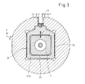
- the wall thickness of the preform over whose length can be varied as well as over its circumference is the nozzle body 7 in a plane perpendicular to the extrusion direction slidably mounted, in two perpendicular mutually extending axes x, y.
- the nozzle body 5 between the housing 3 and a nozzle retaining ring 21 for the purpose of sealing slightly clamped is effected via a two-part adjusting frame 17, in which the nozzle body 7 is guided.
- the adjusting frame 17 comprises a upstream of the extrudate arranged upper Stellrahmenteil 17a and a downstream of the extrudate arranged lower Stellrahmenteil 17 b, which together a cross slide guide form.
- the upper Stellrahmenteil 17a is via a first adjusting device 18 in the x-direction, as shown in FIG. 2 is apparent.
- the upper Stellrahmenteil 17a is in the x direction guided on the guide surface 22 in the nozzle holder ring 21.
- Of the Nozzle body 7 is located on the surfaces 23 of the upper Stellrahmenteils 17a, so that the nozzle body 7 a movement of the upper Stellrahmenteils 17a follows in the x direction. Formed in the y direction the upper Stellrahmenteil 17a with respect to the nozzle body. 7 a gap, so that the nozzle body 7 in the y-direction freedom of movement Has.
- the lower Stellrahmenteil is 17b adjustable via a second adjusting device 19 in the Y direction.
- the lower Stellrahmenteil 17 b is in the y direction to the Guiding surfaces 24 are guided in the nozzle holder ring 21.
- the nozzle body 7 is in the lower Stellrahmenteil 17b backlash against the surfaces 25, so that upon actuation of the second actuating device 19 in the y-direction of the nozzle body 7 of this movement follows.
- the nozzle body 7 in the lower actuator 17b game In the x direction, the nozzle body 7 in the lower actuator 17b game.
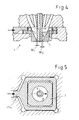
- the annular gap 11 on the one hand has a gap width W1 and on the diametrically opposite side arranged the gap width W2, with a continuous wall thickness increase from W1 to W2 of the ejected from the annular die 10 hose results.
- Extrusion head 1 also allows the sequential Extrusion of different materials and the main melt strand or the first melt strand, which is why in the drawing two annular flow channels 5 arranged concentrically to each other are.
- the extrusion device comprises two extruders, one extruder delivering the main melt stream, the other Extruder the additional melt stream. This second melt stream or melt strand becomes more flexible at times or in sections Hose line the movably mounted nozzle body. 7 fed.
- Annular gap 14 is provided in the nozzle body 7 upstream of the outlet opening concentrically arranged Annular gap 14 is provided. But it is also conceivable that several in the extrusion direction one above the other or with each other Ring gaps are provided.
- FIG. 6 shows a second exemplary embodiment of the invention Extrusion device shown.
- a solid line 26 is provided, which is rotatably connected to the nozzle body 7 is.
- a holding device 27 is provided, which by means of clamping flanges 30 are attached to a sliding plate 31.
- a ball bearing 29 is provided between the Sliding plate 31 and the bearing plate 28 a ball bearing 29 provided a relatively smooth shift this allows each other in the x-direction and in the y-direction.
- an opening 32 is provided in the bearing plate 28, through which a part of the holding device 27 and the Line between latch 20 and extruder 2 extend.
- the breakthrough 32 is sized so that through this extending holding device 27 has enough play.
Landscapes
- Engineering & Computer Science (AREA)
- Mechanical Engineering (AREA)
- Manufacturing & Machinery (AREA)
- Extrusion Moulding Of Plastics Or The Like (AREA)
- Blow-Moulding Or Thermoforming Of Plastics Or The Like (AREA)
- Processing And Handling Of Plastics And Other Materials For Molding In General (AREA)
Abstract
Description
- Fig. 1
- Eine schematische Teilansicht einer Extrusionseinrichtung gemäß der Erfindung, teilweise im Schnitt,
- Fig. 2
- Eine Schnittansicht entlang der Linien II/II Fig. 2,
- Fig. 3
- Eine Schnittansicht entlang der Linien III/III Fig. 1,
- Fig. 4
- Eine vergrößerte Schnittansicht des Düsenbereichs des in Fig. 1 dargestellten Extrusionkopfs,
- Fig. 5
- Einen Schnitt entlang der Linien V/V Fig. IV und
- Fig. 6
- Eine schematische Teilansicht einer Extrusionseinrichtung gemäß einem zweiten Ausführungsbeispiel der Erfindung, teilweise im Schnitt.
- 1
- Extrusionskopf
- 2
- Extruder
- 3
- Gehäuse
- 4
- Dorn
- 5
- Fließkanäle
- 6
- Düsenbereich
- 7
- Düsenkörper
- 8
- Austrittsöffnung
- 9
- Spitze
- 10
- Ringspaltdüse
- 11
- Ringspalt
- 12
- Schlauchleitung
- 13
- Ringkanal
- 14
- Ringspalt
- 15
- Ringraum
- 16
- Innenwandung
- 17
- Stellrahmen
- 17a
- oberer Stellrahmenteil
- 17b
- unterer Stellrahmenteil
- 18
- erste Stelleinrichtung
- 19
- zweite Stelleinrichtung
- 20
- Zwischenspeicher
- 21
- Düsenhaltering
- 22, 24
- Führungsflächen
- 23, 25
- Flächen
- 26
- feste Leitung
- 27
- Halteeinrichtung
- 28
- Lagerplatte
- 29
- Kugellagerung
- 30
- Klemmflansche
- 31
- Schiebeplatte
- 32
- Durchbruch
Claims (14)
- Verfahren zur Herstellung blasgeformter Hohlkörper aus thermoplastischem Kunststoff, bei welchem ein schlauchförmiger Vorformling aus einem Extrusionskopf mit verstellbarer Ringspaltdüse ausgestoßen wird und einer ersten Schicht thermoplastischen Materials in Extrusionsrichtung wenigstens abschnitts- bzw. zeitweise eine zweite Schicht thermoplastischen Materials konzentrisch aufgegeben wird und eine Einspeisung des zweiten Schmelzestrangs sowie eine Vereinigung der Schmelzestränge im Düsenbereich des Extrusionskopfs erfolgen, wobei während der Extrusion eine radiale Wanddickenvariation des mehrschichtigen Vorformlings mittels Düsenspaltverstellung in einer sich quer zur Extrusionsrichtung erstreckenden Ebene erfolgt.
- Verfahren nach Anspruch 1, dadurch gekennzeichnet, dass die Einspeisung des zweiten Schmelzestrangs in dem quer zur Extrusionsrichtung verstellbaren Bereich der Düse des Extrusionskopfs erfolgt.
- Verfahren nach einem der Ansprüche 1 oder 2, dadurch gekennzeichnet, dass Schmelzestränge etwa gleicher Materialbeschaffenheit coextrudiert werden.
- Verfahren nach einem der Ansprüche 1 -3, dadurch gekennzeichnet, dass die axiale und radiale Wanddickenverteilung des Vorformlings während der Extrusion unabhängig voneinander einstellbar sind.
- Verfahren nach einem der Ansprüche 1-4, dadurch gekennzeichnet, dass die axiale und/oder radiale Wanddickenverteilung des Vorformlings nach einem vorgegebenen, produktspezifisch erstellten Programm erfolgt.
- Verfahren nach einem der Ansprüche 1-5, gekennzeichnet durch die Volumenstromvariation der Schmelzestränge während der Extrusion.
- Extrusionseinrichtung, insbesondere zur Durchführung des Verfahrens nach Anspruch 1, mit einem Gehäuse (3), mit einem Dorn (4), wobei Gehäuse (3) und Dorn (4) relativ zueinander axial verstellbar sind, mit wenigstens einem einen Düsenbereich bildenden Düsenkörper (7), dessen Austrittsöffnung (8) mit dem Dorn (4) eine Ringspaltdüse (10) bildet, mit Mitteln zur Zuführung eines zweiten zu einem ersten Schmelzestrang konzentrischen Schmelzestrangs in dem Düsenbereich sowie mit Mitteln zur Verstellung der Lage des Dorns (4) und der Austrittsöffnung (8) des Düsenkörpers (7) zueinander in einer sich quer zur Extrusionsrichtung erstreckenden Ebene.
- Extrusionseinrichtung nach Anspruch 7, dadurch gekennzeichnet, dass zur Einspeisung des zweiten Schmelzestrangs ein zweiter Extruder (2) vorgesehen ist, der über eine Zufuhrleitung mit dem Düsenkörper (7) verbunden ist.
- Extrusionseinrichtung nach einem der Ansprüche 7 oder 8, dadurch gekennzeichnet dass der Düsenkörper (7) bezüglich des Dorns (4) während der Extrusion dezentrierbar ist.
- Extrusionseinrichtung nach einem der Ansprüche 8 oder 9, dadurch gekennzeichnet dass die Zufuhrleitung flexibel ist.
- Extrusionseinrichtung nach einem der Ansprüche 8 bis 10, dadurch gekennzeichnet, dass in der Zufuhrleitung ein Zwischenspeicher (20) vorgesehen ist.
- Extrusionseinrichtung nach einem der Ansprüche 7 bis 11, dadurch gekennzeichnet dass für die Zufuhr des zweiten Schmelzestrangs in dem Düsenkörper (7) ein stromaufwärts der Ringspaltdüse (10) angeordneter umlaufender Ringspalt (14) vorgesehen ist.
- Extrusionseinrichtung nach einem der Ansprüche 7 bis 12, dadurch gekennzeichnet dass der Düsenkörper (7) in einer sich quer zur Extrusionsrichtung erstreckenden Ebene in zwei sich zueinander senkrecht erstreckenden Achsen x,y verschieblich gelagert ist.
- Extrusionseinrichtung nach einem der Ansprüche 7 bis 9, dadurch gekennzeichnet, dass der zweite Extruder (2) in einer sich etwa parallel zur Extrusionsrichtung erstreckenden Ebene beweglich bezüglich des Extrusionskopfes (1) und an diesem gelagert ist, derart, dass dieser eine etwaige Verstellbewegung des Düsenkörpers nachvollziehen kann.
Applications Claiming Priority (2)
| Application Number | Priority Date | Filing Date | Title |
|---|---|---|---|
| DE10237051A DE10237051A1 (de) | 2002-08-09 | 2002-08-09 | Verfahren und Vorrichtung zur Herstellung blasgeformter Hohlkörper aus thermoplastischen Kunststoffen |
| DE10237051 | 2002-08-09 |
Publications (2)
| Publication Number | Publication Date |
|---|---|
| EP1388406A1 true EP1388406A1 (de) | 2004-02-11 |
| EP1388406B1 EP1388406B1 (de) | 2005-10-19 |
Family
ID=30128835
Family Applications (1)
| Application Number | Title | Priority Date | Filing Date |
|---|---|---|---|
| EP03017813A Expired - Lifetime EP1388406B1 (de) | 2002-08-09 | 2003-08-05 | Verfahren und Vorrichtung zur Herstellung blasgeformter Hohlkörper aus thermoplastischen Kunststoffen |
Country Status (4)
| Country | Link |
|---|---|
| EP (1) | EP1388406B1 (de) |
| AT (1) | ATE307018T1 (de) |
| DE (2) | DE10237051A1 (de) |
| ES (1) | ES2251654T3 (de) |
Cited By (4)
| Publication number | Priority date | Publication date | Assignee | Title |
|---|---|---|---|---|
| WO2015175208A1 (en) * | 2014-05-15 | 2015-11-19 | Dow Global Technologies Llc | System, method and apparatus for producing a multi-layer, annular microcapillary product |
| CN111633944A (zh) * | 2020-06-30 | 2020-09-08 | 苏州同大机械有限公司 | 熔坯径向壁厚可调的模头结构 |
| US20220143889A1 (en) * | 2020-11-12 | 2022-05-12 | Promix Solutions Ag | Annular nozzle |
| CN116135515A (zh) * | 2021-11-18 | 2023-05-19 | 厦门科炬源自动化设备有限公司 | 一种全自动内胎挤出机机头 |
Families Citing this family (1)
| Publication number | Priority date | Publication date | Assignee | Title |
|---|---|---|---|---|
| DE102020125261B3 (de) | 2020-09-28 | 2021-10-07 | Troester Gmbh & Co. Kg | Extrusionskopf und Verfahren zur Herstellung eines länglichen Hohlkörpers mittels dieses Extrusionskopfs |
Citations (4)
| Publication number | Priority date | Publication date | Assignee | Title |
|---|---|---|---|---|
| US4472129A (en) * | 1981-04-09 | 1984-09-18 | Compagnie Francaise De Raffinage | Head for extrusion of a tubular parison formed of at least one layer of material |
| US5156857A (en) * | 1988-11-23 | 1992-10-20 | American National Can Company | Extrusion die for extrusion blow molding equipment |
| EP0740994A1 (de) * | 1995-05-05 | 1996-11-06 | Graham Engineering Corporation | Presskopf mit verstellbarer Dorneinheit und Verfahren |
| US6214268B1 (en) * | 1997-02-18 | 2001-04-10 | Tigers Polymer Corporation | Blow-molded hoses and apparatuses for producing the same |
Family Cites Families (3)
| Publication number | Priority date | Publication date | Assignee | Title |
|---|---|---|---|---|
| DE3516470A1 (de) * | 1985-05-08 | 1986-11-13 | Basf Ag, 6700 Ludwigshafen | Verfahren und vorrichtung zur herstellung blasgeformter hohlkoerper aus thermoplastischen kunststoffen |
| DE19537132C2 (de) * | 1995-10-05 | 2003-08-07 | Mbk Maschb Koetke Gmbh | Blaskopf mit verstellbarer Düse |
| DE29910288U1 (de) * | 1998-03-05 | 1999-08-05 | Mauser-Werke GmbH, 50321 Brühl | Extrusionskopf |
-
2002
- 2002-08-09 DE DE10237051A patent/DE10237051A1/de not_active Ceased
-
2003
- 2003-08-05 DE DE50301397T patent/DE50301397D1/de not_active Expired - Lifetime
- 2003-08-05 AT AT03017813T patent/ATE307018T1/de active
- 2003-08-05 ES ES03017813T patent/ES2251654T3/es not_active Expired - Lifetime
- 2003-08-05 EP EP03017813A patent/EP1388406B1/de not_active Expired - Lifetime
Patent Citations (4)
| Publication number | Priority date | Publication date | Assignee | Title |
|---|---|---|---|---|
| US4472129A (en) * | 1981-04-09 | 1984-09-18 | Compagnie Francaise De Raffinage | Head for extrusion of a tubular parison formed of at least one layer of material |
| US5156857A (en) * | 1988-11-23 | 1992-10-20 | American National Can Company | Extrusion die for extrusion blow molding equipment |
| EP0740994A1 (de) * | 1995-05-05 | 1996-11-06 | Graham Engineering Corporation | Presskopf mit verstellbarer Dorneinheit und Verfahren |
| US6214268B1 (en) * | 1997-02-18 | 2001-04-10 | Tigers Polymer Corporation | Blow-molded hoses and apparatuses for producing the same |
Cited By (5)
| Publication number | Priority date | Publication date | Assignee | Title |
|---|---|---|---|---|
| WO2015175208A1 (en) * | 2014-05-15 | 2015-11-19 | Dow Global Technologies Llc | System, method and apparatus for producing a multi-layer, annular microcapillary product |
| CN106687277A (zh) * | 2014-05-15 | 2017-05-17 | 陶氏环球技术有限责任公司 | 用于制备多层、环状微毛细管产物的系统、方法和设备 |
| CN111633944A (zh) * | 2020-06-30 | 2020-09-08 | 苏州同大机械有限公司 | 熔坯径向壁厚可调的模头结构 |
| US20220143889A1 (en) * | 2020-11-12 | 2022-05-12 | Promix Solutions Ag | Annular nozzle |
| CN116135515A (zh) * | 2021-11-18 | 2023-05-19 | 厦门科炬源自动化设备有限公司 | 一种全自动内胎挤出机机头 |
Also Published As
| Publication number | Publication date |
|---|---|
| ES2251654T3 (es) | 2006-05-01 |
| ATE307018T1 (de) | 2005-11-15 |
| DE10237051A1 (de) | 2004-02-26 |
| EP1388406B1 (de) | 2005-10-19 |
| DE50301397D1 (de) | 2006-03-02 |
Similar Documents
| Publication | Publication Date | Title |
|---|---|---|
| EP0995579B1 (de) | Verfahren zur fortlaufenden Herstellung eines Verbundrohres mit einer Rohr-Muffe und Vorrichtung zur Durchführung des Verfahrens | |
| EP0326584B1 (de) | Verfahren und vorrichtung zur herstellung grossvolumiger hohlkörper aus kunststoff mit mehrschichtigen wandungen | |
| DE3718605C2 (de) | ||
| EP1944150B1 (de) | Saugblasformwerkzeug zum Herstellen von extrusions-saugblasgeformten Kunststoff-Formteilen, Herstellungsverfahren und Verwendung | |
| EP1183145B1 (de) | Vorrichtung zum herstellen von extrusionsblasgeformten behältern mit mindestens zwei kammern | |
| DE102013105749B4 (de) | Extrusionsschlauchkopf für diskontinuierliches Schäumen | |
| DE69516617T2 (de) | Vorrichtung und Verfahren zum Blasformen von dreidimensionalen Gegenständen | |
| EP2148773B1 (de) | Vorrichtung und verfahren zur herstellung von kunststoffgegenständen durch extrusionsblasformen | |
| DE3439285A1 (de) | Verfahren und vorrichtung zum herstellen eines hohlen kunststoffkoerpers | |
| EP0349872B1 (de) | Verfahren und Vorrichtung zum Herstellen von Hohlkörpern aus thermoplastischen Kunstoffen | |
| DE202007002954U1 (de) | Vorrichtung zur fortlaufenden Herstellung eines Verbundrohres mit Rohrmuffe | |
| EP1388406B1 (de) | Verfahren und Vorrichtung zur Herstellung blasgeformter Hohlkörper aus thermoplastischen Kunststoffen | |
| DE3044535A1 (de) | Verfahren und vorrichtung zur herstellung mehrschichtiger kunststoffprofile, insbesondere kunststoffrohre | |
| DE2703454A1 (de) | Verfahren und vorrichtung zum blasformen | |
| EP0923445A1 (de) | Fassartiger behälter aus kunststoff sowie verfahren und vorrichtung zu seiner herstellung | |
| EP1698445B1 (de) | Verfahren zum Blasformen von Hohlkörpern aus thermoplatischem Kunststoff | |
| DE4135336C2 (de) | Verfahren zum Strangpressen von Mehrschichtrohren | |
| DE3636960C2 (de) | Vorrichtung und Verfahren zur Herstellung eines schlauchartigen, extrudierten Produktes | |
| EP0228616A2 (de) | Verfahren und Vorrichtung zum Herstellen von Hohlkörpern aus thermoplastischen Kunststoffen | |
| EP1129838B1 (de) | Vorrichtung zum Herstellen von hohlkörperförmigen Artikeln aus thermoplastischem Kunststoff durch Saugblasen | |
| DE102021118705A1 (de) | Vorrichtung und Verfahren für die biaxiale Kunststoff-Extrusion | |
| EP2225083A1 (de) | Schlauchförmiger vorformling und verfahren sowie vorrichtung zur herstellung des vorformlings | |
| EP2236267A1 (de) | Verfahren und Vorrichtung zur Herstellung eines Kunststoffbauteils sowie Kunststoffbauteil | |
| DE19851076A1 (de) | Verfahren und Vorrichtung zur Herstellung eines Zusatzteils für ein technisches Formteil | |
| DE2445566A1 (de) | Verfahren und geraet zur behandlung der aeusseren und inneren oberflaeche eines stranggepressten rohres aus thermoplastischem, harzartigem material |
Legal Events
| Date | Code | Title | Description |
|---|---|---|---|
| PUAI | Public reference made under article 153(3) epc to a published international application that has entered the european phase |
Free format text: ORIGINAL CODE: 0009012 |
|
| AK | Designated contracting states |
Kind code of ref document: A1 Designated state(s): AT BE BG CH CY CZ DE DK EE ES FI FR GB GR HU IE IT LI LU MC NL PT RO SE SI SK TR |
|
| AX | Request for extension of the european patent |
Extension state: AL LT LV MK |
|
| 17P | Request for examination filed |
Effective date: 20040420 |
|
| 17Q | First examination report despatched |
Effective date: 20040802 |
|
| AKX | Designation fees paid |
Designated state(s): AT BE BG CH CY CZ DE DK EE ES FI FR GB GR HU IE IT LI LU MC NL PT RO SE SI SK TR |
|
| RAP1 | Party data changed (applicant data changed or rights of an application transferred) |
Owner name: KAUTEX MASCHINENBAU GMBH |
|
| GRAP | Despatch of communication of intention to grant a patent |
Free format text: ORIGINAL CODE: EPIDOSNIGR1 |
|
| GRAS | Grant fee paid |
Free format text: ORIGINAL CODE: EPIDOSNIGR3 |
|
| GRAA | (expected) grant |
Free format text: ORIGINAL CODE: 0009210 |
|
| AK | Designated contracting states |
Kind code of ref document: B1 Designated state(s): AT BE BG CH CY CZ DE DK EE ES FI FR GB GR HU IE IT LI LU MC NL PT RO SE SI SK TR |
|
| PG25 | Lapsed in a contracting state [announced via postgrant information from national office to epo] |
Ref country code: FI Free format text: LAPSE BECAUSE OF FAILURE TO SUBMIT A TRANSLATION OF THE DESCRIPTION OR TO PAY THE FEE WITHIN THE PRESCRIBED TIME-LIMIT Effective date: 20051019 Ref country code: RO Free format text: LAPSE BECAUSE OF FAILURE TO SUBMIT A TRANSLATION OF THE DESCRIPTION OR TO PAY THE FEE WITHIN THE PRESCRIBED TIME-LIMIT Effective date: 20051019 Ref country code: NL Free format text: LAPSE BECAUSE OF FAILURE TO SUBMIT A TRANSLATION OF THE DESCRIPTION OR TO PAY THE FEE WITHIN THE PRESCRIBED TIME-LIMIT Effective date: 20051019 Ref country code: IE Free format text: LAPSE BECAUSE OF FAILURE TO SUBMIT A TRANSLATION OF THE DESCRIPTION OR TO PAY THE FEE WITHIN THE PRESCRIBED TIME-LIMIT Effective date: 20051019 Ref country code: SK Free format text: LAPSE BECAUSE OF FAILURE TO SUBMIT A TRANSLATION OF THE DESCRIPTION OR TO PAY THE FEE WITHIN THE PRESCRIBED TIME-LIMIT Effective date: 20051019 Ref country code: SI Free format text: LAPSE BECAUSE OF FAILURE TO SUBMIT A TRANSLATION OF THE DESCRIPTION OR TO PAY THE FEE WITHIN THE PRESCRIBED TIME-LIMIT Effective date: 20051019 Ref country code: CZ Free format text: LAPSE BECAUSE OF FAILURE TO SUBMIT A TRANSLATION OF THE DESCRIPTION OR TO PAY THE FEE WITHIN THE PRESCRIBED TIME-LIMIT Effective date: 20051019 Ref country code: GB Free format text: LAPSE BECAUSE OF FAILURE TO SUBMIT A TRANSLATION OF THE DESCRIPTION OR TO PAY THE FEE WITHIN THE PRESCRIBED TIME-LIMIT Effective date: 20051019 |
|
| REG | Reference to a national code |
Ref country code: GB Ref legal event code: FG4D Free format text: NOT ENGLISH |
|
| REG | Reference to a national code |
Ref country code: CH Ref legal event code: EP |
|
| REG | Reference to a national code |
Ref country code: IE Ref legal event code: FG4D Free format text: LANGUAGE OF EP DOCUMENT: GERMAN |
|
| PG25 | Lapsed in a contracting state [announced via postgrant information from national office to epo] |
Ref country code: DK Free format text: LAPSE BECAUSE OF FAILURE TO SUBMIT A TRANSLATION OF THE DESCRIPTION OR TO PAY THE FEE WITHIN THE PRESCRIBED TIME-LIMIT Effective date: 20060119 Ref country code: GR Free format text: LAPSE BECAUSE OF FAILURE TO SUBMIT A TRANSLATION OF THE DESCRIPTION OR TO PAY THE FEE WITHIN THE PRESCRIBED TIME-LIMIT Effective date: 20060119 Ref country code: SE Free format text: LAPSE BECAUSE OF FAILURE TO SUBMIT A TRANSLATION OF THE DESCRIPTION OR TO PAY THE FEE WITHIN THE PRESCRIBED TIME-LIMIT Effective date: 20060119 Ref country code: BG Free format text: LAPSE BECAUSE OF FAILURE TO SUBMIT A TRANSLATION OF THE DESCRIPTION OR TO PAY THE FEE WITHIN THE PRESCRIBED TIME-LIMIT Effective date: 20060119 |
|
| REF | Corresponds to: |
Ref document number: 50301397 Country of ref document: DE Date of ref document: 20060302 Kind code of ref document: P |
|
| PG25 | Lapsed in a contracting state [announced via postgrant information from national office to epo] |
Ref country code: PT Free format text: LAPSE BECAUSE OF FAILURE TO SUBMIT A TRANSLATION OF THE DESCRIPTION OR TO PAY THE FEE WITHIN THE PRESCRIBED TIME-LIMIT Effective date: 20060320 |
|
| NLV1 | Nl: lapsed or annulled due to failure to fulfill the requirements of art. 29p and 29m of the patents act | ||
| PG25 | Lapsed in a contracting state [announced via postgrant information from national office to epo] |
Ref country code: HU Free format text: LAPSE BECAUSE OF FAILURE TO SUBMIT A TRANSLATION OF THE DESCRIPTION OR TO PAY THE FEE WITHIN THE PRESCRIBED TIME-LIMIT Effective date: 20060420 |
|
| REG | Reference to a national code |
Ref country code: ES Ref legal event code: FG2A Ref document number: 2251654 Country of ref document: ES Kind code of ref document: T3 |
|
| GBV | Gb: ep patent (uk) treated as always having been void in accordance with gb section 77(7)/1977 [no translation filed] |
Effective date: 20051019 |
|
| REG | Reference to a national code |
Ref country code: IE Ref legal event code: FD4D |
|
| PLBI | Opposition filed |
Free format text: ORIGINAL CODE: 0009260 |
|
| PLAX | Notice of opposition and request to file observation + time limit sent |
Free format text: ORIGINAL CODE: EPIDOSNOBS2 |
|
| 26 | Opposition filed |
Opponent name: SCHUETZ GMBH & CO. KGAA Effective date: 20060717 |
|
| PG25 | Lapsed in a contracting state [announced via postgrant information from national office to epo] |
Ref country code: BE Free format text: LAPSE BECAUSE OF NON-PAYMENT OF DUE FEES Effective date: 20060831 Ref country code: MC Free format text: LAPSE BECAUSE OF NON-PAYMENT OF DUE FEES Effective date: 20060831 |
|
| EN | Fr: translation not filed | ||
| PG25 | Lapsed in a contracting state [announced via postgrant information from national office to epo] |
Ref country code: FR Free format text: LAPSE BECAUSE OF FAILURE TO SUBMIT A TRANSLATION OF THE DESCRIPTION OR TO PAY THE FEE WITHIN THE PRESCRIBED TIME-LIMIT Effective date: 20061208 |
|
| PLAF | Information modified related to communication of a notice of opposition and request to file observations + time limit |
Free format text: ORIGINAL CODE: EPIDOSCOBS2 |
|
| PLBB | Reply of patent proprietor to notice(s) of opposition received |
Free format text: ORIGINAL CODE: EPIDOSNOBS3 |
|
| BERE | Be: lapsed |
Owner name: KAUTEX MASCHINENBAU G.M.B.H. Effective date: 20060831 |
|
| PLCK | Communication despatched that opposition was rejected |
Free format text: ORIGINAL CODE: EPIDOSNREJ1 |
|
| RDAE | Information deleted related to despatch of communication that patent is revoked |
Free format text: ORIGINAL CODE: EPIDOSDREV1 |
|
| RDAF | Communication despatched that patent is revoked |
Free format text: ORIGINAL CODE: EPIDOSNREV1 |
|
| REG | Reference to a national code |
Ref country code: CH Ref legal event code: PL |
|
| PG25 | Lapsed in a contracting state [announced via postgrant information from national office to epo] |
Ref country code: LI Free format text: LAPSE BECAUSE OF NON-PAYMENT OF DUE FEES Effective date: 20070831 Ref country code: CH Free format text: LAPSE BECAUSE OF NON-PAYMENT OF DUE FEES Effective date: 20070831 |
|
| PLBN | Opposition rejected |
Free format text: ORIGINAL CODE: 0009273 |
|
| STAA | Information on the status of an ep patent application or granted ep patent |
Free format text: STATUS: OPPOSITION REJECTED |
|
| 27O | Opposition rejected |
Effective date: 20080209 |
|
| PG25 | Lapsed in a contracting state [announced via postgrant information from national office to epo] |
Ref country code: EE Free format text: LAPSE BECAUSE OF FAILURE TO SUBMIT A TRANSLATION OF THE DESCRIPTION OR TO PAY THE FEE WITHIN THE PRESCRIBED TIME-LIMIT Effective date: 20051019 |
|
| PG25 | Lapsed in a contracting state [announced via postgrant information from national office to epo] |
Ref country code: LU Free format text: LAPSE BECAUSE OF NON-PAYMENT OF DUE FEES Effective date: 20060805 Ref country code: TR Free format text: LAPSE BECAUSE OF FAILURE TO SUBMIT A TRANSLATION OF THE DESCRIPTION OR TO PAY THE FEE WITHIN THE PRESCRIBED TIME-LIMIT Effective date: 20051019 |
|
| PG25 | Lapsed in a contracting state [announced via postgrant information from national office to epo] |
Ref country code: FR Free format text: LAPSE BECAUSE OF FAILURE TO SUBMIT A TRANSLATION OF THE DESCRIPTION OR TO PAY THE FEE WITHIN THE PRESCRIBED TIME-LIMIT Effective date: 20051019 Ref country code: CY Free format text: LAPSE BECAUSE OF FAILURE TO SUBMIT A TRANSLATION OF THE DESCRIPTION OR TO PAY THE FEE WITHIN THE PRESCRIBED TIME-LIMIT Effective date: 20051019 |
|
| REG | Reference to a national code |
Ref country code: DE Ref legal event code: R082 Ref document number: 50301397 Country of ref document: DE Representative=s name: FLEISCHER, GODEMEYER, KIERDORF & PARTNER, PATE, DE Ref country code: DE Ref legal event code: R082 Ref document number: 50301397 Country of ref document: DE Representative=s name: KIERDORF RITSCHEL PATENTANWAELTE PARTG MBB, DE Ref country code: DE Ref legal event code: R082 Ref document number: 50301397 Country of ref document: DE Representative=s name: KIERDORF RITSCHEL RICHLY PATENTANWAELTE PARTG , DE Ref country code: DE Ref legal event code: R082 Ref document number: 50301397 Country of ref document: DE Representative=s name: RICHLY & RITSCHEL PATENTANWAELTE PARTG MBB, DE |
|
| REG | Reference to a national code |
Ref country code: DE Ref legal event code: R082 Ref document number: 50301397 Country of ref document: DE Representative=s name: KIERDORF RITSCHEL PATENTANWAELTE PARTG MBB, DE Ref country code: DE Ref legal event code: R082 Ref document number: 50301397 Country of ref document: DE Representative=s name: KIERDORF RITSCHEL RICHLY PATENTANWAELTE PARTG , DE Ref country code: DE Ref legal event code: R082 Ref document number: 50301397 Country of ref document: DE Representative=s name: RICHLY & RITSCHEL PATENTANWAELTE PARTG MBB, DE |
|
| PGFP | Annual fee paid to national office [announced via postgrant information from national office to epo] |
Ref country code: ES Payment date: 20170901 Year of fee payment: 15 |
|
| REG | Reference to a national code |
Ref country code: DE Ref legal event code: R079 Ref document number: 50301397 Country of ref document: DE Free format text: PREVIOUS MAIN CLASS: B29C0047220000 Ipc: B29C0048325000 |
|
| REG | Reference to a national code |
Ref country code: ES Ref legal event code: FD2A Effective date: 20190918 |
|
| PG25 | Lapsed in a contracting state [announced via postgrant information from national office to epo] |
Ref country code: ES Free format text: LAPSE BECAUSE OF NON-PAYMENT OF DUE FEES Effective date: 20180806 |
|
| PGFP | Annual fee paid to national office [announced via postgrant information from national office to epo] |
Ref country code: DE Payment date: 20190822 Year of fee payment: 17 Ref country code: IT Payment date: 20190821 Year of fee payment: 17 |
|
| PGFP | Annual fee paid to national office [announced via postgrant information from national office to epo] |
Ref country code: AT Payment date: 20190820 Year of fee payment: 17 |
|
| REG | Reference to a national code |
Ref country code: DE Ref legal event code: R119 Ref document number: 50301397 Country of ref document: DE |
|
| REG | Reference to a national code |
Ref country code: AT Ref legal event code: MM01 Ref document number: 307018 Country of ref document: AT Kind code of ref document: T Effective date: 20200805 |
|
| PG25 | Lapsed in a contracting state [announced via postgrant information from national office to epo] |
Ref country code: AT Free format text: LAPSE BECAUSE OF NON-PAYMENT OF DUE FEES Effective date: 20200805 |
|
| PG25 | Lapsed in a contracting state [announced via postgrant information from national office to epo] |
Ref country code: DE Free format text: LAPSE BECAUSE OF NON-PAYMENT OF DUE FEES Effective date: 20210302 |
|
| PG25 | Lapsed in a contracting state [announced via postgrant information from national office to epo] |
Ref country code: IT Free format text: LAPSE BECAUSE OF NON-PAYMENT OF DUE FEES Effective date: 20200805 |