EP1387502A1 - Récepteur portable à dispersion réduite - Google Patents
Récepteur portable à dispersion réduite Download PDFInfo
- Publication number
- EP1387502A1 EP1387502A1 EP02078252A EP02078252A EP1387502A1 EP 1387502 A1 EP1387502 A1 EP 1387502A1 EP 02078252 A EP02078252 A EP 02078252A EP 02078252 A EP02078252 A EP 02078252A EP 1387502 A1 EP1387502 A1 EP 1387502A1
- Authority
- EP
- European Patent Office
- Prior art keywords
- signals
- antennas
- signal
- output
- phase
- Prior art date
- Legal status (The legal status is an assumption and is not a legal conclusion. Google has not performed a legal analysis and makes no representation as to the accuracy of the status listed.)
- Granted
Links
- 239000006185 dispersion Substances 0.000 title description 17
- 238000001914 filtration Methods 0.000 claims description 5
- 239000003990 capacitor Substances 0.000 description 4
- 230000003071 parasitic effect Effects 0.000 description 4
- 230000008901 benefit Effects 0.000 description 3
- 241001442234 Cosa Species 0.000 description 2
- 244000089409 Erythrina poeppigiana Species 0.000 description 2
- 235000009776 Rathbunia alamosensis Nutrition 0.000 description 2
- 230000003321 amplification Effects 0.000 description 2
- 238000001514 detection method Methods 0.000 description 2
- 230000000694 effects Effects 0.000 description 2
- 238000003199 nucleic acid amplification method Methods 0.000 description 2
- 230000010363 phase shift Effects 0.000 description 2
- 230000035945 sensitivity Effects 0.000 description 1
Images

Classifications
-
- H—ELECTRICITY
- H04—ELECTRIC COMMUNICATION TECHNIQUE
- H04B—TRANSMISSION
- H04B7/00—Radio transmission systems, i.e. using radiation field
- H04B7/02—Diversity systems; Multi-antenna system, i.e. transmission or reception using multiple antennas
- H04B7/04—Diversity systems; Multi-antenna system, i.e. transmission or reception using multiple antennas using two or more spaced independent antennas
- H04B7/08—Diversity systems; Multi-antenna system, i.e. transmission or reception using multiple antennas using two or more spaced independent antennas at the receiving station
- H04B7/0868—Hybrid systems, i.e. switching and combining
- H04B7/0874—Hybrid systems, i.e. switching and combining using subgroups of receive antennas
-
- H—ELECTRICITY
- H04—ELECTRIC COMMUNICATION TECHNIQUE
- H04B—TRANSMISSION
- H04B7/00—Radio transmission systems, i.e. using radiation field
- H04B7/02—Diversity systems; Multi-antenna system, i.e. transmission or reception using multiple antennas
- H04B7/04—Diversity systems; Multi-antenna system, i.e. transmission or reception using multiple antennas using two or more spaced independent antennas
- H04B7/08—Diversity systems; Multi-antenna system, i.e. transmission or reception using multiple antennas using two or more spaced independent antennas at the receiving station
- H04B7/0837—Diversity systems; Multi-antenna system, i.e. transmission or reception using multiple antennas using two or more spaced independent antennas at the receiving station using pre-detection combining
- H04B7/084—Equal gain combining, only phase adjustments
-
- H—ELECTRICITY
- H04—ELECTRIC COMMUNICATION TECHNIQUE
- H04B—TRANSMISSION
- H04B7/00—Radio transmission systems, i.e. using radiation field
- H04B7/02—Diversity systems; Multi-antenna system, i.e. transmission or reception using multiple antennas
- H04B7/04—Diversity systems; Multi-antenna system, i.e. transmission or reception using multiple antennas using two or more spaced independent antennas
- H04B7/08—Diversity systems; Multi-antenna system, i.e. transmission or reception using multiple antennas using two or more spaced independent antennas at the receiving station
- H04B7/0802—Diversity systems; Multi-antenna system, i.e. transmission or reception using multiple antennas using two or more spaced independent antennas at the receiving station using antenna selection
- H04B7/0805—Diversity systems; Multi-antenna system, i.e. transmission or reception using multiple antennas using two or more spaced independent antennas at the receiving station using antenna selection with single receiver and antenna switching
- H04B7/0808—Diversity systems; Multi-antenna system, i.e. transmission or reception using multiple antennas using two or more spaced independent antennas at the receiving station using antenna selection with single receiver and antenna switching comparing all antennas before reception
-
- H—ELECTRICITY
- H04—ELECTRIC COMMUNICATION TECHNIQUE
- H04B—TRANSMISSION
- H04B7/00—Radio transmission systems, i.e. using radiation field
- H04B7/02—Diversity systems; Multi-antenna system, i.e. transmission or reception using multiple antennas
- H04B7/04—Diversity systems; Multi-antenna system, i.e. transmission or reception using multiple antennas using two or more spaced independent antennas
- H04B7/08—Diversity systems; Multi-antenna system, i.e. transmission or reception using multiple antennas using two or more spaced independent antennas at the receiving station
- H04B7/0802—Diversity systems; Multi-antenna system, i.e. transmission or reception using multiple antennas using two or more spaced independent antennas at the receiving station using antenna selection
- H04B7/0805—Diversity systems; Multi-antenna system, i.e. transmission or reception using multiple antennas using two or more spaced independent antennas at the receiving station using antenna selection with single receiver and antenna switching
- H04B7/0814—Diversity systems; Multi-antenna system, i.e. transmission or reception using multiple antennas using two or more spaced independent antennas at the receiving station using antenna selection with single receiver and antenna switching based on current reception conditions, e.g. switching to different antenna when signal level is below threshold
-
- H—ELECTRICITY
- H04—ELECTRIC COMMUNICATION TECHNIQUE
- H04B—TRANSMISSION
- H04B7/00—Radio transmission systems, i.e. using radiation field
- H04B7/02—Diversity systems; Multi-antenna system, i.e. transmission or reception using multiple antennas
- H04B7/04—Diversity systems; Multi-antenna system, i.e. transmission or reception using multiple antennas using two or more spaced independent antennas
- H04B7/08—Diversity systems; Multi-antenna system, i.e. transmission or reception using multiple antennas using two or more spaced independent antennas at the receiving station
- H04B7/0837—Diversity systems; Multi-antenna system, i.e. transmission or reception using multiple antennas using two or more spaced independent antennas at the receiving station using pre-detection combining
- H04B7/0842—Weighted combining
Definitions
- the present invention relates to a portable receiver intended in particular for applications in the automotive industry, for example for remote opening of a vehicle, and more generally to applications for contactless detection.
- the portable receiver comprises a first reception stage comprising three antennas oriented to form a substantially orthogonal reference, and likely to receive an external signal in a given frequency range, a second stage of processing of the signals delivered at the output of the antennas, and a third stage of selection of one of the signals delivered at the output of the stage of processing or a third stage of combination of the signals delivered at the output of the treatment stage.
- the signals V4, V5 and V6 differ from the signals V1, V2 and V3 only in that it introduces a gain factor G of the amplifiers placed at the output of the antennas.
- Such a receiver nevertheless has some disadvantages.
- Receiving holes an orientation of the portable receiver, for example a key of a motor vehicle, in relation to the transmitter, for example the vehicle automobile, that the portable receiver receives no signal and almost regardless of the distance between the transmitter and the receiver.
- dispersion or dispersion zone means the spatial area in which the reception of the transmitter signals depends on the orientation of the receiver report to the issuer.
- the dispersion factor is defined by the extremes of the amplitude of the signal delivered at the output of the adder or the means for selecting the receiver.
- the maximum amplitude is equivalent to the amplitude from the external signal, to a near gain factor introduced by the amplifiers.
- the output signal has a minimum amplitude for each receiving hole.
- the amplitude is zero. So the factor of dispersion ranges between 0 and 1. Throughout the issuing area of the transmitter in the receiver is supposed to work, the effective reception will therefore depend on the orientation of the receiver relative to the transmitter.
- the receiver uses signal selection means having the largest amplitude.
- the solution according to this second embodiment therefore has a factor dispersion range between 1 / ⁇ 3 and 1.
- the dispersion is therefore of the order of 42%, which may to some extent be a disadvantage for reasons of security or convenience of use.
- the selection means receive three among which is selected the one having the greatest amplitude, which requires a relatively complex treatment.
- the means of selection must firstly know the amplitude of the three signals V4, V5 and V6, and secondly compare the three signals two by two, the selection can only take place once all these operations performed.
- the receiver does comprises only two antennas, and therefore only receives the external signals in the plane formed by these two antennas. This receiver therefore only allows to receive next two directions, the third direction corresponding to a receiving hole.
- the solution presented in this document does not take into account the subtractor 15 placed at the output of the phase-shifter circuits 13 and 14, or the specific characteristics of the antennas 11 and 12, which causes the disregard of the desired phase shifts and thereby even no longer assures the desired amplitude stability.
- the present invention therefore proposes to overcome the disadvantages mentioned above by providing a portable receiver with reduced dispersion while by consuming a minimum of energy.
- the portable receiver according to the invention in the case of a third selection stage, in addition to satisfying the definition given in the introduction to the description is characterized in that said second treatment stage comprises first and second phase shifters connected at the output of two of said antennas, said signals delivered at the output of these two antennas being out of phase with an angle of ⁇ / 2 or 3 ⁇ / 2 with respect to each other, and means for combining said signals phase shifted forming a first signal delivered to said third selection stage, that said signal delivered by the third antenna corresponds to a second delivered signal third auditing stage, and in that said third selection stage comprises means for selecting from said two output signals said second stage, either the signal having the greatest amplitude, or one of the two signals having an amplitude greater than a reference amplitude, arbitrarily one of the two signals if they have the same amplitude.
- the portable receiver according to the invention in addition to that it satisfies the given definition in the introduction to the description, is characterized in that said second stage of processing comprises first and second phase shifters connected at the output of two of said antennas, said signals delivered at the output of these two antennas being out of phase with an angle of ⁇ / 2 or 3 ⁇ / 2 relative to each other, and means for combining said phase-shifted signals forming a first combined signal supplied into input of first elevator means squared, in that said second stage of treatment furthermore includes correcting means for correcting the attenuation introduced by the first and second phase shifters in series with second means elevators squared, and in that said third combination stage comprises a adder receiving as input the signals at the output of said first and second elevator means squared.
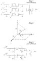
- the receiver comprises three antennas 1, 2 and 3 forming an orthogonal reference.
- phase shifters 4 and 5 for example RC and CR phase shifters, for phase shifted signals V1 and V2 delivered by these antennas.
- the two out-of-phase signals V4 and V5 are provided at the input of an adder 6, or of a subtracter, according to the direction of orientation of the antennas.
- the signal V12 delivered at the output of the adder 6, or the subtractor must have a substantially constant amplitude, which makes it possible to have no dispersion in the plane formed by these two antennas 1 and 2. It has been highlighted , in the context of the European patent application No.
- Rcor (Rant * Req) / (Req - Rant), where Rant is the internal resistance of the corresponding antenna, where Req is the equivalent resistance of the phase-shifting circuit corresponding, Req being greater than or equal to Rant.
- Correction capacitors may also be provided, the capacitors of the two correction capacitors being given by the following formula
- Ccor Cant - Ceq, where Cant is the internal capacity of the corresponding antenna and where Ceq is the equivalent capacitance of the corresponding phase-shifting circuit and of the corresponding input of the multiplexing means, Cant being greater than or equal to Ceq.
- correction means make it possible to obtain a constant phase shift of 90 ° between the two out-of-phase signals V4 and V5 is a constant amplitude of the V12 signal at the output of the adder or the subtractor, as well as a dispersion factor not varying in the plane formed by these two antennas, that is to say equal to 1.
- the signal V12 obtained at the output is then amplified in an amplifier 7 which provides a signal S12 to selection means 9.
- the third antenna 3 delivers a signal V3 which is also amplified in a another amplifier 8 which supplies a second signal S3 to the selection means 9.
- the selection means 9 make it possible to select either the signal having the most amplitude by simply comparing the two signals S12 and S3 supplied to its inputs, either to compare the signal S12 to a reference signal Sref and to select this signal S12 if its amplitude is greater than that of the signal of reference Sref, and in the opposite case to compare the signal S3 with the signal of reference Sref, and to select this signal S3 if its amplitude is greater than that of the reference signal Sref.
- the receiver can not receive because it is too far from the transmitter, its sensitivity being then insufficient. Thus the reception no longer depends on the orientation of the receiver compared to the issuer. It should be noted that it is possible to combine the two alternatives for selecting a signal. Finally, if the two signals S12 and S3 present the same amplitude, one of the two signals is chosen arbitrarily.
- phase-shifter circuits 4 and 5 used at the output of the first 1 and second 2 antennas introduce an attenuation of the order of ⁇ 2 / 2.
- Corrective means 10 used to correct this observed attenuation are preferably placed before the amplifier 8, which makes it possible to better symmetry to the receiver circuit. However, it is possible to place these means correctors after the amplifier.
- V1 V0.cos (wt) .sina.cosb
- V2 V0.cos (wt) .cosa.cosb
- V3 V0.cos (wt) .sinb
- the processing of the first two channels remains identical to what was seen for the first embodiment shown in FIG. 4.
- the correction means 10 make it possible to correct the effects of the parasitic components, but also to correct the attenuation introduced by the phase-shifters 4 and 5 of the first two channels.
- These corrective means 10 are for example formed by a simple resistive attenuator R1 and R2 where the values of the resistors are chosen appropriately so as to obtain the desired attenuation ( ⁇ 2 / 2).
- V3c ⁇ 2 / 2.V0.sinb
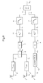
- a third embodiment of the invention represented in FIG. from the same receiving circuit as that described in Figure 5, it is intended to replace the third selection stage comprising the selection means provided out, by a third floor of combination and add to the second floor of processing of squaring means, 11 and 12 placed at the exit of amplifiers, respectively 7 and 8, preferentially in series with means of Low-pass filtering, respectively 13 and 14, to filter the high frequencies and recover the DC component of the signal.
- the third floor of combination comprises an adder 15 placed at the output of the filtering means to combine the received signals.
Landscapes
- Engineering & Computer Science (AREA)
- Computer Networks & Wireless Communication (AREA)
- Signal Processing (AREA)
- Variable-Direction Aerials And Aerial Arrays (AREA)
- Noise Elimination (AREA)
- Radio Transmission System (AREA)
Abstract
Description
Claims (5)
- Récepteur portable comprenant un premier étage de réception comportant trois antennes (1, 2 et 3) orientées de manière à former un repère sensiblement orthogonal, susceptible de recevoir un signal externe dans une plage de fréquence donnée, un deuxième étage de traitement des signaux délivrés (V1, V2 et V3) en sorties desdites antennes, et un troisième étage de sélection d'un des signaux délivrés en sortie dudit deuxième étage de traitement, caractérisé en ce que ledit deuxième étage de traitement comprend des premiers (4) et seconds (5) déphaseurs connectés en sortie de deux desdites antennes (1 et 2), lesdits signaux délivrés (V1 et V2) en sortie de ces deux antennes étant déphasés d'un angle de π/2 ou 3π/2 l'un par rapport à l'autre, et des moyens (6) pour combiner lesdits signaux déphasés (V4 et V5) formant un premier signal (S12) délivré audit troisième étage de sélection, en ce que ledit signal délivré (V3) par la troisième antenne correspond à un second signal délivré (S3) audit troisième étage de sélection, et en ce que ledit troisième étage de sélection comprend des moyens (9) pour sélectionner parmi lesdits deux signaux délivrés (S12 et S3) en sortie dudit deuxième étage, soit le signal ayant la plus grande amplitude, soit un des deux signaux ayant une amplitude supérieure à une amplitude de référence, soit arbitrairement un des deux signaux s'ils ont la même amplitude.
- Récepteur portable selon la revendication 1, caractérisé en ce que des moyens correcteurs (10) pour corriger l'atténuation introduite par les premier et second déphaseurs, sont placés entre ladite troisième antenne (3) et l'entrée correspondante (S3) desdits moyens de sélection (9).
- Récepteur portable selon la revendication 2, caractérisé en ce qu'un premier amplificateur (7) est placé entre les moyens (6) pour combiner les signaux déphasés (V4 et V5) et lesdits moyens de sélection (9) et en ce qu'un deuxième amplificateur (8) est placé entre les moyens correcteurs (10) et lesdits moyens de sélection (9).
- Récepteur portable comprenant un premier étage de réception comportant trois antennes (1, 2 et 3) orientées de manière à former un repère sensiblement orthogonal, susceptible de recevoir un signal externe dans une plage de fréquence donnée, un deuxième étage de traitement des signaux délivrés en sorties desdites antennes, et un troisième étage de combinaison des signaux délivrés en sortie dudit deuxième étage de traitement, caractérisé en ce que ledit deuxième étage de traitement comprend des premiers (4) et seconds (5) déphaseurs connectés en sortie de deux desdites antennes (1 et 2), lesdits signaux délivrés (V1 et V2) en sortie de ces deux antennes étant déphasés d'un angle de π/2 ou 3π/2 l'un par rapport à l'autre, et des moyens (6) pour combiner lesdits signaux déphasés (V4 et V5) formant un premier signal combiné (V12) fourni en entrée de premiers moyens élévateurs au carré (11), en ce que ledit deuxième étage de traitement comprend en outre des moyens correcteurs (10), placés à la sortie de la troisième antenne (3), pour corriger l'atténuation introduite par les premier et second déphaseurs en série avec des seconds moyens élévateurs au carré (12), et en ce que ledit troisième étage de combinaison comprend un additionneur (15) recevant en entrée les signaux (S4 et S5) fournis à la sortie desdits premiers et seconds moyens élévateurs au carré.
- Récepteur portable selon la revendication 4, caractérisé en ce que ledit deuxième étage de traitement comprend en outre des premiers (13) et deuxièmes (14) moyens de filtrage placés respectivement entre lesdits premiers (11) et deuxièmes (12) moyens élévateurs au carré et l'additionneur (15).
Priority Applications (3)
| Application Number | Priority Date | Filing Date | Title |
|---|---|---|---|
| EP02078252A EP1387502B1 (fr) | 2002-07-31 | 2002-07-31 | Récepteur portable à dispersion réduite |
| DE60207547T DE60207547T2 (de) | 2002-07-31 | 2002-07-31 | Tragbarer Empfänger mit verringerter Dispersion |
| US10/629,898 US20050288061A1 (en) | 2002-07-31 | 2003-07-30 | Portable receiver with reduced dispersion |
Applications Claiming Priority (1)
| Application Number | Priority Date | Filing Date | Title |
|---|---|---|---|
| EP02078252A EP1387502B1 (fr) | 2002-07-31 | 2002-07-31 | Récepteur portable à dispersion réduite |
Publications (2)
| Publication Number | Publication Date |
|---|---|
| EP1387502A1 true EP1387502A1 (fr) | 2004-02-04 |
| EP1387502B1 EP1387502B1 (fr) | 2005-11-23 |
Family
ID=30011220
Family Applications (1)
| Application Number | Title | Priority Date | Filing Date |
|---|---|---|---|
| EP02078252A Expired - Lifetime EP1387502B1 (fr) | 2002-07-31 | 2002-07-31 | Récepteur portable à dispersion réduite |
Country Status (3)
| Country | Link |
|---|---|
| US (1) | US20050288061A1 (fr) |
| EP (1) | EP1387502B1 (fr) |
| DE (1) | DE60207547T2 (fr) |
Cited By (1)
| Publication number | Priority date | Publication date | Assignee | Title |
|---|---|---|---|---|
| CN107710641A (zh) * | 2015-06-25 | 2018-02-16 | 艾尔斯潘网络公司 | 可配置天线以及操作此类可配置天线的方法 |
Families Citing this family (3)
| Publication number | Priority date | Publication date | Assignee | Title |
|---|---|---|---|---|
| US20080096509A1 (en) * | 2006-10-19 | 2008-04-24 | Maxlinear, Inc. | Low Complexity Diversity Receiver |
| GB0803348D0 (en) * | 2008-02-25 | 2008-04-02 | Rhodes Mark | Shallow water radio communications network |
| US9520052B2 (en) * | 2015-04-15 | 2016-12-13 | Innovative Control Systems, Inc. | Security tag system with improved range consistency |
Citations (4)
| Publication number | Priority date | Publication date | Assignee | Title |
|---|---|---|---|---|
| FR2763186A1 (fr) * | 1997-04-30 | 1998-11-13 | Siemens Ag | Recepteur de signaux portable |
| US5912925A (en) * | 1995-05-18 | 1999-06-15 | Aura Communications, Inc. | Diversity circuit for magnetic communication system |
| WO2000011753A1 (fr) * | 1998-08-22 | 2000-03-02 | Delphi Automotive Systems Deutschland Gmbh | Dispositif recepteur d'un systeme radio, et procede de traitement de signaux radio reçus |
| FR2792129A1 (fr) * | 1999-04-07 | 2000-10-13 | Valeo Securite Habitacle | Recepteur de signaux portable a plusieurs antennes |
Family Cites Families (6)
| Publication number | Priority date | Publication date | Assignee | Title |
|---|---|---|---|---|
| JP2561028B2 (ja) * | 1994-05-26 | 1996-12-04 | 日本電気株式会社 | サイドローブキャンセラ |
| US5553102A (en) * | 1994-12-01 | 1996-09-03 | Motorola, Inc. | Diversity reception communication system with maximum ratio combining method |
| US6895253B1 (en) * | 1995-03-14 | 2005-05-17 | Lucent Technologies Inc. | Wireless indoor communications using antenna arrays |
| JP3779063B2 (ja) * | 1998-05-28 | 2006-05-24 | 松下電器産業株式会社 | 無線通信装置及び無線通信方法 |
| US20040196805A1 (en) * | 2001-03-30 | 2004-10-07 | Xiaoyang Lee | Combined selective time switching transmission deversity (ststd) method and system |
| JP4252802B2 (ja) * | 2001-05-02 | 2009-04-08 | 富士通株式会社 | 送信ダイバーシチシステム |
-
2002
- 2002-07-31 DE DE60207547T patent/DE60207547T2/de not_active Expired - Lifetime
- 2002-07-31 EP EP02078252A patent/EP1387502B1/fr not_active Expired - Lifetime
-
2003
- 2003-07-30 US US10/629,898 patent/US20050288061A1/en not_active Abandoned
Patent Citations (4)
| Publication number | Priority date | Publication date | Assignee | Title |
|---|---|---|---|---|
| US5912925A (en) * | 1995-05-18 | 1999-06-15 | Aura Communications, Inc. | Diversity circuit for magnetic communication system |
| FR2763186A1 (fr) * | 1997-04-30 | 1998-11-13 | Siemens Ag | Recepteur de signaux portable |
| WO2000011753A1 (fr) * | 1998-08-22 | 2000-03-02 | Delphi Automotive Systems Deutschland Gmbh | Dispositif recepteur d'un systeme radio, et procede de traitement de signaux radio reçus |
| FR2792129A1 (fr) * | 1999-04-07 | 2000-10-13 | Valeo Securite Habitacle | Recepteur de signaux portable a plusieurs antennes |
Cited By (2)
| Publication number | Priority date | Publication date | Assignee | Title |
|---|---|---|---|---|
| CN107710641A (zh) * | 2015-06-25 | 2018-02-16 | 艾尔斯潘网络公司 | 可配置天线以及操作此类可配置天线的方法 |
| CN107710641B (zh) * | 2015-06-25 | 2021-07-06 | 艾尔斯潘网络公司 | 可配置天线以及操作此类可配置天线的方法 |
Also Published As
| Publication number | Publication date |
|---|---|
| US20050288061A1 (en) | 2005-12-29 |
| DE60207547T2 (de) | 2006-08-10 |
| EP1387502B1 (fr) | 2005-11-23 |
| DE60207547D1 (de) | 2005-12-29 |
Similar Documents
| Publication | Publication Date | Title |
|---|---|---|
| EP3528391B1 (fr) | Contrôleur nfc | |
| EP0415818B1 (fr) | Commande de pointage pour système d'antenne à balayage électronique et formation de faisceau par le calcul | |
| EP3715265B1 (fr) | Système et procédé d'estimation d'une erreur de pointage d'une antenne satellite | |
| EP2725712A1 (fr) | Système récepteur amélioré | |
| FR3004604A1 (fr) | Procede et appareil pour accorder automatiquement une matrice impedance, et emetteur radio utilisant cet appareil | |
| EP1429458A2 (fr) | Transformateur à changement de mode sélectif en fréquences | |
| EP1387502B1 (fr) | Récepteur portable à dispersion réduite | |
| EP2368134A1 (fr) | Circuit integrateur a multifenetrage temporel | |
| FR2792129A1 (fr) | Recepteur de signaux portable a plusieurs antennes | |
| EP1417750B1 (fr) | Circuit melangeur a rejection de frequence image, notamment pour un recepteur rf a frequence intermediaire nulle ou faible | |
| EP3176953B1 (fr) | Circuit d'impédance négative | |
| EP1178500A1 (fr) | Structure intégrée d'inductances à valeurs partagées sur un substrat semiconducteur | |
| EP1441437B1 (fr) | Générateur de signaux en quadrature de phase et à asservissement de la fréquence de travail | |
| EP0486094A1 (fr) | Dispositif de réception formé d'une pluralité de branches de réception | |
| EP1320199A1 (fr) | Récepteur portable à faible dispersion | |
| EP2642319A1 (fr) | Dispositif de réception de signaux de radio-navigation à antennes multiples et asservissement de synchronisation commun | |
| EP2457326B1 (fr) | Structure hyperfréquences de commutation à amplificateur distribué avec entrée d'injection de signal de test | |
| EP2656437A1 (fr) | Circuit formateur de faisceau et système d'antenne comprenant un tel circuit | |
| EP3516736B1 (fr) | Antenne à tiges ferromagnétiques bobinées et couplées entre elles | |
| EP1417777B1 (fr) | Recepteur portable a deux antennes | |
| FR3064135A1 (fr) | Dispositif de commutation hyperfrequence avec lecture par telemesure de l'etat des connections des entrees et sorties | |
| EP1324506A1 (fr) | Récepteur portable à deux antennes | |
| CA3037667C (fr) | Antenne a tiges ferromagnetiques bobinees et couplees entre elles | |
| EP1575161A1 (fr) | Circuit de conversion d'un signal différentiel en un signal non différentiel, et émetteur RF doté d'un tel circuit | |
| EP0511886A1 (fr) | Circuit déphaseur à modulation vectorielle |
Legal Events
| Date | Code | Title | Description |
|---|---|---|---|
| PUAI | Public reference made under article 153(3) epc to a published international application that has entered the european phase |
Free format text: ORIGINAL CODE: 0009012 |
|
| AK | Designated contracting states |
Kind code of ref document: A1 Designated state(s): AT BE BG CH CY CZ DE DK EE ES FI FR GB GR IE IT LI LU MC NL PT SE SK TR |
|
| AX | Request for extension of the european patent |
Extension state: AL LT LV MK RO SI |
|
| 17P | Request for examination filed |
Effective date: 20040804 |
|
| AKX | Designation fees paid |
Designated state(s): CH DE FR GB IT LI |
|
| GRAP | Despatch of communication of intention to grant a patent |
Free format text: ORIGINAL CODE: EPIDOSNIGR1 |
|
| GRAS | Grant fee paid |
Free format text: ORIGINAL CODE: EPIDOSNIGR3 |
|
| GRAA | (expected) grant |
Free format text: ORIGINAL CODE: 0009210 |
|
| AK | Designated contracting states |
Kind code of ref document: B1 Designated state(s): CH DE FR GB IT LI |
|
| REG | Reference to a national code |
Ref country code: GB Ref legal event code: FG4D Free format text: NOT ENGLISH |
|
| REG | Reference to a national code |
Ref country code: CH Ref legal event code: EP |
|
| REF | Corresponds to: |
Ref document number: 60207547 Country of ref document: DE Date of ref document: 20051229 Kind code of ref document: P |
|
| REG | Reference to a national code |
Ref country code: CH Ref legal event code: NV Representative=s name: ICB INGENIEURS CONSEILS EN BREVETS SA |
|
| GBT | Gb: translation of ep patent filed (gb section 77(6)(a)/1977) |
Effective date: 20060227 |
|
| PGFP | Annual fee paid to national office [announced via postgrant information from national office to epo] |
Ref country code: GB Payment date: 20060627 Year of fee payment: 5 |
|
| PLBE | No opposition filed within time limit |
Free format text: ORIGINAL CODE: 0009261 |
|
| STAA | Information on the status of an ep patent application or granted ep patent |
Free format text: STATUS: NO OPPOSITION FILED WITHIN TIME LIMIT |
|
| 26N | No opposition filed |
Effective date: 20060824 |
|
| GBPC | Gb: european patent ceased through non-payment of renewal fee |
Effective date: 20070731 |
|
| PG25 | Lapsed in a contracting state [announced via postgrant information from national office to epo] |
Ref country code: GB Free format text: LAPSE BECAUSE OF NON-PAYMENT OF DUE FEES Effective date: 20070731 |
|
| PGFP | Annual fee paid to national office [announced via postgrant information from national office to epo] |
Ref country code: IT Payment date: 20110618 Year of fee payment: 10 |
|
| PG25 | Lapsed in a contracting state [announced via postgrant information from national office to epo] |
Ref country code: IT Free format text: LAPSE BECAUSE OF NON-PAYMENT OF DUE FEES Effective date: 20120731 |
|
| REG | Reference to a national code |
Ref country code: FR Ref legal event code: PLFP Year of fee payment: 14 |
|
| REG | Reference to a national code |
Ref country code: FR Ref legal event code: PLFP Year of fee payment: 15 |
|
| REG | Reference to a national code |
Ref country code: FR Ref legal event code: PLFP Year of fee payment: 16 |
|
| REG | Reference to a national code |
Ref country code: FR Ref legal event code: PLFP Year of fee payment: 17 |
|
| PGFP | Annual fee paid to national office [announced via postgrant information from national office to epo] |
Ref country code: FR Payment date: 20210623 Year of fee payment: 20 |
|
| PGFP | Annual fee paid to national office [announced via postgrant information from national office to epo] |
Ref country code: CH Payment date: 20210622 Year of fee payment: 20 |
|
| PGFP | Annual fee paid to national office [announced via postgrant information from national office to epo] |
Ref country code: DE Payment date: 20210622 Year of fee payment: 20 |
|
| REG | Reference to a national code |
Ref country code: DE Ref legal event code: R071 Ref document number: 60207547 Country of ref document: DE |
|
| REG | Reference to a national code |
Ref country code: CH Ref legal event code: PL |