EP1387375A2 - Push button switch structure - Google Patents
Push button switch structure Download PDFInfo
- Publication number
- EP1387375A2 EP1387375A2 EP03017393A EP03017393A EP1387375A2 EP 1387375 A2 EP1387375 A2 EP 1387375A2 EP 03017393 A EP03017393 A EP 03017393A EP 03017393 A EP03017393 A EP 03017393A EP 1387375 A2 EP1387375 A2 EP 1387375A2
- Authority
- EP
- European Patent Office
- Prior art keywords
- reversing spring
- reversing
- push button
- button switch
- spring
- Prior art date
- Legal status (The legal status is an assumption and is not a legal conclusion. Google has not performed a legal analysis and makes no representation as to the accuracy of the status listed.)
- Withdrawn
Links
Images



Classifications
-
- H—ELECTRICITY
- H01—ELECTRIC ELEMENTS
- H01H—ELECTRIC SWITCHES; RELAYS; SELECTORS; EMERGENCY PROTECTIVE DEVICES
- H01H13/00—Switches having rectilinearly-movable operating part or parts adapted for pushing or pulling in one direction only, e.g. push-button switch
- H01H13/50—Switches having rectilinearly-movable operating part or parts adapted for pushing or pulling in one direction only, e.g. push-button switch having a single operating member
- H01H13/52—Switches having rectilinearly-movable operating part or parts adapted for pushing or pulling in one direction only, e.g. push-button switch having a single operating member the contact returning to its original state immediately upon removal of operating force, e.g. bell-push switch
-
- H—ELECTRICITY
- H01—ELECTRIC ELEMENTS
- H01H—ELECTRIC SWITCHES; RELAYS; SELECTORS; EMERGENCY PROTECTIVE DEVICES
- H01H13/00—Switches having rectilinearly-movable operating part or parts adapted for pushing or pulling in one direction only, e.g. push-button switch
- H01H13/70—Switches having rectilinearly-movable operating part or parts adapted for pushing or pulling in one direction only, e.g. push-button switch having a plurality of operating members associated with different sets of contacts, e.g. keyboard
- H01H13/7006—Switches having rectilinearly-movable operating part or parts adapted for pushing or pulling in one direction only, e.g. push-button switch having a plurality of operating members associated with different sets of contacts, e.g. keyboard comprising a separate movable contact element for each switch site, all other elements being integrated in layers
-
- H—ELECTRICITY
- H01—ELECTRIC ELEMENTS
- H01H—ELECTRIC SWITCHES; RELAYS; SELECTORS; EMERGENCY PROTECTIVE DEVICES
- H01H2215/00—Tactile feedback
- H01H2215/004—Collapsible dome or bubble
- H01H2215/006—Only mechanical function
-
- H—ELECTRICITY
- H01—ELECTRIC ELEMENTS
- H01H—ELECTRIC SWITCHES; RELAYS; SELECTORS; EMERGENCY PROTECTIVE DEVICES
- H01H2215/00—Tactile feedback
- H01H2215/034—Separate snap action
Definitions
- the present invention relates to a push button switch structure provided in a push button switch unit used for various kinds of electronic equipment, the push button switch structure including a reversing spring to form a movable contact.
- the former prior art comprises a fixed contact buried in a housing, a dome-shaped reversing spring, for example a reversing spring made of metal, which is arranged being opposed to the fixed contact in accessible manner, forming a movable contact and having a moderate rigidity and elasticity, and a stem having a press section abutting against a top of the reversing spring for giving a pressing force so as to reverse the reversing spring.
- a dome-shaped reversing spring for example a reversing spring made of metal
- the latter prior art comprises a fixed contact buried in a housing, a dome-shaped reversing spring, for example a reversing spring made of rubber material, which is arranged being opposed to the fixed contact in accessible manner, provided with a movable contact on a surface opposed to the fixed contact, and an operating section, i.e., a stem, having a press section abutting against the reversing spring for giving a pressing force so as to reverse the reversing spring.
- a dome-shaped reversing spring for example a reversing spring made of rubber material
- the stem when the stem is operated, the stem presses the reversing spring made of a rubber material. Accordingly, the reversing spring is reversed in such a manner as allowing a bottom thereof to bend. Then, the movable contact provided on the reversing spring becomes conductive with the fixed contact, whereby a predetermined signal can be outputted.
- the reversing spring made of rubber material is reversed, a loose, relatively dull click feel is obtained.
- the operational stroke until the movable contact of the reversing spring becomes conductive with the fixed contact may be set relatively long, along with a dimensional setting and the like as to the bottom of this reversing spring made of a rubber material.
- the present invention has been made considering the current situation of the prior arts as described above, and an objective of the present invention is to provide a press button switch structure that ensures both a relatively sharp click feel and relatively long operational stroke.
- the present invention forms a fixed contact and a movable contact accessible to the fixed contact, and comprises a first reversing spring being dome-shaped with rigidity and elasticity and a second reversing spring for conveying a pressing force to reverse the first reversing spring, the second reversing spring being made of a more flexible material than one of the first reversing spring, as well as being elastic, wherein, a gap dimension is set between the first reversing spring and the second reversing spring in order to reverse the first reversing spring and the second reversing spring nearly simultaneously.
- the aforementioned gap dimension which corresponds to a stroke until the second reversing spring made of a relatively flexible material abuts against the first reversing spring, can be included within the entire operational stroke.
- the operational stroke may be defined as a total of the aforementioned gap dimension and a stroke from a state where the second reversing spring abuts against the first reversing spring to a state where the first reversing spring is reversed. Then, it is possible to ensure a relatively long operational stroke.
- the first reversing spring having rigidity and elasticity, and the second reversing spring having a flexibility and elasticity can be reversed nearly simultaneously. Accordingly, it is possible to obtain a click feel combining the sharp click feel of the first reversing spring and the dull click feel of the second reversing spring. In other words, it is possible to ensure a relatively sharp click feel, comparing to the dull click feel of the second reversing spring.
- the present invention features that the first reversing spring is made of one of a synthetic resin having a conductive film on a surface opposed to the fixed contact and a metal, and the second reversing spring is made of one of a synthetic resin and a rubber material.
- the present invention features that the rubber material is in a dome shape.
- the present invention features that a bottom of the aforementioned second reversing spring abuts against a peripheral edge of the first reversing spring.
- the second reversing spring being flexible, to absorb fine vibration that occurs at the time of reversing the first reversing spring having rigidity.
- the present invention features that a spacer is provided between the bottom of the second reversing spring and the peripheral edge of the first reversing spring.
- the aforementioned gap dimension can be adjusted by the spacer.
- the present invention features that a dustproof sheet for covering the first reversing spring is provided.
- the present invention features that it is provided in a push button switch unit as a discrete piece accommodated in an independent outer shell.
- the present invention features that it is provided in each of a plurality of push button switch units formed via a sheet-like member.
- Fig. 1 is a longitudinal sectional view showing the first embodiment of the present invention, which is applied to a push button switch unit as a discrete piece accommodated in an independent outer shell.
- the first embodiment comprises a housing 1 forming the outer shell, fixed contacts 2, 3 buried in the bottom of the housing 1, and an external connecting terminal, not illustrated, one end of which is connected to the above fixed contacts and the other end of which is derived out of the housing.
- the first embodiment further comprises a first reversing spring 4, which is arranged in a manner opposed to the fixed contacts 2, 3 and a peripheral edge of the first reversing spring keeps contact with the fixed contact 2, as well as forming a movable contact that is selectively accessible to the fixed contact 3.
- This first reversing spring 4 is dome-shaped having a moderate rigidity and elasticity.
- the dome shape is formed by a process of drawing using a metallic material.
- a second reversing spring 5 is provided, which is also elastic but made of a more flexible material comparing to that of the first reversing spring 4.
- This second reversing spring 5 comprises a rubber material for example dome-shaped, a bottom 6 thereof abutting against the peripheral edge of the first reversing spring 4, and a press section 7 for conveying a pressing force to reverse the first reversing spring 4.
- a gap dimension 8 is set in advance, for reversing the first reversing spring 4 and the second reversing spring 5 nearly simultaneously.
- a stem 9 that is capable of performing a pressing operation against the second reversing spring 5 is provided.
- the second reversing spring 5 made of a rubber material is dented and comes down, the peripheral side section 10 thereof starts bending, and then, the press section 7 abuts against the top of the first reversing spring 4 made of metal. Subsequent pressing force put on the stem 9 allows that the second reversing spring 5 is reversed, and nearly simultaneously the first reversing spring 4 is reversed by a force given via the press section 7 of the second reversing spring 5. When the first reversing spring 4 is reversed, the first reversing spring 4 becomes conductive with the fixed contact 3, and then a predetermined signal is outputted.
- the gap dimension 8 in the entire operational stroke, the gap dimension 8 corresponding to a stroke until the press section 7 of the second reversing spring 5 comes into abutment against the top of the first reversing spring 4.
- the operational stroke can be defined as a total of the above gap dimension 8 and a stroke from a state where the press section 7 of the second reversing spring 5 abuts against the first reversing spring 4 until a state where the first reversing spring 4 is reversed and becomes conductive with the fixed contact 3. Therefore, it is possible to ensure a relatively long operational stroke.
- Fig. 2 is an illustration showing an operating force and a stroke characteristic of the first reversing spring 4 made of metal provided in the first embodiment.
- a stroke forming a reversed area t1 is relatively short. With this short stroke, it is possible to secure a sharp click feel.
- the stroke S1 from a time when the operating force is given to a time when the reversing operation is completed is also relatively short.
- Fig. 3 is an illustration showing an operating force and a stroke characteristic of the second reversing spring 5 made of rubber material, provided in the first embodiment.
- a stroke forming a reversed area t2 is relatively long. With this long stroke, the click feel becomes soft and dull.
- the stroke S2 from a time when the operating force is given to a time when the reversing operation is completed is also relatively long.
- Fig. 4 is an illustration showing an operating force and a stroke characteristic of the first embodiment.
- a stroke forming a reversed area t3 can be made shorter than the stroke characteristic of the second reversing spring 5 as shown in Fig. 3. Accordingly, it is possible to ensure a sharper click feel comparing to the click feel of the second reversing spring 5 only. Furthermore, it is possible to secure a stroke S3 from a time when the operating force is given to when a time the reversing operation is completed, which is longer than the stroke characteristic of the first reversing spring 4.
- a bottom 6 of the second reversing spring 5 made of a rubber material abuts against the peripheral edge of the first reversing spring 4 made of metal. Therefore, a fine vibration, which is generated on the first reversing spring 4 at the time of reversing the first reversing spring 4, can be absorbed by the flexible second reversing spring 5, thereby preventing uncomfortable vibration noise from occurring.
- Fig. 5 is a perspective view showing the second embodiment of the present invention applied to each of a plurality of push button switch units formed via a sheet-like member.
- Fig. 6 is a longitudinal sectional view showing a substantial part of the second embodiment as shown in Fig. 5.
- a plurality of first reversing springs 12 made of metal are provided on a print circuit board 11.
- a rubber sheet 14 is provided, which is integrally formed with a plurality of second reversing springs 13.
- the second reversing springs 13 are arranged respectively to locate on the corresponding first reversing springs 12.
- each of the first reversing springs 12 there are formed a first contact pattern 15 against which the peripheral edge of the first reversing spring 12 abuts constantly, and a fixed contact pattern 16 with which the first reversing spring 12 can be conductive in accordance with the reversing operation of the first reversing spring 12.
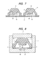
- Fig. 7 is a substantial part of the third embodiment of the present invention.
- the third embodiment as shown in Fig. 7 is an invention applied to a sheet-like member provided with a plurality of push button switch units on the print circuit board 11.
- a switch unit 19 being single item, is arranged.
- the first reversing spring 12 made of metal, equivalent to that of aforementioned second embodiment is disposed, which is not shown in the illustration.
- the switch unit 19 is provided with a stem 20 that is capable of pressing the first reversing spring 12.
- a gap dimension 21 for nearly simultaneously reversing the first reversing spring 12 within the switch unit 19 and the second reversing spring 13 is set between the press section 17 of the second reversing spring 13 and the stem 20.
- the second reversing spring 13 by pressing each of the second reversing springs 13, then it is bent, and the second reversing spring 13 comes into abutment against the stem 20 of the switch unit 19. Subsequent pressing of the second reversing spring 13 allows it to reverse.
- the first reversing spring 12, not illustrated, within the switch unit 19 is pressed by the stem 20, and the first reversing spring 12 is reversed nearly simultaneously with reversing of the second reversing spring 13. Accordingly, the first reversing spring 12 is conductive to the fixed contact pattern, not illustrated, on the print circuit board 11, so that a predetermined signal is outputted.
- the third embodiment as configured above can obtain an operational advantage equivalent to those of the first and the second embodiments as described above, in accordance with providing the aforementioned gap dimension 21.
- Fig. 8 is a longitudinal sectional view showing the fourth embodiment of the present invention, which is applied to a push button switch unit as a discrete piece accommodated in an independent outer shell.
- the top of the first reversing spring 4 is pressed by the press section 7 of the second reversing spring 5, and at the time of reversing, the first reversing spring 4 comes into abutment against both the fixed contacts 30 and 31. Accordingly, the fixed contacts 30 and 31 become conductive therebetween and a predetermined signal is outputted.
- the fourth embodiment as configured above can obtain an operational advantage equivalent to that of the first embodiment as described above, in accordance with providing the gap dimension 8.
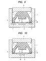
- Fig. 9 is also a longitudinal sectional view showing the fifth embodiment of the present invention, which is applied to a push button switch unit as a discrete piece accommodated in an independent outer shell.
- a spacer 22 for example ring-shaped, is provided between the peripheral edge of the first reversing spring 4 and the bottom 6 of the second reversing spring 5.
- Other structures are equivalent to those of the first embodiment.
- the fifth embodiment as configured above can obtain an operational advantage equivalent to that of the first embodiment as described above, in accordance with providing the gap dimension 8.
- the gap dimension 8 formed between the first reversing spring 4 and the press section 7 of the second reversing spring 5 can be adjusted.
- this time deviation can be corrected easily by appropriately selecting the height dimension of the spacer 22. Accordingly, it is possible to achieve a reversing operation with a high degree of precision, including both the reverse of the first reversing spring 4 and that of the second reversing spring 5, and switching performance is enhanced.
- Fig. 10 is also a longitudinal sectional view showing the sixth embodiment of the present invention, which is applied to a push button switch unit as a discrete piece accommodated in an independent outer shell.
- the sixth embodiment is configured as being provided with the fixed contacts 30 and 31 arrangement, equivalent to those of the aforementioned fourth embodiment as shown in Fig. 8, as well as a spacer 22 equivalent to that of the aforementioned fifth embodiment as shown in Fig. 9.
- Fig. 11 is a longitudinal sectional view showing the seventh embodiment of the present invention, which is applied to a push button switch unit as a discrete piece accommodated in an independent outer shell.
- a flexible dustproof sheet 23 is provided in such a manner as covering the first reversing spring 4.
- This dustproof sheet 23 is disposed, for example, in such a manner as being held tight between the spacer 22 and the bottom 6 of the second reversing spring 5.
- Other structures are equivalent to those of the aforementioned fifth embodiment as shown in Fig. 9.
- the dustproof sheet 23 thus provided for covering the first reversing spring 4, it is possible to prevent dust from entering a contact formed by the first reversing spring 4 and the fixed contacts 2 and 3, the dust entering between the bottom 6 of the second reversing spring 5 and the internal wall surface of the housing 1 in accordance with a reversing operation of the flexible second reversing spring 5. Accordingly, it is possible to prevent a poor connection at the contact due to the dust, and then durability is enhanced.
- Fig. 12 is also a longitudinal sectional view showing the eighth embodiment of the present invention, which is applied to a push button switch unit as a discrete piece accommodated in an independent outer shell.
- the eighth embodiment is configured as being provided with arrangements of the fixed contacts 30, 31 and the spacer 22, equivalent to that of the aforementioned embodiment as shown in Fig. 10, as well as provided with the dustproof sheet 23 for covering the first reversing spring 4, which is equivalent to that of the aforementioned seventh embodiment as shown in Fig. 11.
- the spacer 22 is disposed at the bottom of the housing 1, and the dustproof sheet 23 is disposed in such a manner as being held tight between the spacer 22 and the bottom of the housing 1.
- Other structures are equivalent to those of the aforementioned first embodiment as shown in Fig. 1.
- metal is used to configure the first reversing spring 4 or 12.
- metal instead of configuring with the metal, it is also possible to use a synthetic resin, having a moderate rigidity and elasticity, and formed with a conductive film such as carbon coating on a surface opposed to the fixed contact.
- a rubber material is used to configure the second reversing spring 5 or 13.
- a synthetic resin having a moderate flexibility and elasticity.
- the present invention is configured such that between the first reversing spring having rigidity and elasticity and the second reversing spring made of a more flexible material than one of the first reversing spring and having elasticity, a gap dimension is set for reversing the first reversing spring and the second reversing spring nearly simultaneously.
- the present invention is configured such that the bottom of the second reversing spring abuts against the peripheral edge of the first reversing spring.
- the present invention is configured such that a spacer is disposed between the bottom of the second reversing spring and the peripheral edge of the first reversing spring.
- the present invention is configured such that a dustproof sheet covering the first reversing spring is provided.
- a dustproof sheet covering the first reversing spring is provided.
Landscapes
- Push-Button Switches (AREA)
Abstract
Description
Claims (8)
- A push button switch structure forming therein a fixed contact and a movable contact accessible to the fixed contact and comprising,a first reversing spring being dome-shaped with rigidity and elasticity, anda second reversing spring for conveying a pressing force to reverse the first reversing spring, the second reversing spring being made of a more flexible material than one of the first reversing spring, as well as being elastic, whereina gap dimension is set between the first reversing spring and the second reversing spring in order to reverse the first reversing spring and the second reversing spring nearly simultaneously.
- A push button switch structure according to claim 1, wherein
the first reversing spring is made of one of a synthetic resin with a conductive film on a surface opposed to the fixed contact and a metal, and
wherein the second reversing spring is made of one of a synthetic resin and a rubber material. - A push button switch structure according to claim 2, wherein the rubber material is formed in a dome shape.
- A push button switch structure according to any of claims 1 to 3, wherein a bottom of the second reversing spring abuts against a peripheral edge of the first reversing spring.
- A push button switch structure according to any of claims 1 to 4, wherein a spacer is provided between the bottom of the second reversing spring and the peripheral edge of the first reversing spring.
- A push button switch structure according to any of claims 1 to 5, wherein a dustproof sheet for covering the first reversing spring is provided.
- A push button switch structure according to any of claims 1 to 6, which is provided in a push button switch unit as a discrete piece accommodated in an independent outer shell.
- A push button switch structure according to any of claims 1 to 7, which is provided in each of a plurality of push button switch units formed via a sheet-like member.
Applications Claiming Priority (2)
| Application Number | Priority Date | Filing Date | Title |
|---|---|---|---|
| JP2002226107A JP2004071225A (en) | 2002-08-02 | 2002-08-02 | Push-button switch structure |
| JP2002226107 | 2002-08-02 |
Publications (2)
| Publication Number | Publication Date |
|---|---|
| EP1387375A2 true EP1387375A2 (en) | 2004-02-04 |
| EP1387375A3 EP1387375A3 (en) | 2005-04-20 |
Family
ID=30112994
Family Applications (1)
| Application Number | Title | Priority Date | Filing Date |
|---|---|---|---|
| EP03017393A Withdrawn EP1387375A3 (en) | 2002-08-02 | 2003-07-31 | Push button switch structure |
Country Status (5)
| Country | Link |
|---|---|
| EP (1) | EP1387375A3 (en) |
| JP (1) | JP2004071225A (en) |
| KR (1) | KR100675545B1 (en) |
| CN (1) | CN1233000C (en) |
| TW (1) | TWI228736B (en) |
Cited By (5)
| Publication number | Priority date | Publication date | Assignee | Title |
|---|---|---|---|---|
| DE102007045871A1 (en) * | 2007-09-25 | 2009-04-23 | Albrecht Jung Gmbh & Co. Kg | Electrical / electronic installation device |
| WO2017045167A1 (en) * | 2015-09-16 | 2017-03-23 | 尚平 | Control apparatus for switch and electronic whistle |
| US10337758B2 (en) | 2014-09-25 | 2019-07-02 | Panasonic Intellectual Property Management Co., Ltd. | Heat exchanger ventilator |
| DE102018108660B3 (en) * | 2018-04-12 | 2019-10-17 | Preh Gmbh | Switch arrangement with switching mat for operating a motor vehicle component |
| EP3806121A4 (en) * | 2018-05-24 | 2021-08-11 | Panasonic Intellectual Property Management Co., Ltd. | PUSH BUTTON SWITCH |
Families Citing this family (6)
| Publication number | Priority date | Publication date | Assignee | Title |
|---|---|---|---|---|
| JP2006107821A (en) * | 2004-10-01 | 2006-04-20 | Calsonic Kansei Corp | Operating switch |
| WO2007065253A1 (en) * | 2005-12-05 | 2007-06-14 | Omron Dualtec Automotive Electronics Inc. | Electrical switch |
| JP2010251100A (en) * | 2009-04-15 | 2010-11-04 | Alps Electric Co Ltd | Input device |
| JP5590745B2 (en) * | 2012-08-22 | 2014-09-17 | 不二電子工業株式会社 | Long stroke dome type movable contact |
| JP6322814B2 (en) * | 2014-09-25 | 2018-05-16 | パナソニックIpマネジメント株式会社 | Heat exchange ventilator |
| CN204927141U (en) * | 2015-09-06 | 2015-12-30 | 东莞市凯华电子有限公司 | A thin keyboard switch |
Family Cites Families (3)
| Publication number | Priority date | Publication date | Assignee | Title |
|---|---|---|---|---|
| FR2659459B1 (en) * | 1990-03-08 | 1993-11-26 | Sextant Avionique | TOUCH EFFECT KEY AND KEYBOARD USING THE SAME. |
| GB2321134A (en) * | 1996-12-24 | 1998-07-15 | Nokia Mobile Phones Ltd | An assembly for a keypad |
| CN1145993C (en) * | 1998-12-22 | 2004-04-14 | 三菱电机株式会社 | Switches, locking plates for switches and fixing methods for locking plates for switches |
-
2002
- 2002-08-02 JP JP2002226107A patent/JP2004071225A/en not_active Withdrawn
-
2003
- 2003-07-22 KR KR1020030050288A patent/KR100675545B1/en not_active Expired - Fee Related
- 2003-07-31 TW TW092120997A patent/TWI228736B/en not_active IP Right Cessation
- 2003-07-31 EP EP03017393A patent/EP1387375A3/en not_active Withdrawn
- 2003-08-04 CN CNB031526462A patent/CN1233000C/en not_active Expired - Fee Related
Cited By (8)
| Publication number | Priority date | Publication date | Assignee | Title |
|---|---|---|---|---|
| DE102007045871A1 (en) * | 2007-09-25 | 2009-04-23 | Albrecht Jung Gmbh & Co. Kg | Electrical / electronic installation device |
| DE102007045871B4 (en) * | 2007-09-25 | 2009-10-29 | Albrecht Jung Gmbh & Co. Kg | keypad |
| US10337758B2 (en) | 2014-09-25 | 2019-07-02 | Panasonic Intellectual Property Management Co., Ltd. | Heat exchanger ventilator |
| WO2017045167A1 (en) * | 2015-09-16 | 2017-03-23 | 尚平 | Control apparatus for switch and electronic whistle |
| DE102018108660B3 (en) * | 2018-04-12 | 2019-10-17 | Preh Gmbh | Switch arrangement with switching mat for operating a motor vehicle component |
| US10727011B2 (en) | 2018-04-12 | 2020-07-28 | Preh Gmbh | Switch assembly for operating a motor vehicle component |
| EP3806121A4 (en) * | 2018-05-24 | 2021-08-11 | Panasonic Intellectual Property Management Co., Ltd. | PUSH BUTTON SWITCH |
| US11355294B2 (en) | 2018-05-24 | 2022-06-07 | Panasonic Intellectual Property Management Co., Ltd. | Push switch |
Also Published As
| Publication number | Publication date |
|---|---|
| CN1233000C (en) | 2005-12-21 |
| KR100675545B1 (en) | 2007-01-29 |
| KR20040012486A (en) | 2004-02-11 |
| TWI228736B (en) | 2005-03-01 |
| JP2004071225A (en) | 2004-03-04 |
| EP1387375A3 (en) | 2005-04-20 |
| CN1480969A (en) | 2004-03-10 |
| TW200418062A (en) | 2004-09-16 |
Similar Documents
| Publication | Publication Date | Title |
|---|---|---|
| US7442886B2 (en) | Multi-directional input unit | |
| US20080296141A1 (en) | Key Input Apparatus and Electronic Device | |
| US7285741B2 (en) | Push-button switch | |
| US20180151313A1 (en) | Push switch | |
| CN215451206U (en) | Movable member and input device | |
| EP1950782B1 (en) | Elastic member for pushbutton switch | |
| KR100675545B1 (en) | Push button switch structure | |
| US8188388B2 (en) | Operation key structure | |
| EP1049122B1 (en) | Oscillating-operation type switch apparatus | |
| CN112189246B (en) | Push switch | |
| JP2000149701A (en) | Push button device and mobile phone radio | |
| US5929401A (en) | Curved keyboard keypad and contact structure | |
| US7560655B2 (en) | Movable contact and push switch using the same | |
| JP2673288B2 (en) | Key switch rubber spring | |
| JP2002216582A (en) | Movable contact body | |
| US7238896B2 (en) | Switch device | |
| JP2008311101A (en) | Key switch structure | |
| JPS6345706Y2 (en) | ||
| JP2008181897A (en) | Push-button switch | |
| JP2557784Y2 (en) | Tact switch | |
| KR100508121B1 (en) | A Key Input Device For Mobile Phone | |
| JPH0343627Y2 (en) | ||
| JPH0193015A (en) | Rubber switch with keytop | |
| JP5445436B2 (en) | Switch-integrated casing and electronic device having the same | |
| JP4090275B2 (en) | Key top mounting structure |
Legal Events
| Date | Code | Title | Description |
|---|---|---|---|
| PUAI | Public reference made under article 153(3) epc to a published international application that has entered the european phase |
Free format text: ORIGINAL CODE: 0009012 |
|
| AK | Designated contracting states |
Kind code of ref document: A2 Designated state(s): AT BE BG CH CY CZ DE DK EE ES FI FR GB GR HU IE IT LI LU MC NL PT RO SE SI SK TR |
|
| AX | Request for extension of the european patent |
Extension state: AL LT LV MK |
|
| PUAL | Search report despatched |
Free format text: ORIGINAL CODE: 0009013 |
|
| AK | Designated contracting states |
Kind code of ref document: A3 Designated state(s): AT BE BG CH CY CZ DE DK EE ES FI FR GB GR HU IE IT LI LU MC NL PT RO SE SI SK TR |
|
| AX | Request for extension of the european patent |
Extension state: AL LT LV MK |
|
| 17P | Request for examination filed |
Effective date: 20050517 |
|
| AKX | Designation fees paid |
Designated state(s): DE FR GB IT |
|
| STAA | Information on the status of an ep patent application or granted ep patent |
Free format text: STATUS: THE APPLICATION HAS BEEN WITHDRAWN |
|
| 18W | Application withdrawn |
Effective date: 20090820 |