EP1387134B1 - Drier for refrigerant condenser - Google Patents
Drier for refrigerant condenser Download PDFInfo
- Publication number
- EP1387134B1 EP1387134B1 EP03015294A EP03015294A EP1387134B1 EP 1387134 B1 EP1387134 B1 EP 1387134B1 EP 03015294 A EP03015294 A EP 03015294A EP 03015294 A EP03015294 A EP 03015294A EP 1387134 B1 EP1387134 B1 EP 1387134B1
- Authority
- EP
- European Patent Office
- Prior art keywords
- collector
- refrigerant
- drier
- dryer
- molded part
- Prior art date
- Legal status (The legal status is an assumption and is not a legal conclusion. Google has not performed a legal analysis and makes no representation as to the accuracy of the status listed.)
- Expired - Lifetime
Links
- 239000003507 refrigerant Substances 0.000 title claims description 42
- 238000002347 injection Methods 0.000 claims abstract description 23
- 239000007924 injection Substances 0.000 claims abstract description 23
- 239000002808 molecular sieve Substances 0.000 claims abstract description 18
- URGAHOPLAPQHLN-UHFFFAOYSA-N sodium aluminosilicate Chemical compound [Na+].[Al+3].[O-][Si]([O-])=O.[O-][Si]([O-])=O URGAHOPLAPQHLN-UHFFFAOYSA-N 0.000 claims abstract description 18
- 229920000642 polymer Polymers 0.000 claims abstract description 15
- 238000001035 drying Methods 0.000 claims abstract description 8
- 238000004378 air conditioning Methods 0.000 claims abstract description 7
- 239000011159 matrix material Substances 0.000 claims 3
- 239000000463 material Substances 0.000 abstract description 5
- 239000002861 polymer material Substances 0.000 abstract description 3
- 239000002826 coolant Substances 0.000 abstract 4
- 230000015572 biosynthetic process Effects 0.000 abstract 1
- 239000003990 capacitor Substances 0.000 description 8
- 239000008187 granular material Substances 0.000 description 7
- 238000004519 manufacturing process Methods 0.000 description 5
- 238000005516 engineering process Methods 0.000 description 4
- 239000000203 mixture Substances 0.000 description 4
- 239000000047 product Substances 0.000 description 3
- 238000001816 cooling Methods 0.000 description 2
- 238000001746 injection moulding Methods 0.000 description 2
- 239000002245 particle Substances 0.000 description 2
- 238000007789 sealing Methods 0.000 description 2
- 239000007787 solid Substances 0.000 description 2
- 125000006850 spacer group Chemical group 0.000 description 2
- XLYOFNOQVPJJNP-UHFFFAOYSA-N water Substances O XLYOFNOQVPJJNP-UHFFFAOYSA-N 0.000 description 2
- 238000005299 abrasion Methods 0.000 description 1
- 239000000853 adhesive Substances 0.000 description 1
- 230000001070 adhesive effect Effects 0.000 description 1
- 239000013065 commercial product Substances 0.000 description 1
- 230000018044 dehydration Effects 0.000 description 1
- 238000006297 dehydration reaction Methods 0.000 description 1
- 239000004744 fabric Substances 0.000 description 1
- 238000005429 filling process Methods 0.000 description 1
- 238000001914 filtration Methods 0.000 description 1
- 239000007791 liquid phase Substances 0.000 description 1
- 238000012423 maintenance Methods 0.000 description 1
- 230000000284 resting effect Effects 0.000 description 1
- 239000000243 solution Substances 0.000 description 1
- 239000000126 substance Substances 0.000 description 1
- 239000012808 vapor phase Substances 0.000 description 1
Images
Classifications
-
- F—MECHANICAL ENGINEERING; LIGHTING; HEATING; WEAPONS; BLASTING
- F25—REFRIGERATION OR COOLING; COMBINED HEATING AND REFRIGERATION SYSTEMS; HEAT PUMP SYSTEMS; MANUFACTURE OR STORAGE OF ICE; LIQUEFACTION SOLIDIFICATION OF GASES
- F25B—REFRIGERATION MACHINES, PLANTS OR SYSTEMS; COMBINED HEATING AND REFRIGERATION SYSTEMS; HEAT PUMP SYSTEMS
- F25B39/00—Evaporators; Condensers
- F25B39/04—Condensers
-
- F—MECHANICAL ENGINEERING; LIGHTING; HEATING; WEAPONS; BLASTING
- F25—REFRIGERATION OR COOLING; COMBINED HEATING AND REFRIGERATION SYSTEMS; HEAT PUMP SYSTEMS; MANUFACTURE OR STORAGE OF ICE; LIQUEFACTION SOLIDIFICATION OF GASES
- F25B—REFRIGERATION MACHINES, PLANTS OR SYSTEMS; COMBINED HEATING AND REFRIGERATION SYSTEMS; HEAT PUMP SYSTEMS
- F25B2339/00—Details of evaporators; Details of condensers
- F25B2339/04—Details of condensers
- F25B2339/044—Condensers with an integrated receiver
- F25B2339/0441—Condensers with an integrated receiver containing a drier or a filter
Definitions
- the invention relates to a dryer for a refrigerant circuit, in particular for motor vehicle air conditioners, and a collector with such a dryer and a heat exchanger with such a collector.
- a dryer was by the DE-A 197 12 714 the applicant known.
- the invention also relates to the use of a polymer product known under the trademark CSP Technologies .
- Automotive air conditioning systems are operated with a refrigerant (R134 a), which, for. B. due to leaks in the system after a period of operation moisture (H2O) absorbs.
- This water in the refrigerant is undesirable and is therefore removed by means of a dryer located either in a separate collector or a collector integrated with the condenser.
- the applicant has known a so-called capacitor module in which the collector is integrated into the capacitor and accommodates a dryer cartridge or a so-called dryer bag.
- the dryer cartridge consists of a perforated plastic container, which is filled with dryer granules, z. B. off Molecular sieve is filled.
- the dryer bag consists of a permeable to the refrigerant fabric or nonwoven and is also filled with dryer granules.
- a similar dryer cartridge was replaced by the DE-A 197 12 714 the applicant: it consists of a cage-like plastic container, which is lined with a sieve and also receives dryer granules in the form of a bed in itself. So that the granules are not subjected to excessive abrasion during operation in the vehicle, the granule filling is compressed by a spring-loaded disc which is movable within the plastic container.
- These known dryer designs for refrigerant circuits are associated with a certain manufacturing and cost in terms of their production and shipment and positioning in the collector.
- US-A-4 013566 discloses a dryer which is formed as a hollow cylindrical injection molded part and contains a polymer and molecular sieve.
- the dryer is produced as a plastic injection-molded part from a known mass, which consists essentially of a polymer, a so-called channel former and a molecular sieve.
- the molecular sieve performs the function of drying, ie the dehydration of the refrigerant.
- the channel former causes channels to form in the polymer composition.
- the refrigerant has access from the outside to the molecular sieve and can be dried.
- the advantage of this dryer is that two functions, namely the container and the drying are combined in an injection molded part, because the polymer material absorbs the dryer in itself and thus acts as a sort of container.
- the entire dryer is made of plastic, such as the commercially available material sold under the trademark "CSP Technologies", as an injection molded part of any shape.
- the injection molded part is adapted to the inner shape of a collector of the refrigerant circuit.
- the injection-molded part can be solid or else designed as a hollow body - it merely has to provide sufficient drying material (molecular sieve) for the drying of the refrigerant.
- This injection molded part can also be arranged at any point in the collector and z. B. be fixed by clamping.
- the outer surface of the injection molded part is provided with openings, through which the refrigerant receives better access to the "channel system" with the embedded molecular sieve.
- an enlargement of the surface of the injection-molded part which is achieved for example by elevations and / or depressions such as depressions, grooves, grooves and the like.
- the injection molded part may for example have a fir tree-shaped structure.
- the solution to the above problem is also the use of a known polymer product, which is known and sold under the brand CSP Technologies .
- the new use of this product is that it is processed as an injection molded part in a plastic injection molding machine and used as a dryer for dehydrating refrigerant of an air conditioner.
- the polymer composition is thus used as an amorphous carrier of the molecular sieve or dryer material.
- the dryer according to the invention can be connected to a filter unit, so that a refrigerant flowing through or flowing around the dryer is also filtered.
- the connection is here For example, a plug, a Clips-, an adhesive or any other connection.
- the dryer forms a structural unit with a filter unit.
- the filter unit may, for example, have a fine-meshed network, are filtered with the foreign body as with a sieve from the refrigerant.
- the dryer according to the invention is used in a collector for a refrigerant in a closed circuit, so that a refrigerant flowing through the collector can be dried, that is, that the refrigerant water can be withdrawn.
- a filter element arranged in the direction of flow before or after the dryer such as a sieve, the refrigerant can optionally be additionally filtered, with which the collector combines several functions in itself.
- the collector is used with the dryer according to the invention in a heat exchanger with tubes, fins and two headers such that a refrigerant which flows through the heat exchanger, before, during or subsequently flows through the collector.
- the heat exchanger is designed as a capacitor.
- Such heat exchangers are through the DE 42 38 853 C2 known.
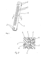
- Fig. 1 shows an injection molded part 1, which acts as a dryer in the refrigerant circuit of a motor vehicle air conditioning, not shown.
- This injection-molded part 1 is produced by injection molding as a solid cylinder made of a special plastic mixture, which will be explained below.
- the injection molded part 1 has circumferentially distributed cam-like spacers 2, which serve to fix in a housing, not shown here.
- openings 3 are provided, which allow a better access of the refrigerant into the internal structure of the dryer 1.
- the mass of this injection-molded part 1 is porous, wherein the carrier, which also causes the strength, consists of a polymer.
- the plastic in the form of polymer is traversed by a multiplicity of channels, which are produced by a so-called channel former during manufacture. In these channels is incorporated as a third component, a molecular sieve in the form of particles.
- Such a plastic blend is known as a commercial product under the CSP Technologies brand.
- FIG. 2 shows an enlarged view of a detail X from a section in the plane II-II through the mass of the injection molded part 1 - in a highly simplified, schematic representation.
- a carrier substance 4 cross-hatched
- channels 5 are about cubic particles 6 (hatched) embedded, which are referred to as molecular sieve and consist of a known dryer material. This molecular sieve 6 is therefore able to absorb the moisture contained in the refrigerant.
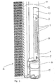
- Fig. 3 shows a portion of a refrigerant condenser 10 having a manifold 11 and an integrated collector 12, the z. T. shown as a view and z. T. is cut open, ie the window 13 releases the view into the interior.
- the collector 12 is connected in a known manner via the two overflow openings 14, 15 with the manifold 11, so that the collector 13 is constantly flowed through during operation of the air conditioner of refrigerant.
- the overflow opening 14 of the dryer 1 shown in Fig. 1 is arranged, approximately coaxial with the cross section of the collector 13.
- an annular gap 16 over the the refrigerant (not shown) rise in the liquid or vapor phase and the surface of the dryer 1 wash around or can flow around.
- the refrigerant first penetrates under the surface of the injection molded part 1 and thus enters the channel structure 5 shown schematically in FIG. 2 with the molecular sieve 6. This causes a drying of the refrigerant.
- the collector 13 can - which is not shown here - be provided with a removable lid, so that an exchange of the injection molded part 1 for maintenance is possible.
- the injection molded part 1 is fixed in a manner not shown in the collector 13, z. B. by clamping with the inner wall of the collector 13 or by resting on a screen member, not shown, in the lower region of the collector thirteenth
- this dryer In the illustrated position of the dryer 1, the latter is therefore not flowed through by the refrigerant, as is the case in the prior art with granulate containers, but substantially flows around it, the refrigerant diffusing from the outside through the openings 3 into the channel system of the porous mass , In this respect, this dryer also does not represent a flow resistance for the refrigerant.
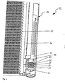
- FIG. 4 shows a further arrangement of a dryer 20 in a collector 21 of a capacitor module 22.
- the dryer 20 consists of a polymer, a channel former and a molecular sieve, and in contrast to the dryer illustrated in FIG. 3, is formed integrally with a filter unit 23 in that the filter unit 23 is injection-molded onto the dryer 20.
- the filter unit 23 has a frame 24 with openings 25 for a flow of a refrigerant.
- Sealing lips 26 provide a seal against the collector 21, so that the refrigerant is forced to flow through a screen 27 injected into the filter unit 23.
- the sealing lips 26 serve to fix the component group consisting of the filter unit 23 and the dryer 20 in the collector 21.
- the collector 21 is integrated into the capacitor module 22 in such a way that a refrigerant flowing through the condenser 22, after cooling in the tube-and-fin network 28, flows through an inlet opening 29 from a collector tube 30 of the capacitor module 22 into the collector 21. After an optional drying in the dryer 20 and a filtering by the filter unit 23, the refrigerant flows through an outlet opening 31 back into the manifold 30 and from there to a further cooling in a not further identified subcooling of the capacitor module 22nd
Abstract
Description
Die Erfindung betrifft einen Trockner für einen Kältemittelkreislauf, insbesondere für Kraftfahrzeugklimaanlagen, sowie einen Sammler mit einem solchen Trockner und einen Wärmetauscher mit einem solchen Sammler. Ein solcher Trockner wurde durch die
Kraftfahrzeugklimaanlagen werden mit einem Kältemittel (R134 a) betrieben, welches, z. B. infolge Undichtigkeiten im System nach einer gewissen Betriebszeit Feuchtigkeit (H2O) aufnimmt. Dieses Wasser im Kältemittel ist unerwünscht und wird daher mittels eines Trockners, der entweder in einem separaten Sammler oder einem mit dem Kondensator integrierten Sammler angeordnet ist, entzogen. Durch die
Eine ähnliche Trocknerpatrone wurde durch die
Es ist Aufgabe der vorliegenden Erfindung, einen Trockner der eingangs genannten Art hinsichtlich seines Fertigungs- und Kostenaufwandes zu reduzieren.It is an object of the present invention to reduce a dryer of the type mentioned in terms of its manufacturing and cost.
Diese Aufgabe wird durch die Merkmale des Patentanspruches 1 gelöst. Der Trockner wird dabei als ein Kunststoffspritzgußteil aus einer an sich bekannten Masse hergestellt, die im Wesentlichen aus einem Polymer, einem so genannten Kanalbildner und einem Molekularsieb besteht. Das Molekularsieb erfüllt die Funktion des Trocknens, d. h. der Dehydrierung des Kältemittels. Der Kanalbildner bewirkt, dass sich in der Polymermasse Kanäle ausbilden. Somit hat das Kältemittel von außen Zutritt zu dem Molekursieb und kann getrocknet werden. Der Vorteil dieses Trockners besteht darin, dass zwei Funktionen, nämlich die des Behälters und die des Trocknens in einem Spritzgussteil zusammengefasst sind, weil die Polymermasse den Trockner in sich aufnimmt und somit quasi als Behälter fungiert. Es entfällt damit der Abfüllvorgang des Trocknergranulats einschließlich des Verschließens des Behälters mit einem federbelasteten Verschluss, und darüber hinaus entfällt der Behälter selbst. Der gesamte Trockner wird aus Kunststoff, wie beispielsweise aus dem handelsüblichen, unter der Marke "CSP Technologies" vertriebenen Material, als Spritzgussteil beliebiger Form hergestellt.This object is solved by the features of claim 1. The dryer is produced as a plastic injection-molded part from a known mass, which consists essentially of a polymer, a so-called channel former and a molecular sieve. The molecular sieve performs the function of drying, ie the dehydration of the refrigerant. The channel former causes channels to form in the polymer composition. Thus, the refrigerant has access from the outside to the molecular sieve and can be dried. The advantage of this dryer is that two functions, namely the container and the drying are combined in an injection molded part, because the polymer material absorbs the dryer in itself and thus acts as a sort of container. It eliminates the filling process of the dryer granules including the closure of the container with a spring-loaded closure, and moreover, the container itself is eliminated. The entire dryer is made of plastic, such as the commercially available material sold under the trademark "CSP Technologies", as an injection molded part of any shape.
Das Spritzgussteil wird an die Innenform eines Sammlers des Kältemittelkreislaufes angepasst. Dabei kann das Spritzgussteil massiv oder auch als Hohlkörper ausgebildet sein - es muss lediglich genügend Trocknermaterial (Molekularsieb) für die Trocknung des Kältemittels zur Verfügung stellen. Dieses Spritzgussteil kann auch an beliebiger Stelle im Sammler angeordnet und z. B. durch Klemmen fixiert sein. Die Außenfläche des Spritzgussteils wird mit Öffnungen versehen ist, über die das Kältemittel einen besseren Zutritt in das "Kanalsystem" mit dem eingelagerten Molekularsieb erhält. Vorteilhaft kann eine Vergrößerung der Oberfläche des Spritzgussteils sein, die beispielsweise durch Erhebungen und/oder Vertiefungen wie Mulden, Nuten, Rinnen und dergleichen erreicht wird. Im Querschnitt kann das Spritzgussteil zum Beispiel eine tannenbaumförmige Struktur besitzen.The injection molded part is adapted to the inner shape of a collector of the refrigerant circuit. In this case, the injection-molded part can be solid or else designed as a hollow body - it merely has to provide sufficient drying material (molecular sieve) for the drying of the refrigerant. This injection molded part can also be arranged at any point in the collector and z. B. be fixed by clamping. The outer surface of the injection molded part is provided with openings, through which the refrigerant receives better access to the "channel system" with the embedded molecular sieve. Advantageously, an enlargement of the surface of the injection-molded part, which is achieved for example by elevations and / or depressions such as depressions, grooves, grooves and the like. In cross-section, the injection molded part may for example have a fir tree-shaped structure.
Die Lösung der o. g. Aufgabe besteht auch in der Verwendung eines bekannten Polymer-Produktes, welches unter der Marke CSP Technologies bekannt ist und vertrieben wird. Die neue Verwendung dieses Produktes besteht darin, dass es als Spritzgussteil in einer Kunststoffspritzmaschine verarbeitet und als Trockner zur Dehydrierung von Kältemittel einer Klimaanlage benutzt wird. Die Polymermasse wird somit als amorpher Träger des Molekularsiebs bzw. Trocknermaterials benutzt.The solution to the above problem is also the use of a known polymer product, which is known and sold under the brand CSP Technologies . The new use of this product is that it is processed as an injection molded part in a plastic injection molding machine and used as a dryer for dehydrating refrigerant of an air conditioner. The polymer composition is thus used as an amorphous carrier of the molecular sieve or dryer material.
Gemäß einer bevorzugten Ausführungsform ist der erfindungsgemäße Trockner mit einer Filtereinheit verbindbar, so dass ein den Trockner durchoder umströmendes Kältemittel auch gefiltert wird. Die Verbindung ist dabei beispielsweise eine Steck-, eine Clips-, eine Klebe- oder eine beliebige andere Verbindung. Besonders bevorzugt bildet der Trockner mit einer Filtereinheit eine bauliche Einheit.According to a preferred embodiment, the dryer according to the invention can be connected to a filter unit, so that a refrigerant flowing through or flowing around the dryer is also filtered. The connection is here For example, a plug, a Clips-, an adhesive or any other connection. Particularly preferably, the dryer forms a structural unit with a filter unit.
In beiden Fällen ist ein Montageaufwand reduziert, da anstatt zweier Bauteile, nämlich Trockner und Filter, nur noch eine Bauteilgruppe beziehungsweise ein Bauteil in einen Kältemittelkreislauf eingebaut werden muß. Die Filtereinheit kann dabei beispielsweise ein feinmaschiges Netz aufweisen, mit dem Fremdkörper wie mit einem Sieb aus dem Kältemittel gefiltert werden.In both cases, an assembly effort is reduced because instead of two components, namely dryer and filter, only one component group or a component must be installed in a refrigerant circuit. The filter unit may, for example, have a fine-meshed network, are filtered with the foreign body as with a sieve from the refrigerant.
In einer vorteilhaften Ausführung wird der erfindungsgemäße Trockner in einen Sammler für ein Kältemittel in einem geschlossenen Kreislauf eingesetzt, so dass ein durch den Sammler strömendes Kältemittel getrocknet werden kann, das heißt dass dem Kältemittel Wasser entzogen werden kann. Durch ein in Strömungsrichtung vor oder nach dem Trockner angeordnetes Filterelement, wie beispielsweise ein Sieb, kann das Kältemittel gegebenenfalls zusätzlich gefiltert werden, womit der Sammler mehrere Funktionen in sich vereinigt.In an advantageous embodiment of the dryer according to the invention is used in a collector for a refrigerant in a closed circuit, so that a refrigerant flowing through the collector can be dried, that is, that the refrigerant water can be withdrawn. By means of a filter element arranged in the direction of flow before or after the dryer, such as a sieve, the refrigerant can optionally be additionally filtered, with which the collector combines several functions in itself.
Gemäß einer weiteren vorteilhaften Ausführung wird der Sammler mit dem erfindungsgemäßen Trockner in einen Wärmetauscher mit Rohren, Rippen und zwei Kopfstücken derart eingesetzt, dass ein Kältemittel, das den Wärmetauscher durchströmt, zuvor, währenddessen oder anschließend den Sammler durchströmt. Insbesondere ist dabei der Wärmetauscher als Kondensator ausgebildet. Solche Wärmetauscher sind durch die
Ausführungsbeispiele der Erfindung sind in der Zeichnung dargestellt und werden im Folgenden näher beschrieben. Es zeigen:
- Fig. 1
- ein Spritzgussteil als Trockner,
- Fig. 2
- eine Einzelheit X aus einem Schnitt II-II durch das Spritzgussteil und
- Fig. 3
- eine Anordnung eines Spritzgussteiles in einem Sammler eines Kondensatormoduls.
- Fig. 4
- eine weitere Anordnung eines Spritzgussteils in einem Sammler
- Fig. 1
- an injection molded part as a dryer,
- Fig. 2
- a detail X from a section II-II through the injection molded part and
- Fig. 3
- an arrangement of an injection molded part in a collector of a capacitor module.
- Fig. 4
- another arrangement of an injection molded part in a collector
Fig. 1 zeigt ein Spritzgussteil 1, welches als Trockner im Kältemittelkreislauf einer nicht dargestellten Kraftfahrzeug-Klimaanlage fungiert. Dieses Spritzgussteil 1 ist als massiver Zylinder aus einer speziellen Kunststoffmischung, die unten erläutert wird, durch Spritzgießen hergestellt. In seinem oberen und unteren Bereich weist das Spritzgussteil 1 über den Umfang verteilte nockenartige Abstandshalter 2 auf, die der Fixierung in einem hier nicht dargestellten Gehäuse dienen. Auf der Außenfläche des zylindrischen Spritzgussteils 1 sind Öffnungen 3 vorgesehen, die einen besseren Zutritt des Kältemittels in die innere Struktur des Trockners 1 ermöglichen. Fig. 1 shows an injection molded part 1, which acts as a dryer in the refrigerant circuit of a motor vehicle air conditioning, not shown. This injection-molded part 1 is produced by injection molding as a solid cylinder made of a special plastic mixture, which will be explained below. In its upper and lower regions, the injection molded part 1 has circumferentially distributed cam-like spacers 2, which serve to fix in a housing, not shown here. On the outer surface of the cylindrical injection-molded part 1 openings 3 are provided, which allow a better access of the refrigerant into the internal structure of the dryer 1.
Die Masse dieses Spritzgussteiles 1 ist porös, wobei der Träger, der auch die Festigkeit bewirkt, aus einem Polymer besteht. Der Kunststoff in Form von Polymer ist von einer Vielzahl von Kanälen durchzogen, die durch einen so genannten Kanalbildner bei der Herstellung erzeugt werden. In diese Kanäle ist als dritte Komponente ein Molekularsieb in Form von Partikeln eingelagert. Eine solche Kunststoffmischung ist als handelsübliches Produkt unter der Marke CSP Technologies bekannt.The mass of this injection-molded part 1 is porous, wherein the carrier, which also causes the strength, consists of a polymer. The plastic in the form of polymer is traversed by a multiplicity of channels, which are produced by a so-called channel former during manufacture. In these channels is incorporated as a third component, a molecular sieve in the form of particles. Such a plastic blend is known as a commercial product under the CSP Technologies brand.
Fig. 2 zeigt in vergrößerter Darstellung eine Einzelheit X aus einem Schnitt in der Ebene II-II durch die Masse des Spritzgussteiles 1 - in stark vereinfachter, schematischer Darstellung. Eine Trägersubstanz 4 (kreuzschraffiert) besteht aus einem Polymer, welches von Kanälen 5 durchzogen ist. Diese Kanäle werden durch Beimischung eines Kanalbildners während der Herstellungsprozesses erzeugt. In die Kanäle 5 sind etwa würfelförmige Partikel 6 (schraffiert) eingelagert, die als Molekularsieb bezeichnet werden und aus einem bekannten Trocknermaterial bestehen. Dieses Molekularsieb 6 ist also in der Lage, die im Kältemittel enthaltene Feuchtigkeit zu absorbieren. Fig. 2 shows an enlarged view of a detail X from a section in the plane II-II through the mass of the injection molded part 1 - in a highly simplified, schematic representation. A carrier substance 4 (cross-hatched) consists of a polymer, which consists of channels 5 is traversed. These channels are created by admixing a channel former during the manufacturing process. In the channels 5 are about cubic particles 6 (hatched) embedded, which are referred to as molecular sieve and consist of a known dryer material. This molecular sieve 6 is therefore able to absorb the moisture contained in the refrigerant.
Fig. 3 zeigt einen Abschnitt eines Kältemittelkondensators 10 mit einem Sammelrohr 11 und einem integrierten Sammler 12, der z. T. als Ansicht dargestellt und z. T. aufgeschnitten ist, d. h. durch ein Fenster 13 den Blick in das Innere freigibt. Der Sammler 12 ist in bekannter Weise über die beiden Überströmöffnungen 14, 15 mit dem Sammelrohr 11 verbunden, so dass der Sammler 13 beim Betrieb der Klimaanlage ständig von Kältemittel durchströmt wird. Etwa oberhalb der Überströmöffnung 14 ist der in Fig. 1 dargestellte Trockner 1 angeordnet, und zwar etwa koaxial zum Querschnitt des Sammlers 13. Zwischen der Innenwand des Sammlers 13 und der Außenfläche des Trockners 1 befindet sich aufgrund der Abstandhalter 2 ein Ringspalt 16, über den das Kältemittel (nicht dargestellt) in flüssiger oder dampfförmiger Phase aufsteigen und die Oberfläche des Trockners 1 umspülen oder umströmen kann. Über die Öffnungen 3 dringt das Kältemittel zunächst unter die Oberfläche des Spritzgussteiles 1 ein und gelangt damit in die in Fig. 2 schematisch dargestellte Kanalstruktur 5 mit dem Molekularsieb 6. Damit wird eine Trocknung des Kältemittels bewirkt. Fig. 3 shows a portion of a refrigerant condenser 10 having a manifold 11 and an integrated collector 12, the z. T. shown as a view and z. T. is cut open, ie the window 13 releases the view into the interior. The collector 12 is connected in a known manner via the two overflow openings 14, 15 with the manifold 11, so that the collector 13 is constantly flowed through during operation of the air conditioner of refrigerant. Approximately above the overflow opening 14 of the dryer 1 shown in Fig. 1 is arranged, approximately coaxial with the cross section of the collector 13. Between the inner wall of the collector 13 and the outer surface of the dryer 1 is due to the spacer 2, an annular gap 16, over the the refrigerant (not shown) rise in the liquid or vapor phase and the surface of the dryer 1 wash around or can flow around. Via the openings 3, the refrigerant first penetrates under the surface of the injection molded part 1 and thus enters the channel structure 5 shown schematically in FIG. 2 with the molecular sieve 6. This causes a drying of the refrigerant.
Der Sammler 13 kann - was hier nicht dargestellt ist - mit einem lösbaren Deckel versehen sein, so dass ein Austausch des Spritzgussteiles 1 aus Wartungsgründen möglich ist. Das Spritzgussteil 1 ist in hier nicht dargestellter Weise im Sammler 13 fixiert, z. B. durch Klemmen mit der Innenwand des Sammlers 13 oder durch Auflage auf einem nicht dargestellten Siebteil im unteren Bereich des Sammlers 13.The collector 13 can - which is not shown here - be provided with a removable lid, so that an exchange of the injection molded part 1 for maintenance is possible. The injection molded part 1 is fixed in a manner not shown in the collector 13, z. B. by clamping with the inner wall of the collector 13 or by resting on a screen member, not shown, in the lower region of the collector thirteenth
In der dargestellten Position des Trockners 1 wird dieser also nicht - wie zum Teil beim Stand der Technik bei Granulatbehältern der Fall - vom Kältemittel durchströmt, sondern im Wesentlichen umströmt, wobei das Kältemittel von außen durch die Öffnungen 3 in das Kanalsystem der porösen Masse hinein diffundiert. Insofern stellt dieser Trockner auch keinen Strömungswiderstand für das Kältemittel dar.In the illustrated position of the dryer 1, the latter is therefore not flowed through by the refrigerant, as is the case in the prior art with granulate containers, but substantially flows around it, the refrigerant diffusing from the outside through the openings 3 into the channel system of the porous mass , In this respect, this dryer also does not represent a flow resistance for the refrigerant.
In Fig. 4 ist eine weitere Anordnung eines Trockners 20 in einem Sammler 21 eines Kondensatormoduls 22 dargestellt. Der Trockner 20 besteht aus einem Polymer, einem Kanalbildner und einem Molekularsieb, und ist im Gegensatz zu dem in Fig. 3 abgebildeten Trockner mit einer Filtereinheit 23 einstückig ausgebildet, indem die Filtereinheit 23 an den Trockner 20 angespritzt ist. FIG. 4 shows a further arrangement of a dryer 20 in a collector 21 of a capacitor module 22. The dryer 20 consists of a polymer, a channel former and a molecular sieve, and in contrast to the dryer illustrated in FIG. 3, is formed integrally with a filter unit 23 in that the filter unit 23 is injection-molded onto the dryer 20.
Die Filtereinheit 23 weist einen Rahmen 24 mit Öffnungen 25 für eine Durchströmung eines Kältemittels auf. Dichtlippen 26 sorgen für eine Abdichtung gegen den Sammler 21, so dass das Kältemittel gezwungen ist, ein in die Filtereinheit 23 eingespritztes Sieb 27 zu durchströmen. Die Dichtlippen 26 dienen gleichzeitig einer Fixierung der aus der Filtereinheit 23 und dem Trockner 20 bestehenden Bauteilgruppe in dem Sammler 21.The filter unit 23 has a frame 24 with openings 25 for a flow of a refrigerant. Sealing lips 26 provide a seal against the collector 21, so that the refrigerant is forced to flow through a screen 27 injected into the filter unit 23. At the same time, the sealing lips 26 serve to fix the component group consisting of the filter unit 23 and the dryer 20 in the collector 21.
Der Sammler 21 ist derart in das Kondensatormodul 22 integriert, dass ein Kältemittel, das durch den Kondensator 22 strömt, nach einer Abkühlung in dem Rohr-Rippen-Netz 28 durch eine Eintrittsöffnung 29 von einem Sammelrohr 30 des Kondensatormoduls 22 in den Sammler 21 strömt. Nach einer gegebenenfalls stattfindenden Trocknung in dem Trockner 20 und einer Filterung durch die Filtereinheit 23 strömt das Kältemittel durch eine Austrittsöffnung 31 zurück in das Sammelrohr 30 und von dort zu einer weiteren Abkühlung in eine nicht näher gekennzeichnete Unterkühlstrecke des Kondensatormoduls 22.The collector 21 is integrated into the capacitor module 22 in such a way that a refrigerant flowing through the condenser 22, after cooling in the tube-and-fin network 28, flows through an inlet opening 29 from a collector tube 30 of the capacitor module 22 into the collector 21. After an optional drying in the dryer 20 and a filtering by the filter unit 23, the refrigerant flows through an outlet opening 31 back into the manifold 30 and from there to a further cooling in a not further identified subcooling of the capacitor module 22nd
Claims (8)
- A drier for a refrigerant circuit, in particular for a motor vehicle air conditioning systems, the drier being designed as an injection moulded part (1) the matrix of which contains essentially three components, namely a polymer (4), a channel former and a molecular sieve (6), the injection moulded part being shaped like a hollow cylinder and having openings (3) around its periphery for the entry of the refrigerant.
- A drier in accordance with claim 1,
characterised in that
the molecular sieve is embedded in the polymer matrix (4) and/or in channels (5) which run through the polymer matrix. - A drier in accordance with one of claims 1 to 2,
characterised in that
the injection moulded part (1) is fixed in the collector (13). - A drier in accordance with one of claims 1 to 3,
characterised in that
a filter unit can be connected to the drier. - A drier in accordance with one of claims 1 to 3,
characterised in that
a filter unit and the drier together form a module. - The use of a single-piece injection moulded part, consisting of polymer, channel former and molecular sieve components which is shaped like a hollow cylinder and has openings (3) around its periphery for the entry of the refrigerant, for drying (dehydrating) refrigerant in a refrigerant circuit for air conditioning systems, in particular for motor vehicles.
- A collector for a refrigerant in a closed circuit, in particular in a refrigerant circuit in an air conditioning system, in particular for a motor vehicle,
characterised in that
received in the collector is a drier in accordance with one of claims 1 to 5. - A heat exchanger, in particular a condenser, having tubes, ribs, two headers and a collector,
characterised in that
the collector is designed in accordance with claim 7.
Applications Claiming Priority (2)
| Application Number | Priority Date | Filing Date | Title |
|---|---|---|---|
| DE10234889A DE10234889A1 (en) | 2002-07-31 | 2002-07-31 | Dryer for refrigerant condenser |
| DE10234889 | 2002-07-31 |
Publications (3)
| Publication Number | Publication Date |
|---|---|
| EP1387134A2 EP1387134A2 (en) | 2004-02-04 |
| EP1387134A3 EP1387134A3 (en) | 2005-12-21 |
| EP1387134B1 true EP1387134B1 (en) | 2007-08-15 |
Family
ID=30010527
Family Applications (1)
| Application Number | Title | Priority Date | Filing Date |
|---|---|---|---|
| EP03015294A Expired - Lifetime EP1387134B1 (en) | 2002-07-31 | 2003-07-07 | Drier for refrigerant condenser |
Country Status (4)
| Country | Link |
|---|---|
| EP (1) | EP1387134B1 (en) |
| AT (1) | ATE370374T1 (en) |
| DE (2) | DE10234889A1 (en) |
| ES (1) | ES2291567T3 (en) |
Families Citing this family (6)
| Publication number | Priority date | Publication date | Assignee | Title |
|---|---|---|---|---|
| EP1566600A1 (en) * | 2004-02-20 | 2005-08-24 | Delphi Technologies, Inc. | Desiccant unit |
| DE102005005187A1 (en) | 2005-02-03 | 2006-08-10 | Behr Gmbh & Co. Kg | Condenser for an air conditioning system, in particular a motor vehicle |
| DE102005005186A1 (en) | 2005-02-03 | 2006-08-10 | Behr Gmbh & Co. Kg | The condenser for a motor vehicle air conditioning system has an included refrigerant collector and dryer contained within a cylindrical housing on one side through which the refrigerant passes through long ducts |
| EP1764569B1 (en) * | 2005-09-16 | 2013-11-27 | Behr GmbH & Co. KG | Receiver tank with dryer-filter unit for a condenser |
| DE102006056469A1 (en) * | 2006-11-28 | 2008-05-29 | Behr Gmbh & Co. Kg | Cold circuit storage unit including unit housing surrounding storage space useful in vehicle air conditioning units has improved arrangement of coolant connections |
| CN201852383U (en) | 2010-11-17 | 2011-06-01 | 浙江三花汽车控制系统有限公司 | Heat exchanger and liquid storing device thereof |
Family Cites Families (8)
| Publication number | Priority date | Publication date | Assignee | Title |
|---|---|---|---|---|
| US4013566A (en) * | 1975-04-07 | 1977-03-22 | Adsorbex, Incorporated | Flexible desiccant body |
| DE4238853C2 (en) | 1992-11-18 | 2001-05-03 | Behr Gmbh & Co | Condenser for an air conditioning system of a vehicle |
| DE4319293C2 (en) * | 1993-06-10 | 1998-08-27 | Behr Gmbh & Co | Air conditioning condenser |
| DE4402927B4 (en) * | 1994-02-01 | 2008-02-14 | Behr Gmbh & Co. Kg | Condenser for an air conditioning system of a vehicle |
| US6124006A (en) * | 1995-04-19 | 2000-09-26 | Capitol Specialty Plastics, Inc. | Modified polymers having controlled transmission rates |
| DE29700640U1 (en) * | 1997-01-15 | 1997-05-22 | Controls Gmbh Deutsche | Vehicle air conditioning system and dryer cartridge for a vehicle air conditioning system |
| DE19712714A1 (en) * | 1997-03-26 | 1998-10-01 | Behr Gmbh & Co | Use for a collector profile of a capacitor |
| DE29721546U1 (en) * | 1997-12-05 | 1998-01-29 | Controls Gmbh Deutsche | Dryer cartridge for vehicle air conditioning |
-
2002
- 2002-07-31 DE DE10234889A patent/DE10234889A1/en not_active Withdrawn
-
2003
- 2003-07-07 DE DE50307933T patent/DE50307933D1/en not_active Expired - Lifetime
- 2003-07-07 ES ES03015294T patent/ES2291567T3/en not_active Expired - Lifetime
- 2003-07-07 AT AT03015294T patent/ATE370374T1/en not_active IP Right Cessation
- 2003-07-07 EP EP03015294A patent/EP1387134B1/en not_active Expired - Lifetime
Also Published As
| Publication number | Publication date |
|---|---|
| ES2291567T3 (en) | 2008-03-01 |
| EP1387134A2 (en) | 2004-02-04 |
| DE50307933D1 (en) | 2007-09-27 |
| DE10234889A1 (en) | 2004-02-19 |
| EP1387134A3 (en) | 2005-12-21 |
| ATE370374T1 (en) | 2007-09-15 |
Similar Documents
| Publication | Publication Date | Title |
|---|---|---|
| DE4314371C2 (en) | Method for fastening a filter element in a filter dryer and device produced using the method | |
| EP0669506B1 (en) | Condenser for an air conditioning equipment of a vehicle | |
| EP2129978B1 (en) | Condenser for an air conditioning system, especially an air conditioning system of a vehicle | |
| EP2378225A2 (en) | Condenser for an air conditioner, in particular for a motor vehicle | |
| DE60017706T2 (en) | Filter cartridge and condenser | |
| DE19520156A1 (en) | Filters, in particular air filters for the intake air of an internal combustion engine | |
| EP1147930B1 (en) | Condenser for the airconditioning of a motor vehicle | |
| EP0097287B1 (en) | Heat exchanger, particularly for air heating and/or conditioning systems, preferably fitted in motor vehicles | |
| WO2003081147A1 (en) | Coolant condenser | |
| EP1387134B1 (en) | Drier for refrigerant condenser | |
| WO1983003780A1 (en) | Device for separating solid impurity particles from cooling water for thermal stations or the like | |
| WO2005108896A1 (en) | Condenser for an air-conditioning system, particularly for a motor vehicle | |
| DE102005033168B4 (en) | Dryer for a cooling medium in a cooling medium circuit, in particular for an air conditioning system of a vehicle | |
| DE102005023103A1 (en) | Dryer e.g. for cooling agent in cooling agent cycle such as air conditioning system of vehicle, has housing with filter arranged in it for filtering of cooling agent and housing formed of two overlapping parts | |
| EP1386653B1 (en) | Heat exchanger for a refrigerant cycle system of an air conditioner with filter and refrigerant dryer | |
| DE102007009760A1 (en) | Dryer filter unit for refrigerant circuits | |
| EP0867320B1 (en) | Air conditioning device | |
| DE102005024167B4 (en) | Dryer for a cooling medium in a cooling medium circuit, in particular for an air conditioning system of a vehicle | |
| DE102005005186A1 (en) | The condenser for a motor vehicle air conditioning system has an included refrigerant collector and dryer contained within a cylindrical housing on one side through which the refrigerant passes through long ducts | |
| EP3359282B1 (en) | Drying cartridge for improved drying and regeneration | |
| DE3440319C2 (en) | ||
| DE102018119220B3 (en) | Filter element for filtration and dehumidification of a gas and filter device | |
| DE102005024158A1 (en) | Dryer for a coolant, in an automobile air conditioning system, has a housing containing a filter open at one end and sealed by a soldered closure at the other end and inflow/outflow openings through the housing wall | |
| EP1561077A1 (en) | Collecting tank, heat exchanger and coolant circuit | |
| DE19905354C2 (en) | Refrigeration circuit with condenser, evaporator and integrated desiccant |
Legal Events
| Date | Code | Title | Description |
|---|---|---|---|
| PUAI | Public reference made under article 153(3) epc to a published international application that has entered the european phase |
Free format text: ORIGINAL CODE: 0009012 |
|
| AK | Designated contracting states |
Kind code of ref document: A2 Designated state(s): AT BE BG CH CY CZ DE DK EE ES FI FR GB GR HU IE IT LI LU MC NL PT RO SE SI SK TR |
|
| AX | Request for extension of the european patent |
Extension state: AL LT LV MK |
|
| RAP1 | Party data changed (applicant data changed or rights of an application transferred) |
Owner name: BEHR GMBH & CO. KG |
|
| PUAL | Search report despatched |
Free format text: ORIGINAL CODE: 0009013 |
|
| AK | Designated contracting states |
Kind code of ref document: A3 Designated state(s): AT BE BG CH CY CZ DE DK EE ES FI FR GB GR HU IE IT LI LU MC NL PT RO SE SI SK TR |
|
| AX | Request for extension of the european patent |
Extension state: AL LT LV MK |
|
| 17P | Request for examination filed |
Effective date: 20060621 |
|
| AKX | Designation fees paid |
Designated state(s): AT BE BG CH CY CZ DE DK EE ES FI FR GB GR HU IE IT LI LU MC NL PT RO SE SI SK TR |
|
| 17Q | First examination report despatched |
Effective date: 20060811 |
|
| GRAP | Despatch of communication of intention to grant a patent |
Free format text: ORIGINAL CODE: EPIDOSNIGR1 |
|
| GRAS | Grant fee paid |
Free format text: ORIGINAL CODE: EPIDOSNIGR3 |
|
| GRAA | (expected) grant |
Free format text: ORIGINAL CODE: 0009210 |
|
| AK | Designated contracting states |
Kind code of ref document: B1 Designated state(s): AT BE BG CH CY CZ DE DK EE ES FI FR GB GR HU IE IT LI LU MC NL PT RO SE SI SK TR |
|
| REG | Reference to a national code |
Ref country code: GB Ref legal event code: FG4D Free format text: NOT ENGLISH |
|
| REG | Reference to a national code |
Ref country code: CH Ref legal event code: EP |
|
| REG | Reference to a national code |
Ref country code: IE Ref legal event code: FG4D Free format text: LANGUAGE OF EP DOCUMENT: GERMAN |
|
| REF | Corresponds to: |
Ref document number: 50307933 Country of ref document: DE Date of ref document: 20070927 Kind code of ref document: P |
|
| PG25 | Lapsed in a contracting state [announced via postgrant information from national office to epo] |
Ref country code: NL Free format text: LAPSE BECAUSE OF FAILURE TO SUBMIT A TRANSLATION OF THE DESCRIPTION OR TO PAY THE FEE WITHIN THE PRESCRIBED TIME-LIMIT Effective date: 20070815 Ref country code: BG Free format text: LAPSE BECAUSE OF FAILURE TO SUBMIT A TRANSLATION OF THE DESCRIPTION OR TO PAY THE FEE WITHIN THE PRESCRIBED TIME-LIMIT Effective date: 20071115 Ref country code: FI Free format text: LAPSE BECAUSE OF FAILURE TO SUBMIT A TRANSLATION OF THE DESCRIPTION OR TO PAY THE FEE WITHIN THE PRESCRIBED TIME-LIMIT Effective date: 20070815 |
|
| NLV1 | Nl: lapsed or annulled due to failure to fulfill the requirements of art. 29p and 29m of the patents act | ||
| REG | Reference to a national code |
Ref country code: ES Ref legal event code: FG2A Ref document number: 2291567 Country of ref document: ES Kind code of ref document: T3 |
|
| GBV | Gb: ep patent (uk) treated as always having been void in accordance with gb section 77(7)/1977 [no translation filed] |
Effective date: 20070815 |
|
| ET | Fr: translation filed | ||
| REG | Reference to a national code |
Ref country code: IE Ref legal event code: FD4D |
|
| PG25 | Lapsed in a contracting state [announced via postgrant information from national office to epo] |
Ref country code: GR Free format text: LAPSE BECAUSE OF FAILURE TO SUBMIT A TRANSLATION OF THE DESCRIPTION OR TO PAY THE FEE WITHIN THE PRESCRIBED TIME-LIMIT Effective date: 20071116 Ref country code: DK Free format text: LAPSE BECAUSE OF FAILURE TO SUBMIT A TRANSLATION OF THE DESCRIPTION OR TO PAY THE FEE WITHIN THE PRESCRIBED TIME-LIMIT Effective date: 20070815 |
|
| PG25 | Lapsed in a contracting state [announced via postgrant information from national office to epo] |
Ref country code: SK Free format text: LAPSE BECAUSE OF FAILURE TO SUBMIT A TRANSLATION OF THE DESCRIPTION OR TO PAY THE FEE WITHIN THE PRESCRIBED TIME-LIMIT Effective date: 20070815 Ref country code: CZ Free format text: LAPSE BECAUSE OF FAILURE TO SUBMIT A TRANSLATION OF THE DESCRIPTION OR TO PAY THE FEE WITHIN THE PRESCRIBED TIME-LIMIT Effective date: 20070815 Ref country code: IE Free format text: LAPSE BECAUSE OF FAILURE TO SUBMIT A TRANSLATION OF THE DESCRIPTION OR TO PAY THE FEE WITHIN THE PRESCRIBED TIME-LIMIT Effective date: 20070815 Ref country code: GB Free format text: LAPSE BECAUSE OF FAILURE TO SUBMIT A TRANSLATION OF THE DESCRIPTION OR TO PAY THE FEE WITHIN THE PRESCRIBED TIME-LIMIT Effective date: 20070815 Ref country code: PT Free format text: LAPSE BECAUSE OF FAILURE TO SUBMIT A TRANSLATION OF THE DESCRIPTION OR TO PAY THE FEE WITHIN THE PRESCRIBED TIME-LIMIT Effective date: 20080115 |
|
| PLBE | No opposition filed within time limit |
Free format text: ORIGINAL CODE: 0009261 |
|
| STAA | Information on the status of an ep patent application or granted ep patent |
Free format text: STATUS: NO OPPOSITION FILED WITHIN TIME LIMIT |
|
| PG25 | Lapsed in a contracting state [announced via postgrant information from national office to epo] |
Ref country code: SE Free format text: LAPSE BECAUSE OF FAILURE TO SUBMIT A TRANSLATION OF THE DESCRIPTION OR TO PAY THE FEE WITHIN THE PRESCRIBED TIME-LIMIT Effective date: 20071115 Ref country code: RO Free format text: LAPSE BECAUSE OF FAILURE TO SUBMIT A TRANSLATION OF THE DESCRIPTION OR TO PAY THE FEE WITHIN THE PRESCRIBED TIME-LIMIT Effective date: 20070815 |
|
| 26N | No opposition filed |
Effective date: 20080516 |
|
| PGFP | Annual fee paid to national office [announced via postgrant information from national office to epo] |
Ref country code: ES Payment date: 20080717 Year of fee payment: 6 |
|
| PGFP | Annual fee paid to national office [announced via postgrant information from national office to epo] |
Ref country code: AT Payment date: 20080725 Year of fee payment: 6 Ref country code: FR Payment date: 20080722 Year of fee payment: 6 Ref country code: IT Payment date: 20080724 Year of fee payment: 6 |
|
| REG | Reference to a national code |
Ref country code: CH Ref legal event code: PL |
|
| PG25 | Lapsed in a contracting state [announced via postgrant information from national office to epo] |
Ref country code: MC Free format text: LAPSE BECAUSE OF NON-PAYMENT OF DUE FEES Effective date: 20080731 |
|
| PG25 | Lapsed in a contracting state [announced via postgrant information from national office to epo] |
Ref country code: EE Free format text: LAPSE BECAUSE OF FAILURE TO SUBMIT A TRANSLATION OF THE DESCRIPTION OR TO PAY THE FEE WITHIN THE PRESCRIBED TIME-LIMIT Effective date: 20070815 |
|
| PG25 | Lapsed in a contracting state [announced via postgrant information from national office to epo] |
Ref country code: CH Free format text: LAPSE BECAUSE OF NON-PAYMENT OF DUE FEES Effective date: 20080731 Ref country code: SI Free format text: LAPSE BECAUSE OF FAILURE TO SUBMIT A TRANSLATION OF THE DESCRIPTION OR TO PAY THE FEE WITHIN THE PRESCRIBED TIME-LIMIT Effective date: 20070815 Ref country code: LI Free format text: LAPSE BECAUSE OF NON-PAYMENT OF DUE FEES Effective date: 20080731 |
|
| PG25 | Lapsed in a contracting state [announced via postgrant information from national office to epo] |
Ref country code: CY Free format text: LAPSE BECAUSE OF FAILURE TO SUBMIT A TRANSLATION OF THE DESCRIPTION OR TO PAY THE FEE WITHIN THE PRESCRIBED TIME-LIMIT Effective date: 20070815 |
|
| REG | Reference to a national code |
Ref country code: FR Ref legal event code: ST Effective date: 20100331 |
|
| PG25 | Lapsed in a contracting state [announced via postgrant information from national office to epo] |
Ref country code: FR Free format text: LAPSE BECAUSE OF NON-PAYMENT OF DUE FEES Effective date: 20090731 |
|
| PG25 | Lapsed in a contracting state [announced via postgrant information from national office to epo] |
Ref country code: AT Free format text: LAPSE BECAUSE OF NON-PAYMENT OF DUE FEES Effective date: 20090707 |
|
| PG25 | Lapsed in a contracting state [announced via postgrant information from national office to epo] |
Ref country code: HU Free format text: LAPSE BECAUSE OF FAILURE TO SUBMIT A TRANSLATION OF THE DESCRIPTION OR TO PAY THE FEE WITHIN THE PRESCRIBED TIME-LIMIT Effective date: 20080216 Ref country code: LU Free format text: LAPSE BECAUSE OF NON-PAYMENT OF DUE FEES Effective date: 20080707 Ref country code: BE Free format text: LAPSE BECAUSE OF NON-PAYMENT OF DUE FEES Effective date: 20080731 |
|
| PG25 | Lapsed in a contracting state [announced via postgrant information from national office to epo] |
Ref country code: TR Free format text: LAPSE BECAUSE OF FAILURE TO SUBMIT A TRANSLATION OF THE DESCRIPTION OR TO PAY THE FEE WITHIN THE PRESCRIBED TIME-LIMIT Effective date: 20070815 |
|
| REG | Reference to a national code |
Ref country code: ES Ref legal event code: FD2A Effective date: 20090708 |
|
| PG25 | Lapsed in a contracting state [announced via postgrant information from national office to epo] |
Ref country code: ES Free format text: LAPSE BECAUSE OF NON-PAYMENT OF DUE FEES Effective date: 20090708 |
|
| PG25 | Lapsed in a contracting state [announced via postgrant information from national office to epo] |
Ref country code: IT Free format text: LAPSE BECAUSE OF NON-PAYMENT OF DUE FEES Effective date: 20090707 |
|
| REG | Reference to a national code |
Ref country code: DE Ref legal event code: R084 Ref document number: 50307933 Country of ref document: DE Effective date: 20120523 |
|
| REG | Reference to a national code |
Ref country code: DE Ref legal event code: R082 Ref document number: 50307933 Country of ref document: DE Representative=s name: GRAUEL, ANDREAS, DIPL.-PHYS. DR. RER. NAT., DE |
|
| REG | Reference to a national code |
Ref country code: DE Ref legal event code: R081 Ref document number: 50307933 Country of ref document: DE Owner name: MAHLE INTERNATIONAL GMBH, DE Free format text: FORMER OWNER: BEHR GMBH & CO. KG, 70469 STUTTGART, DE Effective date: 20150317 Ref country code: DE Ref legal event code: R082 Ref document number: 50307933 Country of ref document: DE Representative=s name: GRAUEL, ANDREAS, DIPL.-PHYS. DR. RER. NAT., DE Effective date: 20150317 |
|
| PGFP | Annual fee paid to national office [announced via postgrant information from national office to epo] |
Ref country code: DE Payment date: 20180730 Year of fee payment: 16 |
|
| REG | Reference to a national code |
Ref country code: DE Ref legal event code: R119 Ref document number: 50307933 Country of ref document: DE |
|
| PG25 | Lapsed in a contracting state [announced via postgrant information from national office to epo] |
Ref country code: DE Free format text: LAPSE BECAUSE OF NON-PAYMENT OF DUE FEES Effective date: 20200201 |