EP1387068A2 - Method and system for predicting cylinder air charge in an internal combustion engine - Google Patents
Method and system for predicting cylinder air charge in an internal combustion engine Download PDFInfo
- Publication number
- EP1387068A2 EP1387068A2 EP03102172A EP03102172A EP1387068A2 EP 1387068 A2 EP1387068 A2 EP 1387068A2 EP 03102172 A EP03102172 A EP 03102172A EP 03102172 A EP03102172 A EP 03102172A EP 1387068 A2 EP1387068 A2 EP 1387068A2
- Authority
- EP
- European Patent Office
- Prior art keywords
- pressure
- cylinder
- intake manifold
- engine
- responsive
- Prior art date
- Legal status (The legal status is an assumption and is not a legal conclusion. Google has not performed a legal analysis and makes no representation as to the accuracy of the status listed.)
- Withdrawn
Links
- 238000000034 method Methods 0.000 title claims abstract description 37
- 238000002485 combustion reaction Methods 0.000 title claims abstract description 22
- 230000008859 change Effects 0.000 claims abstract description 35
- 230000004044 response Effects 0.000 claims description 6
- 238000004590 computer program Methods 0.000 claims description 4
- 238000004519 manufacturing process Methods 0.000 claims description 3
- 239000003570 air Substances 0.000 description 95
- 239000000446 fuel Substances 0.000 description 20
- 239000007789 gas Substances 0.000 description 15
- 230000001276 controlling effect Effects 0.000 description 4
- 239000002826 coolant Substances 0.000 description 4
- 230000015654 memory Effects 0.000 description 4
- 230000006870 function Effects 0.000 description 3
- 230000006698 induction Effects 0.000 description 3
- 239000012080 ambient air Substances 0.000 description 2
- 238000010586 diagram Methods 0.000 description 2
- 230000006872 improvement Effects 0.000 description 2
- 238000002347 injection Methods 0.000 description 2
- 239000007924 injection Substances 0.000 description 2
- 238000013507 mapping Methods 0.000 description 2
- 239000000203 mixture Substances 0.000 description 2
- 238000012546 transfer Methods 0.000 description 2
- 230000003466 anti-cipated effect Effects 0.000 description 1
- QVGXLLKOCUKJST-UHFFFAOYSA-N atomic oxygen Chemical compound [O] QVGXLLKOCUKJST-UHFFFAOYSA-N 0.000 description 1
- 230000008901 benefit Effects 0.000 description 1
- 239000006227 byproduct Substances 0.000 description 1
- 238000007796 conventional method Methods 0.000 description 1
- 238000012937 correction Methods 0.000 description 1
- 230000007812 deficiency Effects 0.000 description 1
- 230000000694 effects Effects 0.000 description 1
- 238000012986 modification Methods 0.000 description 1
- 230000004048 modification Effects 0.000 description 1
- 239000001301 oxygen Substances 0.000 description 1
- 229910052760 oxygen Inorganic materials 0.000 description 1
- 238000012545 processing Methods 0.000 description 1
- 230000009467 reduction Effects 0.000 description 1
- 230000001105 regulatory effect Effects 0.000 description 1
- 230000001052 transient effect Effects 0.000 description 1
- 238000013022 venting Methods 0.000 description 1
Images


Classifications
-
- F—MECHANICAL ENGINEERING; LIGHTING; HEATING; WEAPONS; BLASTING
- F02—COMBUSTION ENGINES; HOT-GAS OR COMBUSTION-PRODUCT ENGINE PLANTS
- F02D—CONTROLLING COMBUSTION ENGINES
- F02D41/00—Electrical control of supply of combustible mixture or its constituents
- F02D41/02—Circuit arrangements for generating control signals
- F02D41/18—Circuit arrangements for generating control signals by measuring intake air flow
-
- F—MECHANICAL ENGINEERING; LIGHTING; HEATING; WEAPONS; BLASTING
- F02—COMBUSTION ENGINES; HOT-GAS OR COMBUSTION-PRODUCT ENGINE PLANTS
- F02D—CONTROLLING COMBUSTION ENGINES
- F02D41/00—Electrical control of supply of combustible mixture or its constituents
- F02D41/0002—Controlling intake air
-
- F—MECHANICAL ENGINEERING; LIGHTING; HEATING; WEAPONS; BLASTING
- F02—COMBUSTION ENGINES; HOT-GAS OR COMBUSTION-PRODUCT ENGINE PLANTS
- F02D—CONTROLLING COMBUSTION ENGINES
- F02D2200/00—Input parameters for engine control
- F02D2200/02—Input parameters for engine control the parameters being related to the engine
- F02D2200/04—Engine intake system parameters
- F02D2200/0402—Engine intake system parameters the parameter being determined by using a model of the engine intake or its components
-
- F—MECHANICAL ENGINEERING; LIGHTING; HEATING; WEAPONS; BLASTING
- F02—COMBUSTION ENGINES; HOT-GAS OR COMBUSTION-PRODUCT ENGINE PLANTS
- F02D—CONTROLLING COMBUSTION ENGINES
- F02D2200/00—Input parameters for engine control
- F02D2200/02—Input parameters for engine control the parameters being related to the engine
- F02D2200/04—Engine intake system parameters
- F02D2200/0404—Throttle position
-
- F—MECHANICAL ENGINEERING; LIGHTING; HEATING; WEAPONS; BLASTING
- F02—COMBUSTION ENGINES; HOT-GAS OR COMBUSTION-PRODUCT ENGINE PLANTS
- F02D—CONTROLLING COMBUSTION ENGINES
- F02D2200/00—Input parameters for engine control
- F02D2200/02—Input parameters for engine control the parameters being related to the engine
- F02D2200/04—Engine intake system parameters
- F02D2200/0406—Intake manifold pressure
-
- F—MECHANICAL ENGINEERING; LIGHTING; HEATING; WEAPONS; BLASTING
- F02—COMBUSTION ENGINES; HOT-GAS OR COMBUSTION-PRODUCT ENGINE PLANTS
- F02D—CONTROLLING COMBUSTION ENGINES
- F02D41/00—Electrical control of supply of combustible mixture or its constituents
- F02D41/0025—Controlling engines characterised by use of non-liquid fuels, pluralities of fuels, or non-fuel substances added to the combustible mixtures
- F02D41/0047—Controlling exhaust gas recirculation [EGR]
- F02D41/0065—Specific aspects of external EGR control
- F02D41/0072—Estimating, calculating or determining the EGR rate, amount or flow
-
- Y—GENERAL TAGGING OF NEW TECHNOLOGICAL DEVELOPMENTS; GENERAL TAGGING OF CROSS-SECTIONAL TECHNOLOGIES SPANNING OVER SEVERAL SECTIONS OF THE IPC; TECHNICAL SUBJECTS COVERED BY FORMER USPC CROSS-REFERENCE ART COLLECTIONS [XRACs] AND DIGESTS
- Y02—TECHNOLOGIES OR APPLICATIONS FOR MITIGATION OR ADAPTATION AGAINST CLIMATE CHANGE
- Y02T—CLIMATE CHANGE MITIGATION TECHNOLOGIES RELATED TO TRANSPORTATION
- Y02T10/00—Road transport of goods or passengers
- Y02T10/10—Internal combustion engine [ICE] based vehicles
- Y02T10/40—Engine management systems
Definitions
- the present invention is related to controlling an internal combustion engine and in particular to a method and system for predicting cylinder air charge for a future cylinder event.
- the air-fuel ratio in an internal combustion engine affects both engine emissions and performance. Accordingly, conventional vehicles include systems for controlling the air-fuel ratio in the engine to comply with modern emissions standards, increase fuel economy and improve drivability.
- Air charge Conventional engine control systems estimate the mass of air entering each cylinder of the engine (referred to as air charge). These conventional systems typically employ a mass airflow (MAF) sensor or manifold absolute pressure (MAP) sensor to generate an input to an air induction model based on manifold filling and volumetric efficiency. Once the mass of charged air entering the cylinder is determined, the systems attempt to match the mass of charged air with an appropriate amount of injected fuel to maintain an optimal air-fuel ratio.
- MAF mass airflow
- MAP manifold absolute pressure
- Determining the amount of injected fuel at the time of induction into the cylinder presents several problems. There is typically a time delay between the issuance of a fueling command by the control system and injection of the fuel into a cylinder resulting from physical limitations of the fuel delivery system. This is particularly problematic at high engine speeds and loads where there is less time between engine events. Further, it is desirable to complete fuel injection before the intake valve opens to protect the combustion chamber and to atomize the fuel with the rush of air into the cylinder caused by the initial opening of the intake valve. As a result, estimation of air charge concurrent with actual induction of air into the cylinder occurs too late in the combustion process.
- 6,170,475 B1 discloses a system and method for determining the cylinder air charge one or more cylinder events into the future for an engine having a conventional mechanically controlled throttle plate and a manifold absolute pressure (MAP) sensor.
- MAP manifold absolute pressure
- a method for predicting cylinder air charge in an internal combustion engine for a future cylinder event comprising the steps of calculating a pressure in an intake manifold of said engine, estimating a position for a throttle plate of said engine at least one cylinder event in the future in response to an electronic throttle control command, estimating a rate of change of pressure in said intake manifold responsive to said pressure and said estimated throttle plate position and calculating said cylinder air charge responsive to said rate of change of pressure in said intake manifold.
- Said step of calculating said pressure in said intake manifold may include the substeps of determining an air charge for a cylinder of said engine, determining a partial pressure of air in said intake manifold responsive to said cylinder air charge and determining a partial pressure of recirculated exhaust gas in said intake manifold.
- Said step of estimating a position for said throttle plate may include the substeps of determining a current position of said throttle plate, determining a delay time between first and second cylinder events in said engine and weighting said electronic throttle control command and said current position responsive to said delay time to obtain said estimated throttle plate position.
- Said step of estimating a rate of change in pressure in said intake manifold may include the substep of determining a mass airflow through a throttle of said engine responsive to said pressure and said estimated throttle plate position and determining a rate of change of charged air in said cylinder relative to said pressure in said intake manifold.
- Said future cylinder event may be later in time then said one cylinder event.
- a system for predicting cylinder air charge in an internal combustion engine for a future cylinder event comprising an electronic control unit configured to calculate a pressure in an intake manifold of said engine, to estimate a position for a throttle plate of said engine at least one cylinder event in the future in response to an electronic throttle control command, to estimate a rate of change in pressure of said intake manifold responsive of said pressure and said estimated throttle plate position, and to calculate said cylinder air charge responsive to said rate of change of pressure in said intake manifold.
- Said electronic control unit may be further configured, in calculating said pressure in said intake manifold, to determine an air charge for a cylinder of said engine, to determine a partial pressure of air in said intake manifold responsive to said cylinder air charge, and to determine a partial pressure of recirculated exhaust gas in said intake manifold.
- Said electronic control unit may be further configured, in estimating said position of said throttle plate, to determine a current position of said throttle plate, to determine a delay time between first and second cylinder events in said engine and to weight said electronic throttle control command and said current position responsive to said delay time to obtain said estimated throttle plate position.
- Said electronic control unit may be further configured, in estimating a rate of change in pressure in said intake manifold, to determine a mass airflow through a throttle of said engine responsive to said pressure and said estimated throttle plate position and to determine a rate of change of charged air in said cylinder relative to said pressure in said intake manifold.
- Said future cylinder event may be later in time then said one cylinder event.
- an article of manufacture comprising a computer storage medium having a computer program encoded therein for predicting cylinder air charge in an internal combustion engine for a future cylinder event, said computer program including code for calculating a pressure in an intake manifold of said engine, code for estimating a position for a throttle plate of said engine at least one cylinder event in the future in response to an electronic throttle control command, code for estimating a rate of change of pressure in said intake manifold responsive to said pressure and said estimated throttle plate position and code for calculating said cylinder air charge responsive to said rate of change of pressure in said intake manifold.
- Said code for calculating said pressure in said intake manifold may include code for determining an air charge for a cylinder of said engine, code for determining a partial pressure of air in said intake manifold responsive to said cylinder air charge and code for determining a partial pressure of recirculated exhaust gas in said intake manifold.
- Said code for estimating said position of said throttle plate may include code for determining a current position of said throttle plate, code for determining a delay time between first and second cylinder events in said engine and code for weighting said electronic throttle control command and said current position responsive to said delay time to obtain said estimated throttle plate position.
- Said code for estimating a rate of change in pressure in said intake manifold may include code for determining a mass airflow through a throttle of said engine responsive to said pressure and said estimated throttle plate position and code for determining a rate of change of charged air in said cylinder relative to said pressure in said intake manifold.
- Said future cylinder event may be later in time then said one cylinder event.
- Said article of manufacture may be an electronic control unit.
- the present invention therefore represents an improvement as compared to conventional systems and method for predicting cylinder air charge for future cylinder events in that the inventive system and method use the delay between an electronic throttle control (ETC) command and actual throttle positioning responsive to the command to better anticipate the air flow at a cylinder intake port during a future cylinder event.
- ETC electronic throttle control
- the inventive system and method reduce the uncertainty found in conventional systems and methods.
- the inventive system and method predict future air charge without the use of a manifold absolute pressure sensor.
- Figure 1 illustrates an internal combustion engine 10 and a system 12 in accordance with the present invention for controlling engine 10.
- system 12 controls engine to regulate the air fuel ratio in engine 10 during combustion in order to control emissions and improve performance of engine 10.
- Engine 10 is designed for use in a motor vehicle. It should be understood, however, that engine 10 may be used in a wide variety of applications. Engine 10 provides motive energy to a motor vehicle or other device and is conventional in the art. Engine 10 may define a plurality of combustion chambers or cylinders 14 and may also include a plurality of pistons 16 coolant passages 18, a throttle assembly 20, an intake manifold 22, an exhaust manifold 24, and engine gas recirculation (EGR) system 26, fuel injectors 28, intake valves 30, exhaust valves 32, and a camshaft 34. Engine may also include spark plugs (not shown) and an ignition system (not shown) as is known in the art.
- EGR engine gas recirculation
- Cylinders 14 provide a space for combustion of an air/fuel mixture to occur and are conventional in the art. In the illustrated embodiment, only one cylinder 14 is shown. It will be understood, however, that engine 10 may define a plurality of cylinders 14 and that the number of cylinders 14 may be varied without departing from the scope of the present invention.
- Pistons 16 are coupled to a crankshaft (not shown) and drive the crankshaft responsive to an expansion force of the air fuel mixture in cylinders 14 during combustion. Pistons 16 are conventional in the art and a piston 16 may be disposed in each cylinder 14.
- Coolant passages 18 provide a means for routing a heat transfer medium, such as a conventional engine coolant, through engine 10 to transfer heat from cylinders 14 to a location external to engine 10. Passages 18 are conventional in the art.
- Throttle assembly 20 controls the amount of air delivered to intake manifold 22 and cylinders 14.
- Assembly 20 is conventional in the art and may include a throttle body 36 and an electronically controlled throttle plate 38 disposed therein for regulating the amount of airflow through body 36 to manifold 22.
- Plate 38 may be driven by an electronically controlled actuator 40.
- a sensor 42 may provide a feedback signal indicative of the actual position of plate 38 to implement closed loop control of plate 38.
- Intake manifold 22 provides a means for delivering charged air to cylinders 14.
- Manifold 22 is conventional in the art.
- An inlet port is disposed between manifold 22 and each cylinder 14.
- Exhaust manifold 24 is provided to vent exhaust gases from cylinders 14 after each combustion event. Manifold 24 is also conventional in the art. An exhaust port is disposed between manifold 24 and each cylinder 14.
- EGR system 26 is provided to return a portion of the exhaust gases to cylinders 14 in order to reduce emissions of combustion by-products.
- EGR system 24 includes a passage 44 that extends from exhaust manifold 24 to intake manifold 22 and an EGR valve 46 that may be disposed within passage 44 to control the delivery of recirculated exhaust gases to intake manifold 22.
- Fuel injectors 28 are provided to deliver fuel in controlled amounts to cylinders 14 and are conventional in the art. Although only one fuel injector 28 is shown in the illustrated embodiment, it will again be understood that engine 10 will include additional fuel injectors 28 for delivering fuel to other cylinders 14 in engine 10.
- Intake valves 30 open and close each intake port to control the delivery of air to the respective cylinder 14.
- Intake valves 30 are conventional in the art. Although only one intake valve 30 is shown in the illustrated embodiment, it should be understood that multiple intake valves 30 may be used for each cylinder 14.
- Exhaust valves 32 open and close each exhaust port to control the venting of exhaust gases from the respective cylinder 14 and are also conventional in the art. Again, although only one exhaust valve 32 is shown in the illustrated embodiment, it should be understood that multiple exhaust valves 32 may be used for each cylinder 14.
- Camshaft 34 is provided to control the movement of intake valves 30 and exhaust valves 32 and is conventional in the art. It should be understood that multiple camshafts may be used to control valves 30, 32.
- System 12 is provided to control engine 10.
- system 12 is provided to predict the air charge for a future cylinder event in one or more of the cylinders 14 of engine 10.
- System 12 may include an electronic control unit (ECU) 48.
- ECU electronice control unit
- ECU 48 is provided to control engine 10.
- ECU 48 may comprise a programmable microprocessor or microcontroller or may comprise an application specific integrated circuit (ASIC).
- ECU 48 may include a central processing unit (CPU) 50 and an input/output (I/O) interface 52. Through interface 52, ECU 48 may receive a plurality of input signals including signals generated by sensor 42 and conventional sensors such as a profile ignition pickup (PIP) sensor 54, a engine coolant temperature sensor 56, a cylinder identification (CID) sensor 58, an air temperature sensor 60, a mass air flow (MAF) sensor 62, and an exhaust gas oxygen sensor 64.
- PIP profile ignition pickup
- CID cylinder identification
- MAF mass air flow
- ECU 48 may generate a plurality of output signals including one or more signals used to control fuel injectors 28, throttle plate 38 and EGR valve 46.
- ECU 58 may also include one or more memories including, for example, Read Only Memory (ROM) 66, Random Access Memory (RAM) 68, and a Keep Alive Memory (KAM) 70 to retain information when the ignition key is turned off.
- ROM Read Only Memory
- RAM Random Access Memory
- KAM Keep Alive Memory
- inventive method or algorithm may be implemented by system 12 wherein ECU 48 is configured to perform several steps of the method by programming instruction or code (i.e., software).
- the instructions may be encoded on a computer storage medium such as a conventional diskette or CD-ROM and may be copied into one of memories 66, 68, 70 of ECU 48 using conventional computing devices and methods.
- step 72 begins with the step 72 of calculating a pressure in intake manifold 22 of engine 10 and step 72 includes several substeps 74, 76, 78.
- the air charge M cyl (k) for a cylinder 14 of engine 10 is determined.
- ECU 48 may determine the cylinder air charge M cyl (k) using known methods based on the mass air flow into intake manifold 22 as detected by mass air flow sensor 62.
- a partial pressure of air P air (k) in intake manifold 22 is determined responsive to the cylinder air charge M cyl (k).
- a partial pressure of recirculated exhaust gas P egr (k) in intake manifold 22 is determined.
- the ECU 48 determines the partial pressure of air P egr (k) as follows: where P egr (k-1) is the partial pressure of recirculated exhaust gas for a prior cylinder event, delT is the time period between cylinder events, R is the specific gas constant, T m is the temperature in the intake manifold 22, V m is the volume of intake manifold 22, M ⁇ egr (k) is the flow of recirculated exhaust gas into intake manifold 22 (which may be calculated as set forth in U.S. Patent No.
- F temp (T amb , T eng ) a function used to adjust the equation for the effects of ambient engine temperature differences between actual operating conditions and the original engine mapping conditions
- ⁇ 1 , ⁇ 2 , P amb (i), P amb_nom (i), and P m (k-1) are as set forth hereinabove.
- the total intake manifold pressure P m (k) may then be calculated as follows: P M (k)- P air (k) + P egr (k)
- the inventive method continues with the step 80 of estimating a position of throttle plate 38 at least one cylinder event in the future and the step 80 includes several substeps 82, 84, 86.
- the current position tp_meas(k) of throttle plate 38 is determined.
- ECU 48 may determine the position tp_meas(k) using the signal generated by sensor 42.
- substep 84 the current delay time delT between any two cylinder events in engine 10 is determined.
- ECU 48 may determine the delay time delT responsive to engine speed as indicated by sensor 54 or in other ways customary in the art.
- an electronic throttle control command tp_com (k) and the measured position of throttle plate 38 tp_meas (k) are weighted responsive to the delay time delT to obtain the estimated throttle plate position one cylinder even in the future as follows:
- the present invention takes advantage of the delay ETC_delay between issuance of the electronic throttle control command tp_com (k) and the actual positioning of plate 38 responsive to the command.
- the delay delT between cylinder events is relatively large which favors use of the commanded throttle position tp_com (k) in estimating future throttle position.
- cylinder events occur much more quickly and often in less time than ETC_delay, thereby favoring use of the measured throttle plate position tp_meas (k) .
- the inventive method may continue with the step 88 of estimating a rate of change of pressure in intake manifold 22 responsive to the previously calculated pressure P m (k) in intake manifold 22 and the estimated throttle plate position ⁇ +1 (k).
- This equation may be discretized and combined with the equation for the rate of change of pressure in intake manifold 22 to obtain:
- Step 88 may include substeps 90, 92.
- the mass airflow through throttle body 36 of engine 10 is determined responsive to the intake manifold pressure M P (k) and the estimated throttle plate position ⁇ +1 .
- step 92 the rate of change in pressure of the charged air in cylinder 14 relative to the pressure in intake manifold 22 is determined.
- the rate of change in the slope that relates the intake manifold pressure and cylinder air-flow may be characterized as follows:
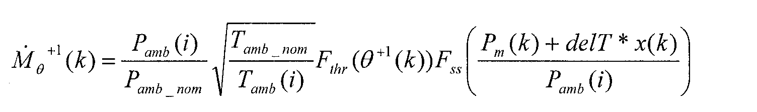
- M ⁇ ⁇ +1 (k) is obtained by adjusting the previously obtained pressure P m (k) in intake manifold 22 with the incremental pressure increase anticipated: where P amb (i) and T amb (i) are the ambient pressure and temperature, respectively, as measured at a time (i) indicative of a slower rate than k, P amb_nom and T amb_nom are previously obtained nominal pressure and temperature values determined under predetermined conditions, F thr is the sonic throttle mass flow and F ss is the sub-sonic flow correction factor accounting for flow reduction as the pressure ration reaches one as set forth in U.S. Patent No. 6,098,602, the entire disclosure of which is incorporated herein by reference.
- M ⁇ ⁇ +1 (k-1 ) is obtained using the previously obtained pressure P m (k) in intake manifold 22 and the estimated throttle plate position ⁇ +1 as follows:
- the equation for the change in the rate of pressure in intake manifold 22 can be modified as follows:
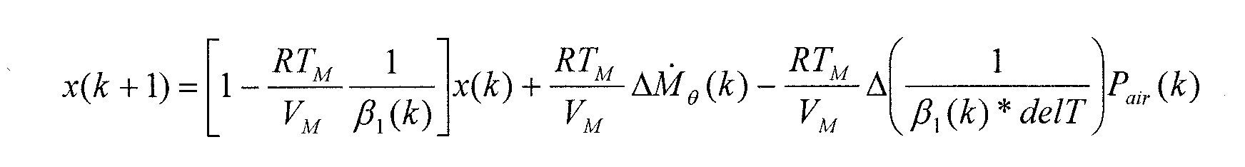
- the inventive method may continue with the step 94 of calculating the cylinder air charge responsive to the rate of change of pressure in intake manifold 22. Because the partial pressure P air (k) of air in the intake manifold and the total pressure P M (k) will increase by the same amount, the pressure ratio across the throttle body 36 will not change significantly and the following approximation may be used: P air +2 (k) P M (k) + delT(x(k) + x(k + 1)) ⁇ P air (k) P M (k)
- a system and method in accordance with the present invention represent a significant improvement as compared to conventional methods and systems for predicting future air charge in an engine cylinder.
- the inventive method and system use the delay between an electronic throttle control (ETC) command and actual throttle positioning responsive to the command to better anticipate the air flow at a cylinder intake port during a future cylinder event.
- ETC electronic throttle control
- the inventive system and method reduce the uncertainty found in conventional systems and methods.
- the inventive system and method predict future air charge without the use of a manifold absolute pressure sensor thereby reducing costs and increasing the flexibility of the system.
Landscapes
- Engineering & Computer Science (AREA)
- Chemical & Material Sciences (AREA)
- Combustion & Propulsion (AREA)
- Mechanical Engineering (AREA)
- General Engineering & Computer Science (AREA)
- Combined Controls Of Internal Combustion Engines (AREA)
- Electrical Control Of Air Or Fuel Supplied To Internal-Combustion Engine (AREA)
Abstract
Description
- The present invention is related to controlling an internal combustion engine and in particular to a method and system for predicting cylinder air charge for a future cylinder event.
- The air-fuel ratio in an internal combustion engine affects both engine emissions and performance. Accordingly, conventional vehicles include systems for controlling the air-fuel ratio in the engine to comply with modern emissions standards, increase fuel economy and improve drivability.
- Conventional engine control systems estimate the mass of air entering each cylinder of the engine (referred to as air charge). These conventional systems typically employ a mass airflow (MAF) sensor or manifold absolute pressure (MAP) sensor to generate an input to an air induction model based on manifold filling and volumetric efficiency. Once the mass of charged air entering the cylinder is determined, the systems attempt to match the mass of charged air with an appropriate amount of injected fuel to maintain an optimal air-fuel ratio.
- Determining the amount of injected fuel at the time of induction into the cylinder, however, presents several problems. There is typically a time delay between the issuance of a fueling command by the control system and injection of the fuel into a cylinder resulting from physical limitations of the fuel delivery system. This is particularly problematic at high engine speeds and loads
where there is less time between engine events. Further, it is desirable to complete fuel injection before the intake valve opens to protect the combustion chamber and to atomize the fuel with the rush of air into the cylinder caused by the initial opening of the intake valve. As a result, estimation of air charge concurrent with actual induction of air into the cylinder occurs too late in the combustion process. - Several systems and methods have been developed that predict the air charge for future cylinder events. For example, in SAE 2000-01-0258, Allen J. Kotwicki et al., "An Algorithm to Compensate for Air Charge Prediction Errors," SAE 2000 World Congress, Detroit, Michigan, March 6-9 2000, a method is disclosed for determining the cylinder air charge for a future cylinder event using a signal from a mass air flow (MAF) sensor. Commonly assigned U.S. Pat. No. 6,170,475 B1, the entire disclosure of which is incorporated herein by reference, discloses a system and method for determining the cylinder air charge one or more cylinder events into the future for an engine having a conventional mechanically controlled throttle plate and a manifold absolute pressure (MAP) sensor. These systems and methods, however, still suffer from a relatively high level of uncertainty in their air charge predictions.
- It is an object of this invention to provide an improved method and system for controlling an engine that will minimize or eliminate one or more of the above-identified deficiencies.
- According to a first aspect of the invention there is provided a method for predicting cylinder air charge in an internal combustion engine for a future cylinder event, said method comprising the steps of calculating a pressure in an intake manifold of said engine, estimating a position for a throttle plate of said engine at least one cylinder event in the future in response to an electronic throttle control command, estimating a rate of change of pressure in said intake manifold responsive to said pressure and said estimated throttle plate position and calculating said cylinder air charge responsive to said rate of change of pressure in said intake manifold.
- Said step of calculating said pressure in said intake manifold may include the substeps of determining an air charge for a cylinder of said engine, determining a partial pressure of air in said intake manifold responsive to said cylinder air charge and determining a partial pressure of recirculated exhaust gas in said intake manifold.
- Said step of estimating a position for said throttle plate may include the substeps of determining a current position of said throttle plate, determining a delay time between first and second cylinder events in said engine and weighting said electronic throttle control command and said current position responsive to said delay time to obtain said estimated throttle plate position.
- Said step of estimating a rate of change in pressure in said intake manifold may include the substep of determining a mass airflow through a throttle of said engine responsive to said pressure and said estimated throttle plate position and determining a rate of change of charged air in said cylinder relative to said pressure in said intake manifold.
- Said future cylinder event may be later in time then said one cylinder event.
- According to a second aspect of the invention there is provided a system for predicting cylinder air charge in an internal combustion engine for a future cylinder event, said system comprising an electronic control unit configured to calculate a pressure in an intake manifold of said engine, to estimate a position for a throttle plate of said engine at least one cylinder event in the future in response to an electronic throttle control command, to estimate a rate of change in pressure of said intake manifold responsive of said pressure and said estimated throttle plate position, and to calculate said cylinder air charge responsive to said rate of change of pressure in said intake manifold.
- Said electronic control unit may be further configured, in calculating said pressure in said intake manifold, to determine an air charge for a cylinder of said engine, to determine a partial pressure of air in said intake manifold responsive to said cylinder air charge, and to determine a partial pressure of recirculated exhaust gas in said intake manifold.
- Said electronic control unit may be further configured, in estimating said position of said throttle plate, to determine a current position of said throttle plate, to determine a delay time between first and second cylinder events in said engine and to weight said electronic throttle control command and said current position responsive to said delay time to obtain said estimated throttle plate position.
- Said electronic control unit may be further configured, in estimating a rate of change in pressure in said intake manifold, to determine a mass airflow through a throttle of said engine responsive to said pressure and said estimated throttle plate position and to determine a rate of change of charged air in said cylinder relative to said pressure in said intake manifold.
- Said future cylinder event may be later in time then said one cylinder event.
- According to a third aspect of the invention there is provided an article of manufacture, comprising a computer storage medium having a computer program encoded therein for predicting cylinder air charge in an internal combustion engine for a future cylinder event, said computer program including code for calculating a pressure in an intake manifold of said engine, code for estimating a position for a throttle plate of said engine at least one cylinder event in the future in response to an electronic throttle control command, code for estimating a rate of change of pressure in said intake manifold responsive to said pressure and said estimated throttle plate position and code for calculating said cylinder air charge responsive to said rate of change of pressure in said intake manifold.
- Said code for calculating said pressure in said intake manifold may include code for determining an air charge for a cylinder of said engine, code for determining a partial pressure of air in said intake manifold responsive to said cylinder air charge and code for determining a partial pressure of recirculated exhaust gas in said intake manifold.
- Said code for estimating said position of said throttle plate may include code for determining a current position of said throttle plate, code for determining a delay time between first and second cylinder events in said engine and code for weighting said electronic throttle control command and said current position responsive to said delay time to obtain said estimated throttle plate position.
- Said code for estimating a rate of change in pressure in said intake manifold may include code for determining a mass airflow through a throttle of said engine responsive to said pressure and said estimated throttle plate position and code for determining a rate of change of charged air in said cylinder relative to said pressure in said intake manifold.
- Said future cylinder event may be later in time then said one cylinder event.
- Said article of manufacture may be an electronic control unit.
- The present invention therefore represents an improvement as compared to conventional systems and method for predicting cylinder air charge for future cylinder events in that the inventive system and method use the delay between an electronic throttle control (ETC) command and actual throttle positioning responsive to the command to better anticipate the air flow at a cylinder intake port during a future cylinder event. In this manner, the inventive system and method reduce the uncertainty found in conventional systems and methods. Further, the inventive system and method predict future air charge without the use of a manifold absolute pressure sensor.
- The invention will now be described by way of example with reference to the accompanying drawing of which:-
- Figure 1 is a schematic diagram illustrating an internal combustion engine incorporating a system for predicting cylinder air charge for a future cylinder event of the engine in accordance with the present invention; and
- Figure 2 is a flow chart diagram illustrating a method for predicting cylinder air charge for a future cylinder event in an internal combustion engine in accordance with the present invention.
-
- Referring now to the drawings wherein like reference numerals are used to identify identical components in the various views, Figure 1 illustrates an
internal combustion engine 10 and asystem 12 in accordance with the present invention for controllingengine 10. In particular,system 12 controls engine to regulate the air fuel ratio inengine 10 during combustion in order to control emissions and improve performance ofengine 10. -
Engine 10 is designed for use in a motor vehicle. It should be understood, however, thatengine 10 may be used in a wide variety of applications.Engine 10 provides motive energy to a motor vehicle or other device and is conventional in the art.Engine 10 may define a plurality of combustion chambers or cylinders 14 and may also include a plurality ofpistons 16 coolant passages 18, athrottle assembly 20, an intake manifold 22, anexhaust manifold 24, and engine gas recirculation (EGR)system 26,fuel injectors 28,intake valves 30,exhaust valves 32, and acamshaft 34. Engine may also include spark plugs (not shown) and an ignition system (not shown) as is known in the art. - Cylinders 14 provide a space for combustion of an air/fuel mixture to occur and are conventional in the art. In the illustrated embodiment, only one cylinder 14 is shown. It will be understood, however, that
engine 10 may define a plurality of cylinders 14 and that the number of cylinders 14 may be varied without departing from the scope of the present invention. -
Pistons 16 are coupled to a crankshaft (not shown) and drive the crankshaft responsive to an expansion force of the air fuel mixture in cylinders 14 during combustion. Pistons 16 are conventional in the art and apiston 16 may be disposed in each cylinder 14. - Coolant passages 18 provide a means for routing a heat transfer medium, such as a conventional engine coolant, through
engine 10 to transfer heat from cylinders 14 to a location external toengine 10. Passages 18 are conventional in the art. -
Throttle assembly 20 controls the amount of air delivered to intake manifold 22 and cylinders 14.Assembly 20 is conventional in the art and may include a throttle body 36 and an electronically controlledthrottle plate 38 disposed therein for regulating the amount of airflow through body 36 to manifold 22.Plate 38 may be driven by an electronically controlledactuator 40. A sensor 42 may provide a feedback signal indicative of the actual position ofplate 38 to implement closed loop control ofplate 38. - Intake manifold 22 provides a means for delivering charged air to cylinders 14. Manifold 22 is conventional in the art. An inlet port is disposed between manifold 22 and each cylinder 14.
-
Exhaust manifold 24 is provided to vent exhaust gases from cylinders 14 after each combustion event. Manifold 24 is also conventional in the art. An exhaust port is disposed betweenmanifold 24 and each cylinder 14. -
EGR system 26 is provided to return a portion of the exhaust gases to cylinders 14 in order to reduce emissions of combustion by-products.EGR system 24 includes apassage 44 that extends fromexhaust manifold 24 to intake manifold 22 and anEGR valve 46 that may be disposed withinpassage 44 to control the delivery of recirculated exhaust gases to intake manifold 22. -
Fuel injectors 28 are provided to deliver fuel in controlled amounts to cylinders 14 and are conventional in the art. Although only onefuel injector 28 is shown in the illustrated embodiment, it will again be understood thatengine 10 will includeadditional fuel injectors 28 for delivering fuel to other cylinders 14 inengine 10. -
Intake valves 30 open and close each intake port to control the delivery of air to the respective cylinder 14.Intake valves 30 are conventional in the art. Although only oneintake valve 30 is shown in the illustrated embodiment, it should be understood thatmultiple intake valves 30 may be used for each cylinder 14. -
Exhaust valves 32 open and close each exhaust port to control the venting of exhaust gases from the respective cylinder 14 and are also conventional in the art. Again, although only oneexhaust valve 32 is shown in the illustrated embodiment, it should be understood thatmultiple exhaust valves 32 may be used for each cylinder 14. -
Camshaft 34 is provided to control the movement ofintake valves 30 andexhaust valves 32 and is conventional in the art. It should be understood that multiple camshafts may be used to controlvalves -
System 12 is provided to controlengine 10. In particular,system 12 is provided to predict the air charge for a future cylinder event in one or more of the cylinders 14 ofengine 10.System 12 may include an electronic control unit (ECU) 48. -
ECU 48 is provided to controlengine 10.ECU 48 may comprise a programmable microprocessor or microcontroller or may comprise an application specific integrated circuit (ASIC).ECU 48 may include a central processing unit (CPU) 50 and an input/output (I/O)interface 52. Throughinterface 52,ECU 48 may receive a plurality of input signals including signals generated by sensor 42 and conventional sensors such as a profile ignition pickup (PIP)sensor 54, a engine coolant temperature sensor 56, a cylinder identification (CID)sensor 58, anair temperature sensor 60, a mass air flow (MAF)sensor 62, and an exhaustgas oxygen sensor 64. Also throughinterface 52,ECU 48 may generate a plurality of output signals including one or more signals used to controlfuel injectors 28,throttle plate 38 andEGR valve 46.ECU 58 may also include one or more memories including, for example, Read Only Memory (ROM) 66, Random Access Memory (RAM) 68, and a Keep Alive Memory (KAM) 70 to retain information when the ignition key is turned off. - Referring now to Figure 2 a method in accordance with one embodiment of the present invention for predicting cylinder air charge for a future cylinder event of
engine 10 will be described in detail. The inventive method or algorithm may be implemented bysystem 12 whereinECU 48 is configured to perform several steps of the method by programming instruction or code (i.e., software). The instructions may be encoded on a computer storage medium such as a conventional diskette or CD-ROM and may be copied into one ofmemories ECU 48 using conventional computing devices and methods. - The inventive method begins with the
step 72 of calculating a pressure in intake manifold 22 ofengine 10 andstep 72 includesseveral substeps - In
substep 74, the air charge Mcyl(k) for a cylinder 14 ofengine 10 is determined.ECU 48 may determine the cylinder air charge Mcyl(k) using known methods based on the mass air flow into intake manifold 22 as detected by massair flow sensor 62. Commonly assigned U.S. Pat. No. 5,331,936, the entire disclosure of which is incorporated herein by reference, discloses a method and apparatus for inferring the actual air charge in an internal combustion engine during transient conditions. - In
substep 76, a partial pressure of air Pair (k) in intake manifold 22 is determined responsive to the cylinder air charge Mcyl (k).ECU 48 may determine the partial pressure of air Pair (k) as follows: - In
substep 78, a partial pressure of recirculated exhaust gas Pegr(k) in intake manifold 22 is determined. - The
ECU 48 determines the partial pressure of air Pegr(k) as follows:where Pegr(k-1) is the partial pressure of recirculated exhaust gas for a prior cylinder event, delT is the time period between cylinder events, R is the specific gas constant, Tm is the temperature in the intake manifold 22, Vm is the volume of intake manifold 22, M ˙egr(k) is the flow of recirculated exhaust gas into intake manifold 22 (which may be calculated as set forth in U.S. Patent No. 6,098,602, the entire disclosure of which is incorporated herein by reference), Ftemp(Tamb, Teng) a function used to adjust the equation for the effects of ambient engine temperature differences between actual operating conditions and the original engine mapping conditions, and β1, β2, Pamb(i), Pamb_nom (i), and Pm(k-1) are as set forth hereinabove. The total intake manifold pressure Pm(k) may then be calculated as follows:
- Referring again to Figure 2, the inventive method continues with the
step 80 of estimating a position ofthrottle plate 38 at least one cylinder event in the future and thestep 80 includesseveral substeps - In
substep 82, the current position tp_meas(k) ofthrottle plate 38 is determined.ECU 48 may determine the position tp_meas(k) using the signal generated by sensor 42. - In
substep 84, the current delay time delT between any two cylinder events inengine 10 is determined.ECU 48 may determine the delay time delT responsive to engine speed as indicated bysensor 54 or in other ways customary in the art. - In
substep 86, an electronic throttle control command tp_com (k) and the measured position ofthrottle plate 38 tp_meas (k) are weighted responsive to the delay time delT to obtain the estimated throttle plate position one cylinder even in the future as follows:
- The present invention takes advantage of the delay ETC_delay between issuance of the electronic throttle control command tp_com (k) and the actual positioning of
plate 38 responsive to the command. At low engine speeds, the delay delT between cylinder events is relatively large which favors use of the commanded throttle position tp_com (k) in estimating future throttle position. At higher engine speeds, however, cylinder events occur much more quickly and often in less time than ETC_delay, thereby favoring use of the measured throttle plate position tp_meas (k). - Referring again to Figure 2, the inventive method may continue with the step 88 of estimating a rate of change of pressure in intake manifold 22 responsive to the previously calculated pressure Pm(k) in intake manifold 22 and the estimated throttle plate position +1(k). The rate of change of pressure in intake manifold 22 between any two cylinder events may be characterized as follows:
- The partial pressure of air Pair in intake manifold 22 may be obtained using the ideal gas law:
- By differentiating both sides of the equation for Pair and ignoring the derivative of the offset term

- This equation may be discretized and combined with the equation for the rate of change of pressure in intake manifold 22 to obtain:
- Step 88 may include
substeps substep 90, the mass airflow through throttle body 36 ofengine 10 is determined responsive to the intake manifold pressure MP (k) and the estimated throttle plate position +1. Instep 92, the rate of change in pressure of the charged air in cylinder 14 relative to the pressure in intake manifold 22 is determined. - In particular, the term ΔM ˙ +1 (k) representing a change in mass air flow through throttle body 36--in the above equation for the change in the rate of pressure in intake manifold 22 may be characterized as follows:
- The rate of change in the slope that relates the intake manifold pressure and cylinder air-flow may be characterized as follows:

- The values for M +1 (k+ 1) and the future engine speed are not yet available. Accordingly, the rate of change of speed of
engine 10 is assumed to be constant between any two cylinder events and the above two equations are modified as follows:
- The term M ˙ +1(k) is obtained by adjusting the previously obtained pressure Pm(k) in intake manifold 22 with the incremental pressure increase anticipated:where Pamb (i) and Tamb (i) are the ambient pressure and temperature, respectively, as measured at a time (i) indicative of a slower rate than k, Pamb_nom and Tamb_nom are previously obtained nominal pressure and temperature values determined under predetermined conditions, Fthr is the sonic throttle mass flow and Fss is the sub-sonic flow correction factor accounting for flow reduction as the pressure ration reaches one as set forth in U.S. Patent No. 6,098,602, the entire disclosure of which is incorporated herein by reference.
- The term M ˙ +1(k-1) is obtained using the previously obtained pressure Pm(k) in intake manifold 22 and the estimated throttle plate position +1 as follows:

- Using these equations, the equation for the change in the rate of pressure in intake manifold 22 can be modified as follows:

- Referring again to Figure 2, the inventive method may continue with the
step 94 of calculating the cylinder air charge responsive to the rate of change of pressure in intake manifold 22. Because the partial pressure Pair(k) of air in the intake manifold and the total pressure PM(k) will increase by the same amount, the pressure ratio across the throttle body 36 will not change significantly and the following approximation may be used: - This equation may be rearranged in the following manner for cylinder air charge:
- Multiplying both sides of the above equation by delT and subtracting
- A system and method in accordance with the present invention represent a significant improvement as compared to conventional methods and systems for predicting future air charge in an engine cylinder. In particular, the inventive method and system use the delay between an electronic throttle control (ETC) command and actual throttle positioning responsive to the command to better anticipate the air flow at a cylinder intake port during a future cylinder event. In this manner, the inventive system and method reduce the uncertainty found in conventional systems and methods. Further, the inventive system and method predict future air charge without the use of a manifold absolute pressure sensor thereby reducing costs and increasing the flexibility of the system.
- Although the invention has been described herein with reference to certain exemplary embodiments it is not so limited and various modifications or alternative embodiments could be made without departing from the scope of the invention.
Claims (11)
- A method for predicting cylinder air charge in an internal combustion engine (10) for a future cylinder event characterised in that said method comprises the steps of calculating a pressure in an intake manifold (22) of said engine (10), estimating a position for a throttle plate (38) of said engine (10) at least one cylinder event in the future in response to an electronic throttle control command, estimating a rate of change of pressure in said intake manifold (22) responsive to said pressure and said estimated throttle plate position and calculating said cylinder air charge responsive to said rate of change of pressure in said intake manifold (22).
- A method as claimed in claim 1 wherein said step of calculating said pressure in said intake manifold (22) includes the substeps of determining an air charge for a cylinder (14) of said engine (10), determining a partial pressure of air in said intake manifold (22) responsive to said cylinder air charge and determining a partial pressure of recirculated exhaust gas in said intake manifold (22).
- A method as claimed in claim 1 or in claim 2 wherein said step of estimating a position for said throttle plate (38) includes the substeps of determining a current position of said throttle plate (38), determining a delay time between first and second cylinder events in said engine (10), and weighting said electronic throttle control command and said current position responsive to said delay time to obtain said estimated throttle plate position.
- A method as claimed in any of claims 1 to 3 wherein said step of estimating a rate of change in pressure in said intake manifold (22) includes the substep of determining a mass airflow through a throttle of said engine (10) responsive to said pressure and said estimated throttle plate position and determining a rate of change of charged air in said cylinder (14) relative to said pressure in said intake manifold (22).
- A method as claimed in any of claims 1 to 4 wherein said future cylinder event is later in time then said one cylinder event.
- A system (12) for predicting cylinder air charge in an internal combustion engine (10) for a future cylinder event characterised in that said system comprises an electronic control unit (48) configured to calculate a pressure in an intake manifold (22) of said engine (10), to estimate a position for a throttle plate (38) of said engine (10) at least one cylinder event in the future in response to an electronic throttle control command, to estimate a rate of change in pressure of said intake manifold (22) responsive of said pressure and said estimated throttle plate position, and to calculate said cylinder air charge responsive to said rate of change of pressure in said intake manifold (22).
- A system as claimed in claim 6 wherein said electronic control unit (48) is further configured, in calculating said pressure in said intake manifold (22), to determine an air charge for a cylinder (14) of said engine (10), to determine a partial pressure of air in said intake manifold (22) responsive to said cylinder air charge, and to determine a partial pressure of recirculated exhaust gas in said intake manifold (22).
- A system as claimed in claim 6 or in claim 7 wherein said electronic control unit (48) is further configured, in estimating said position of said throttle plate (38), to determine a current position of said throttle plate (38), to determine a delay time between first and second cylinder events in said engine (10), and to weight said electronic throttle control command and said current position responsive to said delay time to obtain said estimated throttle plate position.
- A system as claimed in any of claims 6 to 8 wherein said electronic control unit (48) is further configured, in estimating a rate of change in pressure in said intake manifold (22), to determine a mass airflow through a throttle of said engine (10) responsive to said pressure and said estimated throttle plate position and to determine a rate of change of charged air in said cylinder (14) relative to said pressure in said intake manifold (22).
- A system as claimed in any of claims 6 to 9 wherein said future cylinder event is later in time then said one cylinder event.
- An article of manufacture comprising a computer storage medium (50, 70, 68) having a computer program encoded therein for predicting cylinder air charge in an internal combustion engine (10) for a future cylinder event characterised in that the computer program includes code for calculating a pressure in an intake manifold (22) of said engine (10), code for estimating a position for a throttle plate (38) of said engine at least one cylinder event in the future in response to an electronic throttle control command, code for estimating a rate of change of pressure in said intake manifold (22) responsive to said pressure and said estimated throttle plate position and code for calculating said cylinder air charge responsive to said rate of change of pressure in said intake manifold (22).
Applications Claiming Priority (2)
| Application Number | Priority Date | Filing Date | Title |
|---|---|---|---|
| US210547 | 1988-06-23 | ||
| US10/210,547 US6708102B2 (en) | 2002-08-01 | 2002-08-01 | Method and system for predicting cylinder air charge in an internal combustion engine for a future cylinder event |
Publications (2)
| Publication Number | Publication Date |
|---|---|
| EP1387068A2 true EP1387068A2 (en) | 2004-02-04 |
| EP1387068A3 EP1387068A3 (en) | 2006-09-06 |
Family
ID=30115240
Family Applications (1)
| Application Number | Title | Priority Date | Filing Date |
|---|---|---|---|
| EP03102172A Withdrawn EP1387068A3 (en) | 2002-08-01 | 2003-07-15 | Method and system for predicting cylinder air charge in an internal combustion engine |
Country Status (2)
| Country | Link |
|---|---|
| US (1) | US6708102B2 (en) |
| EP (1) | EP1387068A3 (en) |
Families Citing this family (27)
| Publication number | Priority date | Publication date | Assignee | Title |
|---|---|---|---|---|
| JP3898114B2 (en) * | 2002-11-01 | 2007-03-28 | 本田技研工業株式会社 | Intake air amount estimation method, estimation device, intake air amount control method and control device for internal combustion engine |
| US6851304B2 (en) * | 2003-01-28 | 2005-02-08 | Ford Global Technologies, Llc | Air estimation approach for internal combustion engine control |
| US7275426B2 (en) * | 2005-04-01 | 2007-10-02 | Wisconsin Alumni Research Foundation | Internal combustion engine control system |
| US7676315B2 (en) * | 2006-03-07 | 2010-03-09 | Ford Global Technologies, Llc | Vehicle response during vehicle acceleration conditions |
| EP1995768A4 (en) | 2006-03-13 | 2013-02-06 | Nikon Corp | EXPOSURE APPARATUS, MAINTENANCE METHOD, EXPOSURE METHOD, AND DEVICE MANUFACTURING METHOD |
| US7380447B2 (en) * | 2006-06-10 | 2008-06-03 | Ford Global Technologies. Llc | Method and system for transient airflow compensation in an internal combustion engine |
| JP5594233B2 (en) * | 2011-06-07 | 2014-09-24 | 三菱自動車工業株式会社 | Engine control device |
| DE102017112565A1 (en) | 2016-06-09 | 2017-12-14 | Ford Global Technologies, Llc | SYSTEM FOR RESETTING THE DISCONNECTED CYLINDER |
| US10024256B2 (en) * | 2016-06-09 | 2018-07-17 | Ford Global Technologies, Llc | System and method for intake manifold pressure control |
| DE102017112689A1 (en) | 2016-06-09 | 2017-12-14 | Ford Global Technologies, Llc | System and method for compensating the wear of the cylinder deactivation |
| DE102017112643A1 (en) | 2016-06-09 | 2017-12-14 | Ford Global Technologies, Llc | SYSTEM AND METHOD FOR SELECTING A CYLINDER DEACTIVATION MODE |
| CN107489553B (en) | 2016-06-09 | 2021-12-10 | 福特环球技术公司 | System and method for controlling fuel for reactivating engine cylinders |
| DE102017112671A1 (en) | 2016-06-09 | 2017-12-14 | Ford Global Technologies, Llc | System and method for controlling the pressure in the engine intake manifold |
| DE102017112317A1 (en) | 2016-06-09 | 2017-12-14 | Ford Global Technologies, Llc | SYSTEM AND METHOD FOR IMPROVING CYLINDER SHUT-OFF |
| DE102017112690B4 (en) | 2016-06-09 | 2024-12-12 | Ford Global Technologies, Llc | System for controlling engine torque while simultaneously shutting off engine cylinders |
| DE102017112627A1 (en) | 2016-06-09 | 2017-12-14 | Ford Global Technologies, Llc | SYSTEM AND METHOD FOR TURNING ON MOTOR CYLINDERS |
| DE102017112680B4 (en) | 2016-06-09 | 2025-03-20 | Ford Global Technologies, Llc | System and method for controlling cylinder mode change activity |
| CN107489582B (en) | 2016-06-09 | 2021-12-31 | 福特环球技术公司 | System and method for determining engine knock |
| DE102017112656B4 (en) | 2016-06-09 | 2025-05-08 | Ford Global Technologies, Llc | System and method for regulating engine knock |
| DE102017112631A1 (en) | 2016-06-09 | 2017-12-14 | Ford Global Technologies, Llc | CONFIGURATION OF ACTUATED CYLINDER FOR ONE ENGINE, INCLUDING SHUT-OFF ENGINE CYLINDER |
| DE102017112670A1 (en) | 2016-06-09 | 2017-12-14 | Ford Global Technologies, Llc | Cylinder deactivation control for powertrain braking |
| DE102017112566A1 (en) | 2016-06-09 | 2017-12-14 | Ford Global Technologies, Llc | SYSTEM AND METHOD FOR OPERATING A MACHINE OIL PUMP |
| DE102017112660A1 (en) | 2016-06-09 | 2017-12-14 | Ford Global Technologies, Llc | SYSTEM AND METHOD FOR REGULATING ENGINE BUTTING OF A VARIABLE LIFTING ENGINE |
| CN107489536B (en) | 2016-06-09 | 2022-05-10 | 福特环球技术公司 | System for deactivating engine cylinders |
| DE102017112638A1 (en) | 2016-06-09 | 2017-12-14 | Ford Global Technologies, Llc | SYSTEM AND METHOD FOR ADJUSTING THE PRESSURE IN THE INTAKE MANIFOLD |
| JP6749297B2 (en) * | 2017-08-24 | 2020-09-02 | 日立オートモティブシステムズ株式会社 | Internal combustion engine controller |
| CN114962047B (en) * | 2021-08-26 | 2023-05-26 | 长城汽车股份有限公司 | Method for estimating relative charge of engine and vehicle |
Citations (1)
| Publication number | Priority date | Publication date | Assignee | Title |
|---|---|---|---|---|
| US6170475B1 (en) | 1999-03-01 | 2001-01-09 | Ford Global Technologies, Inc. | Method and system for determining cylinder air charge for future engine events |
Family Cites Families (12)
| Publication number | Priority date | Publication date | Assignee | Title |
|---|---|---|---|---|
| JPS5848725A (en) * | 1981-09-18 | 1983-03-22 | Toyota Motor Corp | Fuel-injection engine |
| JPH01177432A (en) * | 1987-12-28 | 1989-07-13 | Fuji Heavy Ind Ltd | Fuel injection control device for internal combustion engine |
| US5297064A (en) * | 1991-04-01 | 1994-03-22 | General Motors Corporation | Sensor lag compensation |
| JPH04311643A (en) * | 1991-04-10 | 1992-11-04 | Hitachi Ltd | How to calculate the amount of air flowing into engine cylinders |
| US5159914A (en) | 1991-11-01 | 1992-11-03 | Ford Motor Company | Dynamic fuel control |
| US5357932A (en) | 1993-04-08 | 1994-10-25 | Ford Motor Company | Fuel control method and system for engine with variable cam timing |
| DE4401828B4 (en) | 1994-01-22 | 2004-02-19 | Robert Bosch Gmbh | Method and device for predicting a future load signal in connection with the control of an internal combustion engine |
| JPH08326593A (en) * | 1995-06-02 | 1996-12-10 | Hitachi Ltd | Air-fuel ratio control device for engine and vehicle equipped with the engine |
| DE19728112A1 (en) * | 1997-07-02 | 1999-01-07 | Bosch Gmbh Robert | System for operating an internal combustion engine, in particular a motor vehicle |
| US6089082A (en) | 1998-12-07 | 2000-07-18 | Ford Global Technologies, Inc. | Air estimation system and method |
| US6460409B1 (en) * | 2000-05-13 | 2002-10-08 | Ford Global Technologies, Inc. | Feed-forward observer-based control for estimating cylinder air charge |
| US6651492B2 (en) * | 2001-11-01 | 2003-11-25 | Ford Global Technologies, Llc | Method and system for controlling partial pressure of air in an intake manifold of an engine |
-
2002
- 2002-08-01 US US10/210,547 patent/US6708102B2/en not_active Expired - Fee Related
-
2003
- 2003-07-15 EP EP03102172A patent/EP1387068A3/en not_active Withdrawn
Patent Citations (1)
| Publication number | Priority date | Publication date | Assignee | Title |
|---|---|---|---|---|
| US6170475B1 (en) | 1999-03-01 | 2001-01-09 | Ford Global Technologies, Inc. | Method and system for determining cylinder air charge for future engine events |
Also Published As
| Publication number | Publication date |
|---|---|
| EP1387068A3 (en) | 2006-09-06 |
| US6708102B2 (en) | 2004-03-16 |
| US20040024517A1 (en) | 2004-02-05 |
Similar Documents
| Publication | Publication Date | Title |
|---|---|---|
| US6708102B2 (en) | Method and system for predicting cylinder air charge in an internal combustion engine for a future cylinder event | |
| US6170475B1 (en) | Method and system for determining cylinder air charge for future engine events | |
| EP1312784A1 (en) | A method and system for controlling an internal combustion engine | |
| EP1528241A2 (en) | Estimation of intake gas temperature in internal combustion engine | |
| US20050166900A1 (en) | Engine control to compensate for fueling dynamics | |
| US7121233B2 (en) | Control apparatus for an internal combustion engine | |
| US5597951A (en) | Intake air amount-estimating apparatus for internal combustion engines | |
| WO1998005856A1 (en) | Control device for cylinder injection type spark-ignition internal combustion engines | |
| US6553964B2 (en) | Coordinated valve timing and throttle control for controlling intake air | |
| US5809969A (en) | Method for processing crankshaft speed fluctuations for control applications | |
| EP1104843B1 (en) | System and method for controlling intake air by variable valve timing | |
| CN119096043A (en) | Pre-chamber spark control with two ignition sources | |
| US6738706B2 (en) | Method for estimating engine parameters | |
| EP1310650B1 (en) | A Method and System for Engine Control during Transient Operation | |
| US6394065B1 (en) | Method for operating an internal combustion engine | |
| US6751567B2 (en) | Electronic throttle plate index position determination for improved airflow correlation over various temperature conditions | |
| US6736105B1 (en) | Control system for direct injection spark ignition engines with a cam profile switching device | |
| JP3307306B2 (en) | Combustion system control device for internal combustion engine | |
| US6970780B2 (en) | System and method for transitioning between engine device schedules based on engine operating condition | |
| JP3114352B2 (en) | Air-fuel ratio control device for internal combustion engine | |
| JPH11153058A (en) | Engine control device with idle intake pressure learning function | |
| EP1314876A1 (en) | A Method and System for Controlling the Fuelling of an Engine | |
| US7690249B2 (en) | Method for detecting a jammed charge movement flap of an internal combustion engine | |
| JPH08326578A (en) | Combustion control device for diesel engine | |
| CN116981841A (en) | Internal combustion engine control device |
Legal Events
| Date | Code | Title | Description |
|---|---|---|---|
| PUAI | Public reference made under article 153(3) epc to a published international application that has entered the european phase |
Free format text: ORIGINAL CODE: 0009012 |
|
| AK | Designated contracting states |
Kind code of ref document: A2 Designated state(s): AT BE BG CH CY CZ DE DK EE ES FI FR GB GR HU IE IT LI LU MC NL PT RO SE SI SK TR |
|
| AX | Request for extension of the european patent |
Extension state: AL LT LV MK |
|
| RAP1 | Party data changed (applicant data changed or rights of an application transferred) |
Owner name: FORD GLOBAL TECHNOLOGIES, LLC. |
|
| PUAL | Search report despatched |
Free format text: ORIGINAL CODE: 0009013 |
|
| AK | Designated contracting states |
Kind code of ref document: A3 Designated state(s): AT BE BG CH CY CZ DE DK EE ES FI FR GB GR HU IE IT LI LU MC NL PT RO SE SI SK TR |
|
| AX | Request for extension of the european patent |
Extension state: AL LT LV MK |
|
| 17P | Request for examination filed |
Effective date: 20070202 |
|
| AKX | Designation fees paid |
Designated state(s): DE GB |
|
| 17Q | First examination report despatched |
Effective date: 20071127 |
|
| STAA | Information on the status of an ep patent application or granted ep patent |
Free format text: STATUS: THE APPLICATION IS DEEMED TO BE WITHDRAWN |
|
| 18D | Application deemed to be withdrawn |
Effective date: 20130101 |
|
| R18D | Application deemed to be withdrawn (corrected) |
Effective date: 20130201 |