EP1387048B1 - Rocking lever for valve drive with variable lift - Google Patents
Rocking lever for valve drive with variable lift Download PDFInfo
- Publication number
- EP1387048B1 EP1387048B1 EP03015068A EP03015068A EP1387048B1 EP 1387048 B1 EP1387048 B1 EP 1387048B1 EP 03015068 A EP03015068 A EP 03015068A EP 03015068 A EP03015068 A EP 03015068A EP 1387048 B1 EP1387048 B1 EP 1387048B1
- Authority
- EP
- European Patent Office
- Prior art keywords
- roller element
- roller
- lever
- stroke
- hand
- Prior art date
- Legal status (The legal status is an assumption and is not a legal conclusion. Google has not performed a legal analysis and makes no representation as to the accuracy of the status listed.)
- Expired - Lifetime
Links
Images

Classifications
-
- F—MECHANICAL ENGINEERING; LIGHTING; HEATING; WEAPONS; BLASTING
- F01—MACHINES OR ENGINES IN GENERAL; ENGINE PLANTS IN GENERAL; STEAM ENGINES
- F01L—CYCLICALLY OPERATING VALVES FOR MACHINES OR ENGINES
- F01L13/00—Modifications of valve-gear to facilitate reversing, braking, starting, changing compression ratio, or other specific operations
- F01L13/0005—Deactivating valves
-
- F—MECHANICAL ENGINEERING; LIGHTING; HEATING; WEAPONS; BLASTING
- F01—MACHINES OR ENGINES IN GENERAL; ENGINE PLANTS IN GENERAL; STEAM ENGINES
- F01L—CYCLICALLY OPERATING VALVES FOR MACHINES OR ENGINES
- F01L13/00—Modifications of valve-gear to facilitate reversing, braking, starting, changing compression ratio, or other specific operations
- F01L13/0015—Modifications of valve-gear to facilitate reversing, braking, starting, changing compression ratio, or other specific operations for optimising engine performances by modifying valve lift according to various working parameters, e.g. rotational speed, load, torque
- F01L13/0063—Modifications of valve-gear to facilitate reversing, braking, starting, changing compression ratio, or other specific operations for optimising engine performances by modifying valve lift according to various working parameters, e.g. rotational speed, load, torque by modification of cam contact point by displacing an intermediate lever or wedge-shaped intermediate element, e.g. Tourtelot
- F01L2013/0068—Modifications of valve-gear to facilitate reversing, braking, starting, changing compression ratio, or other specific operations for optimising engine performances by modifying valve lift according to various working parameters, e.g. rotational speed, load, torque by modification of cam contact point by displacing an intermediate lever or wedge-shaped intermediate element, e.g. Tourtelot with an oscillating cam acting on the valve of the "BMW-Valvetronic" type
-
- F—MECHANICAL ENGINEERING; LIGHTING; HEATING; WEAPONS; BLASTING
- F01—MACHINES OR ENGINES IN GENERAL; ENGINE PLANTS IN GENERAL; STEAM ENGINES
- F01L—CYCLICALLY OPERATING VALVES FOR MACHINES OR ENGINES
- F01L2305/00—Valve arrangements comprising rollers
Definitions
- the invention relates to a pivoting lever for a variable-stroke valve drive according to the features in the preamble of patent claim 1.
- valve drive device for variable stroke adjustment of a gas exchange valve of an internal combustion engine is described.
- the gas exchange valve with the interposition of a transmission element with a movable about a rotation axis roller operatively connected to a, a Leerhubkurve and a lift cam comprehensive control path, which is arranged in an end region of a lifting operation of the gas exchange valve controlled by a cam of a camshaft pivot lever.
- the play-free by means of a spring on a roller cam associated with the pivot lever is supported at the other end to the variable stroke position of the gas exchange valve via a controlled by means of an adjustment position variable and fixable swing fulcrum along a circular path.
- a purely rotational movement or pure pivoting movement of the pivot lever about its swing pivot point at a reduced stroke of the gas exchange valve is arranged on a housing part of the engine circular path as a backdrop with a radius "R" about the axis of rotation of the role of the transmission element for controlled positionally variable support provided the pivot lever.
- first roller element 4 Since the first roller element 4 is supported both on the adjusting device 11 and on the slide track, relatively high frictional forces can occur during adjustment of the pivot lever, whereby increased wear can occur.
- EP 1 096 115 and DE 1 0016 103 show further embodiments of a pivot lever for variable-stroke valve trains.
- Object of the present invention is to show friction-reducing measures for a generic pivoting lever.
- roller element into two separate roller elements means that advantageously the first roller element or the second roller element is in operative connection only with either the slide or with the adjusting unit. Production-related tolerances in the production of rolls can be better compensated by this arrangement, whereby the internal friction and thus the wear is reduced.
- the bearing tolerances of the first roller element and the second roller element whereby production-related tolerances can be even better balanced.
- the complex configuration according to the claims 3 and 4 has the lowest friction losses and thus the lowest wear during operation of the pivot lever.
- the embodiment according to claim 5 has the best power distribution and the lowest friction during operation, which in turn increases the service life, minimizes internal friction, wear and fuel consumption of the internal combustion engine.
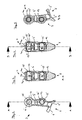
- Fig. 1 shows a variable-stroke valve drive 2, which is arranged in a cylinder head 1 shown in the beginning.
- the stroke variable valve train 2 consists essentially of a pivot lever 3, with a roller element 4 and a swing pivot 4 ', a third roller element 13, and a link 5 with a slide track 5', an intermediate element 7, a gas exchange valve 8, a cam 9, the
- the pivot lever 3 is supported on the one hand via the roller element 4 on the link path 5 'of the link 5 and on the other hand with a control track 6, which consists of a Leerhubkurve 6' and a lift curve 6 "on the intermediate element 7.
- the intermediate element 7 is a roller rocker arm, the roller of which is rotatable about an axis of rotation 12.
- the axis of rotation 12 is simultaneously the center of the rocker track 5 'in a zero stroke position on a lash adjuster 14, here a hydraulic lash adjuster, and on the other hand on the gas exchange valve 8 from.
- the third roller element 13 is arranged parallel to the first roller element 4 on the pivot lever 3.
- Fig. 2 shows the side view of a pivot lever 3 for the first and the second embodiment.
- the pivot lever 3 consists of an approximately box-shaped housing 3 ', which on one end of the control track 6, with the Leerhubkurve 6' and the lifting cam 6 "and at the opposite end a first bore 15 which is aligned normal to the control track 6 has A first bolt 16 is located radially in the first bore 15.
- the roller element 4 is arranged radially around the first bolt 16.
- roller element 4 Between the roller element 4 and the control track 6 there is a second bore 15 'in which a second bolt 16' is parallel to the bolt
- the third roller element 13 is rotatably mounted on the outer circumference around the pin 16 ', and a section AA is drawn through the axes of the first bore 15 and the second bore 15' FIG. 3 and FIG. 4 for each embodiment.
- Fig. 3 shows a section through the plane AA for a first embodiment of the pivot lever 3.
- a rolling bearing 17 is arranged radially on the outer circumference about the first pin 16. Radially about this roller bearing 17 is rotatably the roller element 4, mounted within the housing 3 '.
- the roller element 4 is divided into two first roller elements 4a and a second roller element 4b.
- the roller element 4b extends in the axial direction over the entire length of the rolling bearing 17, corresponding to an internal dimension, not shown, of the housing 3 '.
- Radially on the outer circumference of the first roller member 4b, the two second roller elements 4a are arranged rotatably.
- the two first roller elements 4a form a sliding bearing with the second roller element 4b.
- first roller element 4a may be provided, which then extends in axial alignment over approximately one half of the second roller element 4b or in the middle of the second roller element 4b is arranged.
- a roller bearing of the first roller element 4a on the second roller element 4b is also possible.
- Fig. 4 shows the section through the pivot lever 3 in the plane AA for a second embodiment.
- two first roller elements 4a and a second roller element 4b bounded by the housing 3 ', rotatably mounted.
- These first roller elements 4a and the second roller element 4b are arranged next to the first embodiment in the axial direction next to each other and each have their own rolling bearing 17 ', 17 ", 17"' opposite the first pin 16.
- the first roller element 4a in operative connection with the adjusting device 11
- the second roller element 4b is in operative connection with the slide track 5 'of the link 5.
- a section BB is drawn, which is rotated in relation to the section AA by 90 °.
- first roller element 4a may be provided.
- first roller element 4a and the second roller element 4b are again adjacent to one another in the axial direction of the first pin 16.
- roller bearings 17, 17 ', 17 ", 17"' can be designed as a needle bearing and under certain circumstances as a sliding bearing.
- FIG. 5 shows by way of illustration one opposite Fig. 4 rotated by 90 ° section through the pivot lever for the second embodiment.
- the description of the figures applies Fig. 4 ,
Landscapes
- Engineering & Computer Science (AREA)
- Mechanical Engineering (AREA)
- General Engineering & Computer Science (AREA)
- Valve Device For Special Equipments (AREA)
- Valve-Gear Or Valve Arrangements (AREA)
Description
Die Erfindung betrifft einen Schwenkhebel für einen hubvariablen Ventiltrieb gemäß der Merkmale im Oberbegriff des Patentanspruchs 1.The invention relates to a pivoting lever for a variable-stroke valve drive according to the features in the preamble of patent claim 1.
Sie geht von der noch nicht veröffentlichten deutschen Patentanmeldung
Da das erste Rollenelement 4 sowohl auf der Verstelleinrichtung 11 als auch auf der Kulissenbahn abgestützt ist, können bei Verstellung des Schwenkhebels relativ hohe Reibungskräfte auftreten, wodurch erhöhter Verschleiß auftreten kann.Since the
Aufgabe der vorliegenden Erfindung ist es, reibungsmindernde Maßnahmen für einen gattungsgemäßen Schwenkhebel aufzuzeigen.Object of the present invention is to show friction-reducing measures for a generic pivoting lever.
Diese Aufgabe wird durch die Merkmale im kennzeichnenden Teil des Patentanspruchs 1 gelöst.
Die Aufteilung des Rollenelementes in zwei separate Rollenelemente führt dazu, dass in vorteilhafter Weise das erste Rollenelement oder das zweite Rollenelement jeweils nur entweder mit der Kulisse oder mit der Verstelleinheit in Wirkverbindung steht. Fertigungstechnisch bedingte Toleranzen bei der Rollenfertigung können durch diese Anordnung besser ausgeglichen werden, wodurch die innere Reibung und somit der Verschleiß gesenkt wird.This object is solved by the features in the characterizing part of patent claim 1.
The division of the roller element into two separate roller elements means that advantageously the first roller element or the second roller element is in operative connection only with either the slide or with the adjusting unit. Production-related tolerances in the production of rolls can be better compensated by this arrangement, whereby the internal friction and thus the wear is reduced.
Bei einer Ausgestaltung gemäß Patentanspruch 2 addieren sich die Lagertoleranzen des ersten Rollenelementes und des zweiten Rollenelementes, wodurch fertigungstechnisch bedingte Toleranzen noch besser ausgeglichen werden können.In an embodiment according to
Die aufwendige Ausgestaltung gemäß der Patentansprüche 3 und 4 weist beim Betrieb des Schwenkhebels die geringsten Reibungsverluste und somit den geringsten Verschleiß auf.The complex configuration according to the
Die Ausgestaltung gemäß Patentanspruch 5 weist im Betrieb die beste Kraftverteilung sowie die geringste Reibung auf, was wiederum die Lebensdauer erhöht, die innere Reibung, den Verschleiß und den Brennstoffverbrauch der Brennkraftmaschine minimiert.The embodiment according to
Im Folgenden ist die Erfindung anhand zweier bevorzugter Ausführungsbeispiele in fünf Figuren näher erläutert.
- Fig. 1
- zeigt einen schematischen Aufbau eines hubvariablen Ventiltriebes,
- Fig. 2
- zeigt eine Aufsicht auf einen erfindungsgemäßen Schwenkhebel,
- Fig. 3
- zeigt ein erstes Ausführungsbeispiel anhand eines Schnittes durch den Schwenkhebel,
- Fig. 4
- zeigt eine zweites Ausführungsbeispiel ebenfalls als Schnitt durch den Schwenkhebel,
- Fig. 5
- zeigt das zweite Ausführungsbeispiel in einem gegenüber
Fig. 4 um 90 ° verdrehten Schnitt durch den Schwenkhebel.
- Fig. 1
- shows a schematic structure of a variable-stroke valve drive,
- Fig. 2
- shows a plan view of a pivot lever according to the invention,
- Fig. 3
- shows a first embodiment with reference to a section through the pivot lever,
- Fig. 4
- shows a second embodiment also as a section through the pivot lever,
- Fig. 5
- shows the second embodiment in a opposite
Fig. 4 90 ° twisted section through the pivot lever.
Für die selben Bauteile gelten in den
In weiteren Ausführungsbeispielen kann auch nur ein erstes Rollenelement 4a vorgesehen werden, wobei sich dieses dann in axialer Ausrichtung über ca. eine Hälfte des zweiten Rollenelementes 4b erstreckt bzw. in der Mitte des zweiten Rollenelementes 4b angeordnet ist. Auch eine Wälzlagerung des ersten Rollenelementes 4a auf dem zweiten Rollenelement 4b ist möglich.In further embodiments, only a
In einem weiteren Ausführungsbeispiel kann, wie im Fall des ersten Ausführungsbeispieles nur ein einziges erstes Rollenelement 4a vorgesehen sein. Für diesen Fall liegen das erste Rollenelement 4a und das zweite Rollenelement 4b in axialer Richtung des ersten Bolzens 16 wiederum nebeneinander.In a further embodiment, as in the case of the first embodiment, only a single
Für alle Ausführungsbeispiele gilt, dass die Wälzlager 17, 17', 17", 17"' als Nadellager und unter Umständen auch als Gleitlager ausgebildet sein können.For all embodiments, it holds that the
- 11
- Zylinderkopfcylinder head
- 22
- Hubvariabler VentiltriebHubvariabler valve drive
- 33
- Schwenkhebelpivoting lever
- 3'3 '
- Gehäusecasing
- 44
- Rollenelementroller element
- 4a4a
- Erstes RollenelementFirst roller element
- 4b4b
- Zweites RollenelementSecond roller element
- 4'4 '
- SchwingdrehpunktSwing fulcrum
- 55
- Kulissescenery
- 5'5 '
- Kulissenbahnlink path
- 66
- Steuerbahncontrol track
- 6'6 '
- LeerhubkurveLeerhubkurve
- 6"6 "
- Hubkurvestroke curve
- 77
- Zwischenelementintermediate element
- 88th
- GaswechselventilGas exchange valve
- 99
- Nockencam
- 9'9 '
- Nockenwellecamshaft
- 1010
- Federfeather
- 1111
- Verstelleinrichtungadjustment
- 1212
- Drehachseaxis of rotation
- 1313
- Drittes RollenelementThird roller element
- 1414
- SpielausgleichselementLash adjuster
- 1515
- Erste BohrungFirst drilling
- 15'15 '
- Zweite BohrungSecond hole
- 1616
- Erster BolzenFirst bolt
- 16'16 '
- Zweiter BolzenSecond bolt
- 1717
- Wälzlagerroller bearing
- 17', 17", 17"'17 ', 17 ", 17"'
- Separates WälzlagerSeparate rolling bearing
Claims (5)
- A rocking lever (3) for a variable-stroke valve drive (2) in a cylinder head (1) of an internal combustion engine, the lever being supported without clearance, on the one hand by a roller element (4) pivoting round a centre (4') on a track (5') on a connecting link (5) and on the other hand by a control track (6) on an intermediate element (7) to form a gas change valve (8), wherein in order to adjust the stroke between the supporting places, on the one hand the lever (3) is pivotable in controlled manner by a cam (9) on a camshaft (9') against the force of a spring (10) and on the other hand the roller element (4) is movable in controlled manner by an adjusting device (11) in order to adjust the length of stroke parallel to the track (5'),
characterised in that the roller element(4) comprises a first roller element (4a) and a second roller element (4b) or two roller elements (4a) and a second roller element (4b) and is radially mounted on at least one rolling bearing (17). - A lever according to claim 1,
characterised in that at least one first roller element (4a) is radially mounted on the outer periphery of the second roller element (4b). - A lever according to claim 1,
characterised in that the first roller element (4a) and the second roller element (4b) are mounted side by side in the axial direction. - A lever according to claim 2 or claim 3,
characterised the first roller element (4a) and the second roller element (4b) are each disposed on a separate rolling bearing (17a, 17b, 17c). - A lever according to any of the previous claims,
characterised in that the rolling bearing (17a, 17b, 17c) is a needle bearing.
Applications Claiming Priority (2)
| Application Number | Priority Date | Filing Date | Title |
|---|---|---|---|
| DE10235403A DE10235403A1 (en) | 2002-08-02 | 2002-08-02 | Swivel lever for a variable stroke valve train |
| DE10235403 | 2002-08-02 |
Publications (3)
| Publication Number | Publication Date |
|---|---|
| EP1387048A2 EP1387048A2 (en) | 2004-02-04 |
| EP1387048A3 EP1387048A3 (en) | 2007-07-25 |
| EP1387048B1 true EP1387048B1 (en) | 2009-11-25 |
Family
ID=30010568
Family Applications (1)
| Application Number | Title | Priority Date | Filing Date |
|---|---|---|---|
| EP03015068A Expired - Lifetime EP1387048B1 (en) | 2002-08-02 | 2003-07-03 | Rocking lever for valve drive with variable lift |
Country Status (2)
| Country | Link |
|---|---|
| EP (1) | EP1387048B1 (en) |
| DE (2) | DE10235403A1 (en) |
Cited By (2)
| Publication number | Priority date | Publication date | Assignee | Title |
|---|---|---|---|---|
| CN103354861A (en) * | 2011-02-10 | 2013-10-16 | 谢夫勒科技股份两合公司 | Intermediate lever |
| CN106489020A (en) * | 2014-07-09 | 2017-03-08 | 皮尔伯格有限责任公司 | Can Mechanical course valve actuating gear |
Families Citing this family (8)
| Publication number | Priority date | Publication date | Assignee | Title |
|---|---|---|---|---|
| DE102004008389A1 (en) * | 2004-02-20 | 2005-09-08 | Bayerische Motoren Werke Ag | Valve drive for an I.C. engine comprises a first adjusting device with a cam whose radius increases or decreases over a periphery with respect to a rotating axle |
| DE102006018510A1 (en) * | 2006-04-21 | 2007-10-25 | Schaeffler Kg | Swinging arm for stroke-variable valve gear of internal combustion engine, has stroke area, where maximum width of stroke area is formed larger or equal to maximum width of idle-stroke area and larger than minimum width of idle-stroke area |
| DE102006018512A1 (en) * | 2006-04-21 | 2007-10-25 | Schaeffler Kg | Roller element for a pivotable machine part |
| JP4766007B2 (en) | 2007-06-14 | 2011-09-07 | トヨタ自動車株式会社 | Variable valve gear |
| DE102011003900A1 (en) * | 2011-02-10 | 2012-08-16 | Schaeffler Technologies Gmbh & Co. Kg | intermediate lever |
| DE102014100748B4 (en) * | 2014-01-23 | 2017-04-27 | Pierburg Gmbh | Transmission arrangement for a mechanically controllable valve train and mechanically controllable valve train |
| DE102015118884A1 (en) * | 2015-11-04 | 2017-05-04 | Pierburg Gmbh | Mechanically controllable valve train |
| DE102016122179A1 (en) * | 2016-11-18 | 2018-05-24 | Pierburg Gmbh | Mechanically controllable valve train |
Family Cites Families (10)
| Publication number | Priority date | Publication date | Assignee | Title |
|---|---|---|---|---|
| DE4223173A1 (en) * | 1992-07-15 | 1994-01-20 | Bayerische Motoren Werke Ag | Valve mechanism for vehicle IC engine - has different lift curves for each pair of valves per cylinder controlled by roller-actuated eccentrics |
| DE4322480C2 (en) * | 1993-07-06 | 1996-05-02 | Meta Motoren Energietech | Device for the variable valve control of internal combustion engines |
| EP1022443B1 (en) * | 1999-01-19 | 2001-08-08 | Ford Global Technologies, Inc. | Variable valve drive for internal combustion engine |
| DE19913742A1 (en) * | 1999-03-26 | 2000-09-28 | Bayerische Motoren Werke Ag | Device for stroke adjustment of a gas exchange valve in the cylinder head of an internal combustion engine |
| DE19920512A1 (en) * | 1999-05-05 | 2000-11-09 | Opel Adam Ag | Device for actuating a valve with a variable stroke on internal combustion engines |
| EP1096115B1 (en) * | 1999-10-29 | 2002-07-10 | STS System Technology Services GmbH | Mechanically controlled intake valve lift in an internal combustion engine |
| DE19960742B4 (en) * | 1999-12-16 | 2006-09-28 | Iav Gmbh Ingenieurgesellschaft Auto Und Verkehr | Variable valve train, preferably for internal combustion engines |
| DE10016103A1 (en) * | 2000-03-31 | 2001-10-04 | Audi Ag | Variable valve timing |
| ATE272787T1 (en) * | 2001-05-03 | 2004-08-15 | Sts System Technology Services | MECHANICAL CONTROL OF THE STROKE ADJUSTMENT OF THE INLET VALVE OF AN INTERNAL COMBUSTION ENGINE |
| DE10123186A1 (en) | 2001-05-12 | 2002-11-14 | Bayerische Motoren Werke Ag | Valve gear device for variable lift adjustment is for gas exchange valve of internal combustion engine and has valve vai intermediary of transmission component effectively connected to roller movable around rotary axis |
-
2002
- 2002-08-02 DE DE10235403A patent/DE10235403A1/en not_active Withdrawn
-
2003
- 2003-07-03 EP EP03015068A patent/EP1387048B1/en not_active Expired - Lifetime
- 2003-07-03 DE DE50312150T patent/DE50312150D1/en not_active Expired - Lifetime
Cited By (4)
| Publication number | Priority date | Publication date | Assignee | Title |
|---|---|---|---|---|
| CN103354861A (en) * | 2011-02-10 | 2013-10-16 | 谢夫勒科技股份两合公司 | Intermediate lever |
| CN103354861B (en) * | 2011-02-10 | 2016-08-10 | 舍弗勒技术股份两合公司 | Intermediate bar |
| CN106489020A (en) * | 2014-07-09 | 2017-03-08 | 皮尔伯格有限责任公司 | Can Mechanical course valve actuating gear |
| CN106489020B (en) * | 2014-07-09 | 2019-10-01 | 皮尔伯格有限责任公司 | Can Mechanical course valve actuating gear |
Also Published As
| Publication number | Publication date |
|---|---|
| EP1387048A3 (en) | 2007-07-25 |
| DE50312150D1 (en) | 2010-01-07 |
| DE10235403A1 (en) | 2004-02-12 |
| EP1387048A2 (en) | 2004-02-04 |
Similar Documents
| Publication | Publication Date | Title |
|---|---|---|
| EP0389609B1 (en) | Device for actuating the valves of internal combustion engines with adjustable valve-lifting cam | |
| DE19960742B4 (en) | Variable valve train, preferably for internal combustion engines | |
| DE10006018B4 (en) | Variable valve drive for load control of a spark-ignited internal combustion engine | |
| DE10158703A1 (en) | rocker | |
| EP2126292A1 (en) | Valve drive for gas exchange valves of an internal combustion engine, comprising an axially movable bearing | |
| EP0761935A2 (en) | Variable valve driving gear, particularly for internal combustion engines | |
| DE2648799A1 (en) | VALVE SHUT-OFF DEVICE | |
| EP1387048B1 (en) | Rocking lever for valve drive with variable lift | |
| DE19600536C2 (en) | Device for variably controlling an intake valve | |
| EP1387049B1 (en) | Rocker arm for a variable lift valve drive | |
| EP1205643A1 (en) | Valve drive in an internal combustion engine | |
| DE4411182B4 (en) | Switchable valve control for internal combustion engines | |
| EP1022443B1 (en) | Variable valve drive for internal combustion engine | |
| DE10235400A1 (en) | Cylinder head for an internal combustion engine with a variable stroke valve train | |
| EP1050669A2 (en) | Valve driving arrangement with variable lift for an internal combustion engine | |
| EP1619362B1 (en) | Valve train for an internal combustion engine | |
| DE19630309C2 (en) | Device for interrupting the flow of power between a camshaft and at least one valve | |
| EP1590554B1 (en) | Fully variable mechanical valve drive mechanism for a piston-type internal combustion engine comprising adjustable valve play compensation | |
| DE10235401A1 (en) | Lift stroke-variable valve gear for cylinder head of internal combustion engine has second pivoting lever installed stationary on first lever to form one-piece and material uniform double lever arrangement | |
| EP1431525B1 (en) | Control device for valves in a combustion engine | |
| WO2005026503A2 (en) | Fully variable lift valve controller | |
| EP1288451B1 (en) | Cylinder head for an internal combustion engine with a variable lift valve controlling device | |
| DE10237104A1 (en) | Valve drive for a piston combustion engine has a variable lift control with transmission and actuator elements fixed together | |
| EP0889205B1 (en) | Rocker arrangement for valve drive in an internal combustion engine | |
| EP3453850B1 (en) | Variable valve drive |
Legal Events
| Date | Code | Title | Description |
|---|---|---|---|
| PUAI | Public reference made under article 153(3) epc to a published international application that has entered the european phase |
Free format text: ORIGINAL CODE: 0009012 |
|
| AK | Designated contracting states |
Kind code of ref document: A2 Designated state(s): AT BE BG CH CY CZ DE DK EE ES FI FR GB GR HU IE IT LI LU MC NL PT RO SE SI SK TR |
|
| AX | Request for extension of the european patent |
Extension state: AL LT LV MK |
|
| RAP1 | Party data changed (applicant data changed or rights of an application transferred) |
Owner name: BAYERISCHE MOTOREN WERKE AKTIENGESELLSCHAFT Owner name: PEUGEOT CITROEN AUTOMOBILES SOCIETE ANONYME |
|
| PUAL | Search report despatched |
Free format text: ORIGINAL CODE: 0009013 |
|
| AK | Designated contracting states |
Kind code of ref document: A3 Designated state(s): AT BE BG CH CY CZ DE DK EE ES FI FR GB GR HU IE IT LI LU MC NL PT RO SE SI SK TR |
|
| AX | Request for extension of the european patent |
Extension state: AL LT LV MK |
|
| 17P | Request for examination filed |
Effective date: 20070822 |
|
| AKX | Designation fees paid |
Designated state(s): DE FR GB IT |
|
| GRAP | Despatch of communication of intention to grant a patent |
Free format text: ORIGINAL CODE: EPIDOSNIGR1 |
|
| GRAS | Grant fee paid |
Free format text: ORIGINAL CODE: EPIDOSNIGR3 |
|
| GRAA | (expected) grant |
Free format text: ORIGINAL CODE: 0009210 |
|
| AK | Designated contracting states |
Kind code of ref document: B1 Designated state(s): DE FR GB IT |
|
| REG | Reference to a national code |
Ref country code: GB Ref legal event code: FG4D Free format text: NOT ENGLISH |
|
| REF | Corresponds to: |
Ref document number: 50312150 Country of ref document: DE Date of ref document: 20100107 Kind code of ref document: P |
|
| PLBE | No opposition filed within time limit |
Free format text: ORIGINAL CODE: 0009261 |
|
| STAA | Information on the status of an ep patent application or granted ep patent |
Free format text: STATUS: NO OPPOSITION FILED WITHIN TIME LIMIT |
|
| 26N | No opposition filed |
Effective date: 20100826 |
|
| REG | Reference to a national code |
Ref country code: FR Ref legal event code: PLFP Year of fee payment: 14 |
|
| REG | Reference to a national code |
Ref country code: FR Ref legal event code: PLFP Year of fee payment: 15 |
|
| REG | Reference to a national code |
Ref country code: FR Ref legal event code: PLFP Year of fee payment: 16 |
|
| REG | Reference to a national code |
Ref country code: FR Ref legal event code: CA Effective date: 20180312 Ref country code: FR Ref legal event code: CD Owner name: PEUGEOT CITROEN AUTOMOBILES SA, FR Effective date: 20180312 Ref country code: FR Ref legal event code: CD Owner name: BAYERISCHE MOTOREN WERKE AKTIENGESELLSCHAFT, DE Effective date: 20180312 |
|
| PGFP | Annual fee paid to national office [announced via postgrant information from national office to epo] |
Ref country code: IT Payment date: 20220621 Year of fee payment: 20 Ref country code: GB Payment date: 20220621 Year of fee payment: 20 |
|
| PGFP | Annual fee paid to national office [announced via postgrant information from national office to epo] |
Ref country code: FR Payment date: 20220622 Year of fee payment: 20 |
|
| PGFP | Annual fee paid to national office [announced via postgrant information from national office to epo] |
Ref country code: DE Payment date: 20220621 Year of fee payment: 20 |
|
| REG | Reference to a national code |
Ref country code: DE Ref legal event code: R071 Ref document number: 50312150 Country of ref document: DE |
|
| REG | Reference to a national code |
Ref country code: GB Ref legal event code: PE20 Expiry date: 20230702 |
|
| PG25 | Lapsed in a contracting state [announced via postgrant information from national office to epo] |
Ref country code: GB Free format text: LAPSE BECAUSE OF EXPIRATION OF PROTECTION Effective date: 20230702 |