EP1386831A1 - Elastic endless crawler - Google Patents
Elastic endless crawler Download PDFInfo
- Publication number
- EP1386831A1 EP1386831A1 EP02717126A EP02717126A EP1386831A1 EP 1386831 A1 EP1386831 A1 EP 1386831A1 EP 02717126 A EP02717126 A EP 02717126A EP 02717126 A EP02717126 A EP 02717126A EP 1386831 A1 EP1386831 A1 EP 1386831A1
- Authority
- EP
- European Patent Office
- Prior art keywords
- crawler
- reference plane
- length
- length dimension
- crawler body
- Prior art date
- Legal status (The legal status is an assumption and is not a legal conclusion. Google has not performed a legal analysis and makes no representation as to the accuracy of the status listed.)
- Granted
Links
Images



Classifications
-
- B—PERFORMING OPERATIONS; TRANSPORTING
- B62—LAND VEHICLES FOR TRAVELLING OTHERWISE THAN ON RAILS
- B62D—MOTOR VEHICLES; TRAILERS
- B62D55/00—Endless track vehicles
- B62D55/08—Endless track units; Parts thereof
- B62D55/18—Tracks
- B62D55/24—Tracks of continuously flexible type, e.g. rubber belts
- B62D55/244—Moulded in one piece, with either smooth surfaces or surfaces having projections, e.g. incorporating reinforcing elements
Definitions
- the present invention relates to an elastic endless crawler.
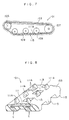
- a rubber crawler which is mounted on a motor vehicle such as an earth-moving vehicle, as shown in Fig. 7 and 8, presents an endless belt shape.
- the illustrated rubber crawler 101 is basically formed of a crawler body 103 that is made of rubber.
- the rubber crawler 101 is entrained around a drive roller 105 and an idler roller 107.
- a plurality of take-up rollers 109 is disposed at an inner peripheral side of the rubber crawler 101.
- a number of cores 111 are embedded in the crawler body 103 with predetermined spacing along a longitudinal direction of the rubber crawler.
- the cores 111 extend in a direction orthogonal to the rubber crawler longitudinal direction (i.e., a widthwise direction of the rubber crawler) and are disposed parallel with one another.
- a number of engagement holes 7 are formed in the crawler body and respectively disposed between two adjacent cores. Teeth of the drive roller (sprocket) engage with the engagement holes.
- Projections 111A of the cores 111 protrude from the rubber crawler inner peripheral surface.
- Cord layers are provided at posterior positions (at an outer peripheral side) on each side in the rubber crawler widthwise direction.
- Each cord layer is comprised of a plurality of steel cords C, each of which extends along the rubber crawler longitudinal direction and which are embedded parallel with one another.
- a plurality of lugs 115 are regularly provided at predetermined pitches in the rubber crawler longitudinal direction, each lug extending from the outer peripheral surface of the rubber crawler 101. All the lugs are integrally formed with crawler body 115.
- Such a conventional type rubber crawler generally has a shape or structure which is symmetrical in relation to the sprocket holes (a rubber crawler longitudinal center line).
- a rubber crawler which has an asymmetrical structure, has appeared. It is resulted from the fact that forming positions of sprocket holes are respectively shifted from widthwise direction center positions to one side due to an increase in crawler width based on the tendency of vehicles to become large.
- a thickness (rubber thickness) of a left side portion of a crawler body and a thickness (rubber thickness) of a right side portion of the crawler body are the same as in the conventional symmetrical type rubber crawler as described above.
- a body portion and lugs which are located at a shorter side, with regard to a length between a sprocket hole center and a side end face, of a crawler body, are damaged more easily than those located at a longer side of the crawler body.
- a rubber-made crawler body portion located at a weakened side might be unilaterally damaged or worn out. It is considered that this is because the areas of left and right portions of a rubber crawler, to which portions loads are applied when the rubber crawler is being used, are different from each other, and accordingly, the surface pressure differs between the left and right portions.
- One object of the invention is to provide an improved crawler having excellent durability and reliability or having a long life, in which a substantial difference in strength between one side in a widthwise direction (a left and right direction) of an asymmetrical type elastic endless crawler and the other side in the widthwise direction of the crawler can be eliminated or both of the sides of the crawler can have the same level of strength.
- an elastic endless crawler comprising an annular belt-shaped elastic crawler body characterized in that: the crawler body comprises a series of driven elements for operation of the crawler and a reference plane, which reference plane passes through respective centers of the drive elements and extends in a longitudinal direction of the crawler; and a thickness of one side relative to the reference plane and a thickness of the other side relative to the reference plane are different from one another.
- An illustrated rubber crawler 1 presents an endless belt form and includes a crawler body 3 that is made of rubber.
- a plurality of steel cores 5 are embedded in the crawler body 3 with predetermined intervals (or pitches) along a longitudinal direction of the rubber crawler.
- the cores 5 extend individually in a direction orthogonal to the rubber crawler longitudinal direction (i.e., a widthwise direction of the rubber crawler) and are disposed parallel with one another.
- Engagement holes 7 (or sprocket holes) are formed in the crawler body and respectively disposed between two adjacent cores.
- a plurality of lugs 11 are regularly provided in a protruding manner at an outer peripheral surface of the rubber crawler with predetermined intervals along the rubber crawler longitudinal direction.
- the lugs 11 are integrally formed with the crawler body 3.
- These lugs 11 can be divided by a reference plane A as a boundary into two groups of lugs 11: one group of lugs on the right side in Fig. 4 and the other group of lugs on the left side in the same figure.
- the lugs 11 of the right side lug group and the lugs 11 of the left side lug group are different from one another in size and shape and are disposed in an offset manner with respect to the rubber crawler longitudinal direction.
- the lugs 11 are generally disposed in a staggered manner. The intent of this disposition is to reduce generation of vibration or noise.
- the lugs 11 are not limited to the illustrated shapes and may have any appropriate shapes.
- a surface, which passes through each center of the engagement holes 7 and extends in the rubber crawler longitudinal direction, is defined as the reference plane A.
- Each of the cores 5 is arranged approximately in point symmetrical relation with respect to a center between the engagement holes 7 on both sides thereof and has two raised portions (bosses) 5a and 5b, which protrude from an inner peripheral surface of the rubber crawler, and wing portions 5c and 5d, which extend to respective sides, i.e., left (N ) side and right (W) side, respectively.
- Fitting portions i.e., a fitting concave portion 5e and a fitting convex portion 5f
- Fitting portions are provided one at each side of each of the cores 5, for an interconnection with adjacent cores.
- a dimension S W between the reference plane A and the end face of the right side wing portion 5d is greater than a dimension S N between the reference plane A and the end face of the left side wing portion 5c (S W > S N ).
- a dimension W W between the reference plane A and the right end of the crawler body is greater than a dimension W N between the reference plane A and the left end of the crawler body (W W > W N ).
- the left side wing portion 5c and the right side wing portion 5d of each of the cores 5 include tracker roller travelling portions (travelling surfaces) 5g of rectangular shape, which are exposed to the inner peripheral side of the rubber crawler and which are substantially coplanar with the inner peripheral surface of the rubber crawler.
- Grooves 13 are formed at the rubber crawler inner peripheral portion between each of two adjacent cores in order to reduce a winding resistance when the rubber crawler is being wound. Each groove 13 is formed until the vicinity of the tracker roller travelling portion 5g. However, it may be formed until the edge of the rubber crawler widthwise directional end.
- cord layers are formed and positioned behind or beneath the respective cores 5 (at the rubber crawler outer peripheral side), more specifically, behind or beneath the left side wing portions 5c and the right side wing portions 5d.
- Each of the cord layers includes a plurality of steel cords C, each of which extends along the rubber crawler longitudinal direction and which are embedded parallel with one another.
- a dimension H N between a cord center of one cord group and the rubber crawler inner peripheral surface and a dimension H W between a cord center of the other cord group and the rubber crawler inner peripheral surface are substantially the same (H N ⁇ H W ).
- a dimension T N between the cord center of the one cord group and the rubber crawler outer peripheral surface and a dimension T W between the cord center of the other cord group and the rubber crawler outer peripheral surface are different from each other (T N ⁇ T W , T N > T W , or (H N +T N ) ⁇ (H W + T W )).
- T N and T W which can be calculated from the above formula, should be determined such that a difference therebetween is approximately 2 to 15 mm. That is, in a case in which this difference is over 15 mm, a great difference in height between left and right lugs of a rubber crawler may exist, and therefore, this may have a deleterious effect on a driving force of a vehicle in which the rubber crawler is mounted. On the other hand, in a case in which the above difference is below 2 mm, there is a concern that it is not possible to accomplish the end desired.
- each lug has a hardness of approximately 70 degrees and an elongation of 400 % or more
- each body portion (rubber portion) on an inner peripheral side (tracker roller side) has a hardness of approximately 74 degrees and an elongation of 200 % or more.
- test vehicles in which respective rubber crawlers were mounted were prepared and driven under the following travelling conditions. Thereafter, the rubber crawlers were inspected for an external appearance.
- the experimental travelling conditions were such that each of the test vehicles was driven for 50 hours or through 5 cycles, wherein, in one cycle, the vehicle was driven for 8 hours on a rough road in a zigzag driving manner, for 1 hour on a metaled road in a zigzag driving manner, for fifteen minutes on a cobbled road in a figure-of-eight driving manner, and for forty-five minutes on a concrete road in a zigzag driving manner.
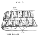
- Fig. 5 which is a copy of an external appearance of the example of the rubber crawler after the travelling, although wear has resulted in surfaces of lugs, it is not excessive, and there is almost no serious or major crack. Serious cracks did not occur in crawler body surface portions each between two adjacent lugs.
- Fig. 6 is a copy of an external appearance of the comparative example of the rubber crawler after the travelling.
- the shapes of the lugs have been substantially deformed and some lugs have been partly fractured. Further, there are portions where cord layers, which must have been embedded within the crawler body, are partly subjected outside.
- the number of occurrences of running off of the rubber crawler was zero, whereas the number of occurrences of running off of the rubber crawler (comparative example) was six.
Landscapes
- Engineering & Computer Science (AREA)
- Chemical & Material Sciences (AREA)
- Combustion & Propulsion (AREA)
- Transportation (AREA)
- Mechanical Engineering (AREA)
- Tires In General (AREA)
Abstract
Description
Claims (10)
- An elastic endless crawler comprising an annular belt-shaped elastic crawler body characterized in that:the crawler body (3) comprises a series of driven elements (7) for operation of the crawler and a reference plane (A), which reference plane passes through respective centers of the drive elements (7) and extends in a longitudinal direction of the crawler; anda thickness of one side relative to the reference plane (A) and a thickness of the other side relative to the reference plane are different from one another.
- The elastic endless crawler of claim 1, wherein lengths between respective crawler body end surfaces, said surfaces facing in a crawler widthwise direction, and the reference plane (A) are different from one another.
- The elastic endless crawler of claim 2, wherein a thickness of one side, which is shorter in length, of the crawler body (3) is greater than a thickness of the other side, which is longer in length, of the crawler body (3).
- The elastic endless crawler of claim 1, wherein a plurality of cords (C) for reinforcement are embedded at the respective sides or left and right sides relative to the reference plane (A) in the crawler body (3) such that the cords extend in the crawler longitudinal direction and are spaced apart along the crawler widthwise direction with a predetermined spacing.
- The elastic endless crawler of claim 4, wherein lengths between respective crawler end surfaces in a crawler widthwise direction and the reference plane (A) are different from one another and wherein when one side, which is shorter in length, is referred to as a N side and the other side, which is longer in length, is referred to as a W side and whena length dimension between a cord center at the N side and an outer peripheral surface of the crawler body (3) is TN,a length dimension between a cord center at the W side and the outer peripheral surface of the crawler body (3) is TW,a length dimension between the reference plane (A) and the N side crawler body end surface is WN, anda length dimension between the reference plane (A) and the W side crawler body end surface is WW,
- The elastic endless crawler of claim 4, wherein a plurality of cores (5) are embedded in the crawler body (3) with predetermined intervals along the crawler longitudinal direction such that the cores (5) extend individually in the crawler widthwise direction, which is orthogonal to the crawler longitudinal direction, and are disposed parallel with one another.
- The elastic endless crawler of claim 6, wherein the driven elements (7) comprise sprocket engaging holes (7), each of which is formed in the crawler body and disposed between two adjacent cores (5).
- The elastic endless crawler of claim 6, wherein lengths between respective crawler end surfaces in a crawler widthwise direction and the reference plane (A) are different from one another and wherein when one side, which is shorter in length, is referred to as a N side and the other side, which is longer in length, is referred to as a W side and whena length dimension between a cord center at the N side and an outer peripheral surface of the crawler body (3) is TN,a length dimension between a cord center at the W side and the outer peripheral surface of the crawler body (3) is TW,a length dimension between the reference plane (A) and a core end surface at the N side is SN, anda length dimension between the reference plane (A) and a core end surface at the W side is SW,
- The elastic endless crawler of claim 4, wherein a plurality of lugs (11) are regularly provided in a protruding manner at an outer peripheral surface of the crawler body (3) with predetermined intervals along the rubber crawler longitudinal direction.
- The elastic endless crawler of claim 9, wherein lengths between respective crawler end surfaces in a crawler widthwise direction and the reference plane (A) are different from one another and wherein when one side, which is shorter in length, is referred to as a N side and the other side, which is longer in length, is referred to as a W side and whena length dimension between a cord center at the N side and the outer peripheral surface of the crawler body (3) is TN,a length dimension between a cord center at the W side and the outer peripheral surface of the crawler body (3) is TW,a length dimension between the reference plane (A) and a lug edge at the N side is LN, anda length dimension between the reference plane (A) and a lug edge at the W side is LW,
Applications Claiming Priority (5)
| Application Number | Priority Date | Filing Date | Title |
|---|---|---|---|
| JP2001011644 | 2001-04-16 | ||
| JP2001116444 | 2001-04-16 | ||
| JP2001214299A JP4181314B2 (en) | 2001-04-16 | 2001-07-13 | Rubber crawler |
| JP2001214299 | 2001-07-13 | ||
| PCT/JP2002/003669 WO2002085692A1 (en) | 2001-04-16 | 2002-04-12 | Elastic endless crawler |
Publications (3)
| Publication Number | Publication Date |
|---|---|
| EP1386831A1 true EP1386831A1 (en) | 2004-02-04 |
| EP1386831A4 EP1386831A4 (en) | 2004-08-25 |
| EP1386831B1 EP1386831B1 (en) | 2010-11-10 |
Family
ID=26613620
Family Applications (1)
| Application Number | Title | Priority Date | Filing Date |
|---|---|---|---|
| EP02717126A Expired - Lifetime EP1386831B1 (en) | 2001-04-16 | 2002-04-12 | Elastic endless crawler |
Country Status (5)
| Country | Link |
|---|---|
| US (1) | US7044567B2 (en) |
| EP (1) | EP1386831B1 (en) |
| JP (1) | JP4181314B2 (en) |
| DE (1) | DE60238248D1 (en) |
| WO (1) | WO2002085692A1 (en) |
Cited By (1)
| Publication number | Priority date | Publication date | Assignee | Title |
|---|---|---|---|---|
| JP2016144982A (en) * | 2015-02-06 | 2016-08-12 | 株式会社クボタ | Elastic crawler |
Families Citing this family (33)
| Publication number | Priority date | Publication date | Assignee | Title |
|---|---|---|---|---|
| JP4272580B2 (en) * | 2003-12-04 | 2009-06-03 | ゼニス産業株式会社 | Elastic crawler |
| JP4849992B2 (en) * | 2006-05-16 | 2012-01-11 | 住友ゴム工業株式会社 | Rubber crawler |
| JP4896594B2 (en) * | 2006-06-05 | 2012-03-14 | 住友ゴム工業株式会社 | Rubber crawler |
| JP4758290B2 (en) * | 2006-06-20 | 2011-08-24 | 株式会社ブリヂストン | Crawler structure |
| WO2008106230A1 (en) * | 2007-02-28 | 2008-09-04 | Mclaren Group Holdings Pte. Ltd. | Offset track |
| JP4922017B2 (en) * | 2007-03-06 | 2012-04-25 | 株式会社ブリヂストン | Rubber crawler |
| WO2009105892A1 (en) * | 2008-02-28 | 2009-09-03 | Camoplast Inc. | Endless track for an off-road work vehicle to produce a net non-null lateral force |
| JP2009292204A (en) * | 2008-06-03 | 2009-12-17 | Bridgestone Corp | Rubber crawler |
| USD615106S1 (en) * | 2009-03-31 | 2010-05-04 | Bridgestone Corporation | Rubber crawler |
| USD618254S1 (en) * | 2009-03-31 | 2010-06-22 | Bridgestone Corporation | Rubber crawler |
| USD615105S1 (en) * | 2009-05-26 | 2010-05-04 | Bridgestone Corporation | Rubber crawler |
| USD618710S1 (en) * | 2009-05-26 | 2010-06-29 | Bridgestone Corporation | Rubber crawler |
| KR101146092B1 (en) | 2009-12-11 | 2012-05-15 | 한국카모플라스트(주) | Rubber crawler that component shock suction a groove |
| US8967737B2 (en) | 2010-06-30 | 2015-03-03 | Camoplast Solideal Inc. | Wheel of a track assembly of a tracked vehicle |
| US8985250B1 (en) | 2010-12-14 | 2015-03-24 | Camoplast Solideal Inc. | Track drive mode management system and methods |
| US9162718B2 (en) | 2010-12-14 | 2015-10-20 | Camso Inc. | Endless track for traction of a vehicle |
| US9334001B2 (en) | 2010-12-14 | 2016-05-10 | Camso Inc. | Drive sprocket, drive lug configuration and track drive arrangement for an endless track vehicle |
| JP2011116368A (en) * | 2011-03-14 | 2011-06-16 | Bridgestone Corp | Crawler structure |
| US20160016621A1 (en) | 2013-03-15 | 2016-01-21 | Camoplast Solideal Inc. | Endless track for traction of a vehicle |
| EP3265368B2 (en) | 2015-03-04 | 2024-07-24 | Camso Inc. | Track system for traction of a vehicle |
| US10953937B2 (en) | 2015-05-06 | 2021-03-23 | Camso Inc. | Track for traction of a vehicle |
| CA3042780C (en) | 2015-06-29 | 2022-06-21 | Camso Inc. | Systems and methods for monitoring a track system for traction of a vehicle |
| USD870594S1 (en) | 2016-06-28 | 2019-12-24 | Camso Inc. | Track for traction of a vehicle |
| AU2017328837A1 (en) * | 2016-09-14 | 2019-03-21 | Fukuyama Rubber Ind. Co., Ltd. | Elastic crawler and crawler-type travel device |
| US10589809B2 (en) * | 2016-11-01 | 2020-03-17 | Contitech Transportbandsysteme Gmbh | Urethane hybrid agricultural vehicle track |
| US10099734B2 (en) * | 2016-11-01 | 2018-10-16 | Contitech Transportbandsysteme Gmbh | Urethane hybrid agricultural vehicle track |
| US11738813B2 (en) | 2016-11-01 | 2023-08-29 | Loc Performance Products, Llc | Urethane hybrid agricultural vehicle track |
| RU2643310C1 (en) * | 2017-04-19 | 2018-01-31 | Акционерное Общество "Машиностроительная Компания "Витязь" | Caterpillar of vehicle |
| WO2019109191A1 (en) | 2017-12-08 | 2019-06-13 | Camso Inc. | Systems and methods for monitoring off-road vehicles |
| WO2020041897A1 (en) | 2018-08-30 | 2020-03-05 | Camso Inc. | Systems and methods for monitoring tracked vehicles |
| EP3844473B1 (en) | 2018-08-30 | 2026-06-10 | Camso Inc. | Systems and methods for monitoring vehicles with tires |
| US11970226B2 (en) * | 2019-11-18 | 2024-04-30 | Yong Jae Choi | Elastic crawler |
| CN115743334A (en) * | 2022-12-08 | 2023-03-07 | 清华大学苏州汽车研究院(吴江) | Tracked vehicle traveling system and tracked vehicle |
Family Cites Families (11)
| Publication number | Priority date | Publication date | Assignee | Title |
|---|---|---|---|---|
| JPS6043837B2 (en) | 1981-02-24 | 1985-09-30 | アマダ・エンジニアリング・アンド・サ−ビス・カンパニ−・インコ−ポレ−テツド | Laser processing equipment |
| JPS621026Y2 (en) * | 1981-02-27 | 1987-01-10 | ||
| JPS5885577U (en) * | 1981-12-04 | 1983-06-10 | オ−ツタイヤ株式会社 | Elastic tracks for crawlers |
| JPH08150969A (en) * | 1994-11-29 | 1996-06-11 | Ohtsu Tire & Rubber Co Ltd :The | Elastic crawler |
| JPH08188184A (en) * | 1995-01-13 | 1996-07-23 | Ohtsu Tire & Rubber Co Ltd :The | Elastic crawler and tire driven crawler traveling device |
| US6290009B1 (en) * | 1996-08-20 | 2001-09-18 | Yanmar Diesel Engine Co., Ltd. | Swivel working vehicle |
| JPH10250650A (en) * | 1997-03-17 | 1998-09-22 | Komatsu Zenoah Co | Track-type work vehicle and its rubber track |
| JPH11278325A (en) * | 1998-03-30 | 1999-10-12 | Bridgestone Corp | Eccentric rubber crawler |
| US6155657A (en) * | 1998-08-21 | 2000-12-05 | Aqua Products Inc. | Drive track for self-propelled pool cleaner |
| JP3658536B2 (en) * | 2000-06-23 | 2005-06-08 | 大陸化學工業株式會社 | Elastic crawler |
| US6520603B2 (en) * | 2001-03-15 | 2003-02-18 | Takeuchi Mfg, Co., Ltd. | Low-noise endless crawler belt having embedded core bars and detachable crawler shoes |
-
2001
- 2001-07-13 JP JP2001214299A patent/JP4181314B2/en not_active Expired - Fee Related
-
2002
- 2002-04-12 US US10/474,699 patent/US7044567B2/en not_active Expired - Fee Related
- 2002-04-12 DE DE60238248T patent/DE60238248D1/en not_active Expired - Lifetime
- 2002-04-12 EP EP02717126A patent/EP1386831B1/en not_active Expired - Lifetime
- 2002-04-12 WO PCT/JP2002/003669 patent/WO2002085692A1/en not_active Ceased
Cited By (1)
| Publication number | Priority date | Publication date | Assignee | Title |
|---|---|---|---|---|
| JP2016144982A (en) * | 2015-02-06 | 2016-08-12 | 株式会社クボタ | Elastic crawler |
Also Published As
| Publication number | Publication date |
|---|---|
| DE60238248D1 (en) | 2010-12-23 |
| JP4181314B2 (en) | 2008-11-12 |
| JP2003002264A (en) | 2003-01-08 |
| EP1386831B1 (en) | 2010-11-10 |
| US20040130212A1 (en) | 2004-07-08 |
| WO2002085692A1 (en) | 2002-10-31 |
| EP1386831A4 (en) | 2004-08-25 |
| US7044567B2 (en) | 2006-05-16 |
Similar Documents
| Publication | Publication Date | Title |
|---|---|---|
| US7044567B2 (en) | Elastic endless crawler | |
| EP0895924B1 (en) | Rubber crawler track | |
| US8191976B2 (en) | Coreless rubber crawler track | |
| US4904030A (en) | Rubber crawler | |
| EP2123544B1 (en) | Rubber track | |
| US6079802A (en) | Rubber crawler | |
| US20100096915A1 (en) | Rubber crawler track | |
| US10435091B2 (en) | Elastic crawler and elastic crawler device | |
| US7077485B2 (en) | Rubber crawler | |
| CN1669862A (en) | Rubber crawler belt | |
| CN102481961A (en) | Rubber crawler | |
| WO2003095292A1 (en) | Rubber crawler | |
| JP5319249B2 (en) | Elastic track | |
| JP4146001B2 (en) | Elastic crawler and widthwise reinforcement for elastic crawler | |
| JP4722313B2 (en) | Protrusion-driven rubber crawler | |
| CN110450872B (en) | Elastic crawler belt | |
| JP2724871B2 (en) | Infinite elastic orbit belt | |
| US10435090B2 (en) | Elastic crawler | |
| US8672423B2 (en) | Rubber track | |
| JP3179666B2 (en) | Crawler elastic track | |
| KR100725022B1 (en) | Elastic Crawler | |
| JP4151943B2 (en) | Elastic crawler | |
| JP2871192B2 (en) | Crawler core metal and elastic crawler | |
| KR200168511Y1 (en) | An orbit for a shock prevention | |
| JP3939409B2 (en) | Elastic crawler core |
Legal Events
| Date | Code | Title | Description |
|---|---|---|---|
| PUAI | Public reference made under article 153(3) epc to a published international application that has entered the european phase |
Free format text: ORIGINAL CODE: 0009012 |
|
| 17P | Request for examination filed |
Effective date: 20031028 |
|
| AK | Designated contracting states |
Kind code of ref document: A1 Designated state(s): AT BE CH CY DE DK ES FI FR GB GR IE IT LI LU MC NL PT SE TR |
|
| AX | Request for extension of the european patent |
Extension state: AL LT LV MK RO SI |
|
| A4 | Supplementary search report drawn up and despatched |
Effective date: 20040713 |
|
| 17Q | First examination report despatched |
Effective date: 20050228 |
|
| GRAP | Despatch of communication of intention to grant a patent |
Free format text: ORIGINAL CODE: EPIDOSNIGR1 |
|
| RTI1 | Title (correction) |
Free format text: ELASTIC ENDLESS CRAWLER FOR VEHICLE |
|
| RBV | Designated contracting states (corrected) |
Designated state(s): DE FR GB IT |
|
| GRAS | Grant fee paid |
Free format text: ORIGINAL CODE: EPIDOSNIGR3 |
|
| GRAA | (expected) grant |
Free format text: ORIGINAL CODE: 0009210 |
|
| RTI1 | Title (correction) |
Free format text: ELASTIC ENDLESS CRAWLER |
|
| AK | Designated contracting states |
Kind code of ref document: B1 Designated state(s): DE FR GB IT |
|
| REG | Reference to a national code |
Ref country code: GB Ref legal event code: FG4D |
|
| REF | Corresponds to: |
Ref document number: 60238248 Country of ref document: DE Date of ref document: 20101223 Kind code of ref document: P |
|
| PLBE | No opposition filed within time limit |
Free format text: ORIGINAL CODE: 0009261 |
|
| STAA | Information on the status of an ep patent application or granted ep patent |
Free format text: STATUS: NO OPPOSITION FILED WITHIN TIME LIMIT |
|
| 26N | No opposition filed |
Effective date: 20110811 |
|
| REG | Reference to a national code |
Ref country code: DE Ref legal event code: R097 Ref document number: 60238248 Country of ref document: DE Effective date: 20110811 |
|
| REG | Reference to a national code |
Ref country code: DE Ref legal event code: R082 Ref document number: 60238248 Country of ref document: DE Representative=s name: BARDEHLE PAGENBERG PARTNERSCHAFT MBB PATENTANW, DE |
|
| REG | Reference to a national code |
Ref country code: FR Ref legal event code: CA Effective date: 20140812 |
|
| REG | Reference to a national code |
Ref country code: DE Ref legal event code: R081 Ref document number: 60238248 Country of ref document: DE Owner name: BRIDGESTONE CORPORATION, JP Free format text: FORMER OWNER: BRIDGESTONE CORP., TOKIO/TOKYO, JP Effective date: 20140828 Ref country code: DE Ref legal event code: R082 Ref document number: 60238248 Country of ref document: DE Representative=s name: BARDEHLE PAGENBERG PARTNERSCHAFT MBB PATENTANW, DE Effective date: 20140828 |
|
| REG | Reference to a national code |
Ref country code: FR Ref legal event code: PLFP Year of fee payment: 15 |
|
| PGFP | Annual fee paid to national office [announced via postgrant information from national office to epo] |
Ref country code: GB Payment date: 20160421 Year of fee payment: 15 Ref country code: DE Payment date: 20160421 Year of fee payment: 15 |
|
| PGFP | Annual fee paid to national office [announced via postgrant information from national office to epo] |
Ref country code: IT Payment date: 20160427 Year of fee payment: 15 |
|
| REG | Reference to a national code |
Ref country code: FR Ref legal event code: PLFP Year of fee payment: 16 |
|
| REG | Reference to a national code |
Ref country code: DE Ref legal event code: R119 Ref document number: 60238248 Country of ref document: DE |
|
| GBPC | Gb: european patent ceased through non-payment of renewal fee |
Effective date: 20170412 |
|
| PG25 | Lapsed in a contracting state [announced via postgrant information from national office to epo] |
Ref country code: DE Free format text: LAPSE BECAUSE OF NON-PAYMENT OF DUE FEES Effective date: 20171103 |
|
| PG25 | Lapsed in a contracting state [announced via postgrant information from national office to epo] |
Ref country code: GB Free format text: LAPSE BECAUSE OF NON-PAYMENT OF DUE FEES Effective date: 20170412 |
|
| REG | Reference to a national code |
Ref country code: FR Ref legal event code: PLFP Year of fee payment: 17 |
|
| PG25 | Lapsed in a contracting state [announced via postgrant information from national office to epo] |
Ref country code: IT Free format text: LAPSE BECAUSE OF NON-PAYMENT OF DUE FEES Effective date: 20170412 |
|
| PGFP | Annual fee paid to national office [announced via postgrant information from national office to epo] |
Ref country code: FR Payment date: 20190418 Year of fee payment: 18 |
|
| PG25 | Lapsed in a contracting state [announced via postgrant information from national office to epo] |
Ref country code: FR Free format text: LAPSE BECAUSE OF NON-PAYMENT OF DUE FEES Effective date: 20200430 |