EP1386811A1 - Compressed air supply installation for compressed air systems of vehicles - Google Patents
Compressed air supply installation for compressed air systems of vehicles Download PDFInfo
- Publication number
- EP1386811A1 EP1386811A1 EP03016545A EP03016545A EP1386811A1 EP 1386811 A1 EP1386811 A1 EP 1386811A1 EP 03016545 A EP03016545 A EP 03016545A EP 03016545 A EP03016545 A EP 03016545A EP 1386811 A1 EP1386811 A1 EP 1386811A1
- Authority
- EP
- European Patent Office
- Prior art keywords
- compressed air
- valve
- air supply
- supply device
- pressure
- Prior art date
- Legal status (The legal status is an assumption and is not a legal conclusion. Google has not performed a legal analysis and makes no representation as to the accuracy of the status listed.)
- Granted
Links
Images

Classifications
-
- B—PERFORMING OPERATIONS; TRANSPORTING
- B60—VEHICLES IN GENERAL
- B60T—VEHICLE BRAKE CONTROL SYSTEMS OR PARTS THEREOF; BRAKE CONTROL SYSTEMS OR PARTS THEREOF, IN GENERAL; ARRANGEMENT OF BRAKING ELEMENTS ON VEHICLES IN GENERAL; PORTABLE DEVICES FOR PREVENTING UNWANTED MOVEMENT OF VEHICLES; VEHICLE MODIFICATIONS TO FACILITATE COOLING OF BRAKES
- B60T17/00—Component parts, details, or accessories of power brake systems not covered by groups B60T8/00, B60T13/00 or B60T15/00, or presenting other characteristic features
- B60T17/02—Arrangements of pumps or compressors, or control devices therefor
-
- B—PERFORMING OPERATIONS; TRANSPORTING
- B60—VEHICLES IN GENERAL
- B60T—VEHICLE BRAKE CONTROL SYSTEMS OR PARTS THEREOF; BRAKE CONTROL SYSTEMS OR PARTS THEREOF, IN GENERAL; ARRANGEMENT OF BRAKING ELEMENTS ON VEHICLES IN GENERAL; PORTABLE DEVICES FOR PREVENTING UNWANTED MOVEMENT OF VEHICLES; VEHICLE MODIFICATIONS TO FACILITATE COOLING OF BRAKES
- B60T11/00—Transmitting braking action from initiating means to ultimate brake actuator without power assistance or drive or where such assistance or drive is irrelevant
- B60T11/10—Transmitting braking action from initiating means to ultimate brake actuator without power assistance or drive or where such assistance or drive is irrelevant transmitting by fluid means, e.g. hydraulic
- B60T11/28—Valves specially adapted therefor
- B60T11/32—Automatic cut-off valves for defective pipes
- B60T11/326—Automatic cut-off valves for defective pipes in pneumatic systems
Definitions
- the invention relates to a compressed air supply device for vehicle compressed air systems comprising a multi-circuit protection valve, a pressure regulator, a supply line to supply the circuits of the multi-circuit protection valve with Compressed air, and a compressor, by means of a pneumatic Switching device is switchable.
- Such compressed air supply facilities are known.
- such a compressed air supply device from DE 100 04 091 A1 of the Applicant known.
- DE 100 04 001 A1 compressed air supply device for vehicle compressed air systems It is already possible with simple means an efficient Circuit of the compressors used in or for Compressed air supply equipment for vehicle compressed air systems to provide, with a small Frame size is feasible.
- a compressed air supply device comprising for vehicle compressed air systems a multi-circuit protection valve, a pressure regulator, a supply line to supply the circuits of the multi-circuit protection valve with compressed air, and a compressor that in particular by means of a pneumatic switching device is directly switchable, wherein between the switching device and the pressure regulator a quick exhaust valve is provided.
- Corresponding energy-saving compressors or energy-saving Switching compressors are, for example, from DE 39 09 531 A1 or DE 195 29 684 C2.
- At the energy-saving compressor according to DE 39 09 531 A1 is by a pressure regulator of Regulated piston compressor, with optimum power savings is desired.
- the suction valve in the idle phase is switched to an inactive position.
- the suction lamella of the suction valve by means a via a transmission lever acting on them actuating piston from the pumping position to the switch-off position or idle position on the underside of the valve carrier shifted, such that the suction openings of the reciprocating compressor at least partially open, so from the Suction lamella are not completely covered.
- From DE 195 29 684 C2 is also a corresponding piston compressor or energy-saving switching compressor or Energy-saving compressor known with one opposite one Valve carrier of the reciprocating compressor acting suction plate, which is to be used in a power saving system between one of the pumping phase corresponding position on the valve carrier and a position corresponding to the idling phase movable is, wherein in the idle phase, the pressure openings of Valve carrier are covered by the suction plate while the suction openings of the valve carrier partially exposed are, with the suction plate as one between valve carrier and compressor housing supported, by actuating means is formed rotatable disc relative to the valve carrier, the disc being one in the pumping phase opposite the Suction openings acting functional part and one with the Function part connected rest part exists.
- Such an energy-saving compressor is such that in the idle phase of the compressor, the suction lamella the delivery position is moved to the idle position. The outlet holes are closed, the suction holes are released and thus the suction chamber in the cylinder head switched to the compression room. A check valve in the suction chamber prevents the backflow of the sucked Air in the intake pipe. In this state works the compressor in a closed cycle - only Require friction, leakage and heat loss minimal drive energy. There is no compression in the compression room Pressure reversal more, thereby reducing the oil consumption.
- ESS Energy Saving System
- the displacement of the suction plate takes over the control piston, the integrated in the compressor switching device.
- the Switching device is controlled by the pressure regulator.
- the system pressure acts as a control pressure on the Control piston and moves him to the end position. This movement is via the drive pin and a lever transferred to the suction plate.
- a compression spring moves the control piston including Suction lamella back to the starting position.
- the switching device is a switching element or an actuator.
- Under control of the pressure regulator is in Under this invention, in particular the operation of a Drain or safety valve of the pressure regulator understood.
- the pilot valve is a solenoid valve. This measure is a simple driving or Switching the pilot valve possible.
- the pressure regulator comprises the pilot valve
- the pressure regulator comprises the pilot valve
- a control and / or regulating electronics provided, which controls the pilot valve and / or regulates. Further preferably, the supply line connects the pressure regulator with the multi-circuit protection valve.
- At least one pressure sensor is provided is an energy-saving operation of the switching compressor or the compressed air supply device in a simple way and way possible.
- connection line is preferably a ventilation hole and in particular preferably a central ventilation bore.
- the pressure regulator and the multi-circuit protection valve housed in a unit. This unit In particular, it may also preferably contain the compressor.
- the pressure regulator is electropneumatic.
- the multi-circuit protection valve is electropneumatic.
- the multi-circuit protection valve a four-circuit protection valve.
- At least one pressure sensor for measuring the Pressure is provided in the connecting line, a meaningful control or regulation of the compressor by means of only the at least one pressure sensor happen.
- a check valve in particular a check valve is provided is a safer Operation of the compressed air supply device possible.
- each circle of the Multi-circuit protection valve is measurable by means of pressure sensors, is beyond the regulation or control of the compressor too the supply of compressed air in the consumer circuits and the Removal of compressed air for the transfer of a circle in the other controllable or controllable.
- a fast one Switching is preferably realized in that the Nominal cross section of the pilot valve, in particular of the solenoid valve, is greater than the nominal cross section of the throttle. The larger the ratio of the respective nominal cross sections, the faster is a shift in particular the compressed air supply device possible.
- the throttle is inserted into the housing. Further preferably are chokes with different nominal cross sections respectively inserted.
- the compressor is an energy-saving compressor.
- a Pilot valve When a Pilot valve is provided that the pressure controls and the switching device controls, can be a pilot valve be saved and also corresponding holes to this pilot valve. By saving a pilot valve it is preferably possible the size corresponding Keep compressed air supply equipment small. Furthermore, higher switching speeds are due to achieve that the response time of the pilot valve that in Compared to, for example, DE 198 34 705 A1 is omitted, not more to take into account.
- a pilot valve switches namely at the same time the pressure regulator and the pneumatic Actuator via the quick exhaust valve.
- the quick exhaust valve as a shuttle valve, designed in particular with a preferred conveying direction.
- a compressed air system with a compressed air supply device provided the aforementioned type.
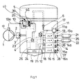
- Fig. 1 shows an embodiment of the invention a Compressed air supply device for vehicle compressed air systems.
- the compressed air supply device comprises a Air dryer 5 and a common housing 20.
- An energy-saving compressor 1 is a compressor line 2 with a Inlet 3 is attached to the common housing.
- In the common housing are also an electropneumatic Pressure regulator 4 and a four-circuit protection valve arranged.
- the coming of the four-circuit protection valve Air pressures are from the individual pressure control units or circles 13 to 16 via corresponding connection piece 13a to 16a to containers for the respective circles 21 and 22 headed. In Fig. 1, only two of the four containers shown.
- the funded by the energy saving compressor 1 compressed air is via a compressor line 2 to the inlet nozzle 3 of Compressed air supply device supplied.
- compressed air supply device in particular also a device that both a compressor 1, comprising the compressor line 2 and the inlet nozzle 3, as well as a the these components in a common Housing 20 includes and also a device at the compressor by means of a line to the housing is connectable.
- the electropneumatic pressure regulator 4 From the inlet nozzle 3 is compressed air the electropneumatic pressure regulator 4 and then by the Air dryer cartridge 5 out. Downstream is a check valve 6, starting from which a central supply bore 18 continues.
- the electromechanical Pressure control units 13 to 16 supplied with compressed air From the central Compressed air supply hole 18, the electromechanical Pressure control units 13 to 16 supplied with compressed air.
- the pressure control units are shared by the Control electronics 24 controlled and give the compressed air over the associated connection piece 11 a to 16 a to compressed air circuits of the vehicle and that according to adjustable and / or pre-programmable parameters.
- the quick exhaust valve comprises 40 for sealing a grooved ring 42 which in the schematic sectional view shown dark toned is.
- the actuator 1a, the shift compressor 1 and the Energy-saving compressors Due to the very fast ventilation can the actuator 1a, the shift compressor 1 and the Energy-saving compressors also switch very fast and efficiently, so that the transitional time or the switching time is very short is held so that the loads on the blade or the slats remain very low.
- this measure is in particular a long life of the switching compressors or the energy-saving compressors allows.
- the solenoid valve 23 is dimensioned so that at a Fraction of the line 10a before the throttle 39 is still a sufficient Back pressure arises or exists to the electromechanical To switch pressure regulator 4. Also through the absence of another pilot valve and thus the Absence of the response time of this pilot valve, the Control line 10a vented quickly. Through the vent the control line 10a is the pneumatic actuator 1a moved back to its original position and the compressor starts to promote quickly again.
Abstract
Description
Die Erfindung betrifft eine Druckluftversorgungseinrichtung für Fahrzeug-Druckluftanlagen umfassend ein Mehrkreisschutzventil, einen Druckregler, eine Versorgungsleitung zur Versorgung der Kreise des Mehrkreisschutzventils mit Druckluft, und einen Kompressor, der mittels einer pneumatischen Schaltvorrichtung schaltbar ist.The invention relates to a compressed air supply device for vehicle compressed air systems comprising a multi-circuit protection valve, a pressure regulator, a supply line to supply the circuits of the multi-circuit protection valve with Compressed air, and a compressor, by means of a pneumatic Switching device is switchable.
Derartige Druckluftversorgungseinrichtungen sind bekannt. Beispielsweise ist eine derartige Druckluftversorgungseinrichtung aus der DE 100 04 091 A1 der Anmelderin bekannt. Bei der aus der DE 100 04 001 A1 bekannten Druckluftversorgungseinrichtung für Fahrzeug-Druckluftanlagen ist es schon möglich mit einfachen Mitteln eine effiziente Schaltung der dort verwendeten Kompressoren in oder für Druckluftversorgungseinrichtungen für Fahrzeug-Druckluftanlagen zur Verfügung zu stellen, wobei eine geringe Baugröße realisierbar ist.Such compressed air supply facilities are known. For example, such a compressed air supply device from DE 100 04 091 A1 of the Applicant known. In the known from DE 100 04 001 A1 compressed air supply device for vehicle compressed air systems It is already possible with simple means an efficient Circuit of the compressors used in or for Compressed air supply equipment for vehicle compressed air systems to provide, with a small Frame size is feasible.
Bei der aus der DE 198 34 705.7 der Anmelderin bekannten Druckluftversorgungseinrichtung für Fahrzeug-Druckluftanlagen wird ein pneumatisches Stellglied, das einen Schaltkompressor schaltet über ein Vorsteuerventil gesteuert, das ausschließlich hierfür Verwendung findet. Der Druckregler wird hingegen von einem anderen Ventil, nämlich einem Magnetventil gesteuert. Das Vorsteuerventil, das das Stellglied des Schaltkompressors steuert, wird über eine Vorsteuerventilversorgungsleitung mit Druckluft versorgt und steuert das Stellglied über eine separate Steuerbohrung. Je nachdem, ob der Schaltkompressor fördern soll oder nicht, wird die Steuerleitung belüftet oder entlüftet.In the known from DE 198 34 705.7 of the applicant Compressed air supply device for vehicle compressed air systems is a pneumatic actuator, the one Switching compressor controlled via a pilot valve, which is used exclusively for this purpose. Of the Pressure regulator is, however, from another valve, namely controlled by a solenoid valve. The pilot valve that the Actuator of the switching compressor controls is via a Pilot valve supply line supplied with compressed air and controls the actuator via a separate control bore. Depending on whether the switching compressor should promote or not, the control line is vented or vented.
Es ist Aufgabe der vorliegenden Erfindung, mit einfachen Mitteln ein effizientes Schalten von Kompressoren in oder für Druckluftversorgungseinrichtungen für Fahrzeug-Druckluftanlagen zu ermöglichen, wobei die Standzeit der Kompressoren möglichst lang sein soll. Es ist ferner Aufgabe der vorliegenden Erfindung, die Kosten für entsprechende Druckluftversorgungseinrichtungen möglichst gering zu halten.It is an object of the present invention, with simple Means efficient switching of compressors in or for compressed air supply equipment for vehicle compressed air systems allow the life of the Compressors should be as long as possible. It is also a task of the present invention, the cost of corresponding Keep compressed air supply facilities as low as possible.
Gelöst wird diese Aufgabe durch eine Druckluftversorgungseinrichtung für Fahrzeug-Druckluftanlagen umfassend ein Mehrkreisschutzventil, einen Druckregler, eine Versorgungsleitung zur Versorgung der Kreise des Mehrkreisschutzventils mit Druckluft, und einen Kompressor, der mittels einer pneumatischen Schaltvorrichtung ins- besondere unmittelbar schaltbar ist, wobei zwischen der Schaltvorrichtung und dem Druckregler ein Schnellentlüftungsventil vorgesehen ist.This problem is solved by a compressed air supply device comprising for vehicle compressed air systems a multi-circuit protection valve, a pressure regulator, a supply line to supply the circuits of the multi-circuit protection valve with compressed air, and a compressor that in particular by means of a pneumatic switching device is directly switchable, wherein between the switching device and the pressure regulator a quick exhaust valve is provided.
Durch diese erfindungsgemäße Lösung ist ein effizientes Schalten des Kompressors möglich, wobei insbesondere ein Schaltkompressor bzw. Energiesparkompressor sehr effizient und schnell geschaltet werden kann, so daß die Lebensdauer und damit die Standzeit derartiger Kompressoren deutlich erhöht werden kann.By this solution according to the invention is an efficient Switching the compressor possible, in particular a Switch compressor or energy-saving compressor very efficient and can be switched quickly, so that the life and thus the service life of such compressors clearly can be increased.
Entsprechende Energiesparkompressoren bzw. energiesparende Schaltkompressoren sind bspw. aus der DE 39 09 531 A1 oder der DE 195 29 684 C2 bekannt. Bei dem Energiesparkompressor gemäß der DE 39 09 531 A1 wird durch einen Druckregler der Kolbenverdichter geregelt, wobei eine optimale Leistungseinsparung erwünscht ist. Hierbei wird das Saugventil in der Leerlaufphase in eine inaktive Position geschaltet. Zu diesem Zweck wird die Sauglamelle des Saugventils mittels eines über einen Übersetzungshebel auf sie einwirkenden Betätigungskolbens aus der Pumpstellung in die Abschaltstellung bzw. Leerlaufstellung an der Unterseite des Ventilträgers verschoben, derart, daß die Saugöffnungen des Kolbenverdichters wenigstens teilweise geöffnet, also von der Sauglamelle nicht vollständig überdeckt, sind. Des weiteren überdeckt die Sauglamelle in der Leerlaufphase wenigstens teilweise die Drucköffnungen des Druckventils des Kolbenverdichters, um in der Leerlaufphase ein weiteres Fördern in Richtung des Verbrauchers zu verhindern. Außerdem ist innerhalb des Zylinderkopfes zwischen dem Sauganschluß des Kolbenverdichters und der das Saugventil und das Druckventil tragenden Ventilträgerplatte des Kolbenverdichters ein Rückschlagventil, vorzugsweise in Form eines Rückschlag-Lamellenventils, angeordnet, welches in Richtung des Saugraums öffnet und in Richtung der an den Sauganschluß angeschlossenen Saugleitung sperrt.Corresponding energy-saving compressors or energy-saving Switching compressors are, for example, from DE 39 09 531 A1 or DE 195 29 684 C2. At the energy-saving compressor according to DE 39 09 531 A1 is by a pressure regulator of Regulated piston compressor, with optimum power savings is desired. Here, the suction valve in the idle phase is switched to an inactive position. To For this purpose, the suction lamella of the suction valve by means a via a transmission lever acting on them actuating piston from the pumping position to the switch-off position or idle position on the underside of the valve carrier shifted, such that the suction openings of the reciprocating compressor at least partially open, so from the Suction lamella are not completely covered. Furthermore at least covers the suction lamella in the idling phase partly the pressure openings of the pressure valve of the reciprocating compressor, in the idle phase further conveying in the direction of the consumer. Besides that is within the cylinder head between the suction port of the Piston compressor and the suction valve and the pressure valve carrying the valve carrier plate of the reciprocating compressor Check valve, preferably in the form of a check valve, arranged, which in the direction of the suction chamber opens and in the direction of the connected to the suction port Suction line locks.
Bei der Abschalt- bzw. Leerlaufphase dieses Energiesparkompressors bzw. Kolbenverdichters werden die Drucköffnungen des Kompressors wenigstens teilweise geschlossen, so daß kein unnötiges Abblasen von Luft geschieht. Als Folge hiervon ist es nur erforderlich, ein den Leckageverlusten entsprechendes geringes Volumen über das im Zylinderkopf befindliche Rückschlagventil anzusaugen, wenn der Kolben des Verdichters in Leerlaufstellung der Sauglamelle eine Saugbewegung vollzieht. Bei vollständig geschlossenen Drucköffnungen des Verdichters reduziert sich die zusätzlich anzusaugende Luftmenge aus der Saugleitung auf das tatsächlich existierende Leervolumen im Zylinder bzw. im Verdichtungsraum. During the shutdown or idle phase of this energy-saving compressor or piston compressor are the pressure openings the compressor is at least partially closed, so that no unnecessary blowing off of air happens. As a result this only requires the leakage losses corresponding low volume over that in the cylinder head suction check valve when the piston the compressor in neutral position of the suction plate a Suction movement takes place. When fully closed Pressure openings of the compressor is reduced in addition amount of air to be sucked from the suction line to the actually existing void volume in the cylinder or in Compression chamber.
Aus der DE 195 29 684 C2 ist auch ein entsprechender Kolbenverdichter
bzw. energiesparender Schaltkompressor bzw.
Energiesparkompressor bekannt, der mit einer gegenüber einem
Ventilträger des Kolbenverdichters wirkenden Sauglamelle,
die zur Verwendung in einem Energiesparsystem zwischen
einer der Pumpphase entsprechenden Position am Ventilträger
und einer der Leerlaufphase entsprechenden Position bewegbar
ist, wobei in der Leerlaufphase die Drucköffnungen des
Ventilträgers durch die Sauglamelle abgedeckt sind, während
die Saugöffnungen des Ventilträgers teilweise freigelegt
sind, wobei die Sauglamelle als eine zwischen Ventilträger
und Verdichtergehäuse gehalterte, durch Betätigungsmittel
relativ zum Ventilträger drehbare Scheibe ausgebildet ist,
wobei die Scheibe aus einem in der Pumphase gegenüber den
Saugöffnungen wirkenden Funktionsteil und einem mit dem
Funktionsteil verbundenen Ruheteil besteht. Im Ruheteil befinden
sich hierbei Drucköffnungen, die in der Pumphase mit
den Drucköffnungen des Ventilträgers fluchten. Es sind ferner
zu beiden Seiten des Funktionsteils im Material des Ruheteils
Aussparungen vorgesehen, die nach Drehung der Sauglamelle
in die der Leerlaufphase entsprechenden Position
einen Teilbereich der Saugöffnungen des Ventilträgers überlappend
freilegen, während die im Ruheteil vorgesehenen
Drucköffnungen nach Drehung der Sauglamelle gegenüber den
Drucköffnungen des Ventilträgers seitlich versetzt sind,
derart, daß die Drucköffnungen des Ventilträgers in der
Leerlaufphase abgedeckt sind. Der Gegenstand der DE 195 29
684 C2 und der Gegenstand der DE 39 09 531 A1 soll durch
Inbezugnahme vollumfänglich in diese Anmeldung aufgenommen
sein.From DE 195 29 684 C2 is also a corresponding piston compressor
or energy-saving switching compressor or
Energy-saving compressor known with one opposite one
Valve carrier of the reciprocating compressor acting suction plate,
which is to be used in a power saving system between
one of the pumping phase corresponding position on the valve carrier
and a position corresponding to the idling phase movable
is, wherein in the idle phase, the pressure openings of
Valve carrier are covered by the suction plate while
the suction openings of the valve carrier partially exposed
are, with the suction plate as one between valve carrier
and compressor housing supported, by actuating means
is formed rotatable disc relative to the valve carrier,
the disc being one in the pumping phase opposite the
Suction openings acting functional part and one with the
Function part connected rest part exists. In the rest section
this pressure openings, in the pumping phase with
The pressure openings of the valve carrier are aligned. They are further
on both sides of the functional part in the material of the rest part
Recesses provided after rotation of the suction lamella
in the idling phase corresponding position
overlapping a portion of the suction openings of the valve carrier
uncover while the resting part provided
Pressure openings after rotation of the suction plate against the
Pressure openings of the valve carrier are laterally offset,
such that the pressure openings of the valve carrier in the
Idle phase are covered. The subject matter of DE 195 29
684 C2 and the subject of
Von der Anmelderin wird bei entsprechenden Druckluftversorgungseinrichtungen auch ein entsprechender Energiesparkompressor verwendet, beziehungsweise Kompressoren mit Energie-Spar-System (ESS) eingesetzt. Die Wirkungsweise eines derartigen Energiesparkompressors ist dergestalt, daß in der Leerlaufphase des Kompressors die Sauglamelle aus der Förderstellung in die Leerlaufstellung verschoben wird. Dabei werden die Auslaßbohrungen geschlossen, die Ansaugbohrungen werden freigegeben und damit der Saugraum im Zylinderkopf dem Kompressionsraum zugeschaltet. Ein Rückschlagventil im Saugraum verhindert das Rückströmen der angesaugten Luft in das Ansaugrohr. In diesem Zustand arbeitet der Kompressor in einem geschlossenen Kreisprozeß - lediglich Reibung, Leckströmung und Wärmeverlust erfordern minimale Antriebsenergie. Im Kompressionsraum erfolgt keine Druckumkehr mehr, dadurch sinkt der Ölverbrauch.By the applicant is at appropriate compressed air supply facilities also a corresponding energy-saving compressor used, or compressors used with Energy Saving System (ESS). The mode of action Such an energy-saving compressor is such that in the idle phase of the compressor, the suction lamella the delivery position is moved to the idle position. The outlet holes are closed, the suction holes are released and thus the suction chamber in the cylinder head switched to the compression room. A check valve in the suction chamber prevents the backflow of the sucked Air in the intake pipe. In this state works the compressor in a closed cycle - only Require friction, leakage and heat loss minimal drive energy. There is no compression in the compression room Pressure reversal more, thereby reducing the oil consumption.
Das Verschieben der Sauglamelle übernimmt der Schaltkolben, der im Kompressor integrierten Schalteinrichtung. Die Schalteinrichtung wird vom Druckregler gesteuert. In der Leerlaufphase wirkt der Systemdruck als Steuerdruck auf den Schaltkolben und verschiebt ihn bis in die Endstellung. Diese Bewegung wird über den Mitnehmerstift und einen Hebel auf die Sauglamelle übertragen. Sobald der Druckregler wieder auf Fördern umschaltet und dabei die Steuerleitung entlüftet, bewegt eine Druckfeder den Schaltkolben einschließlich Sauglamelle in die Ausgangslage zurück.The displacement of the suction plate takes over the control piston, the integrated in the compressor switching device. The Switching device is controlled by the pressure regulator. In the Idle phase, the system pressure acts as a control pressure on the Control piston and moves him to the end position. This movement is via the drive pin and a lever transferred to the suction plate. Once the pressure regulator again switches to conveying and thereby vents the control line, a compression spring moves the control piston including Suction lamella back to the starting position.
Bei den vorbeschriebenen Schaltkompressoren bzw. Energiesparkompressoren ist es notwendig, daß die Lamelle, die vom Stellglied geschaltet wird bzw. verschoben wird, beim Entlüften des Stellgliedes schnell verschoben werden, um eine Beschädigung der Lamelle zu verhindern. Eine Beschädigung der Lamelle kann dann geschehen, wenn das Schalten eine zu große Zeit in Anspruch nimmt, so daß bspw. beim Schalten in die Förderphase die Schubbewegung der Lamelle, die mit Schließvorgängen überlagert ist, zu einer hohen Belastung der Lamelle führt. Aus diesem Grunde ist eine sehr effiziente Schaltung erwünscht. Eine derartige effiziente und sehr schnelle Schaltung ist mittels der Erfindung möglich.In the above-described compressors or energy-saving compressors it is necessary that the lamella, the is switched by the actuator or is moved when Vent the actuator quickly to be moved to prevent damage to the slat. A damage The lamella can then happen when switching one takes too much time, so that, for example. When Switch into the conveying phase the pushing movement of the lamella, which is superimposed with closing operations, to a high load the slat leads. That's why a lot efficient circuit desired. Such an efficient and very fast switching is possible by means of the invention.
Vorzugsweise ist die Schaltvorrichtung ein Schaltglied oder ein Stellglied. Unter Steuerung des Druckreglers wird im Rahmen dieser Erfindung insbesondere die Betätigung eines Ablaß- oder Sicherheitsventils des Druckreglers verstanden. Preferably, the switching device is a switching element or an actuator. Under control of the pressure regulator is in Under this invention, in particular the operation of a Drain or safety valve of the pressure regulator understood.
Vorzugsweise ist das Vorsteuerventil ein Magnetventil. Durch diese Maßnahme ist ein einfaches Ansteuern bzw. Schalten des Vorsteuerventils möglich.Preferably, the pilot valve is a solenoid valve. This measure is a simple driving or Switching the pilot valve possible.
Wenn vorzugsweise der Druckregler das Vorsteuerventil umfaßt, ist eine sehr kompakte Bauform möglich.Preferably, when the pressure regulator comprises the pilot valve, is a very compact design possible.
Ferner vorzugsweise ist eine Steuer- und/oder Regelelektronik vorgesehen, die das Vorsteuerventil steuert und/oder regelt. Ferner vorzugsweise verbindet die Versorgungsleitung den Druckregler mit dem Mehrkreisschutzventil.Further preferably, a control and / or regulating electronics provided, which controls the pilot valve and / or regulates. Further preferably, the supply line connects the pressure regulator with the multi-circuit protection valve.
Wenn vorzugsweise wenigstens ein Drucksensor vorgesehen ist, ist ein energiesparender Betrieb des Schaltkompressors bzw. der Druckluftversorgungseinrichtung auf einfach Art und Weise möglich.If preferably at least one pressure sensor is provided is an energy-saving operation of the switching compressor or the compressed air supply device in a simple way and way possible.
Vorzugsweise ist wenigstens ein Drucksensor zum Messen des Drucks in der Verbindungsleitung vorgesehen. Die Verbindungsleitung ist vorzugsweise eine Belüftungsbohrung und insbesondere vorzugsweise eine zentrale Belüftungsbohrung. Vorzugsweise sind der Druckregler und das Mehrkreisschutzventil in einer Baueinheit untergebracht. Diese Baueinheit kann insbesondere vorzugsweise auch den Kompressor enthalten. Vorzugsweise ist der Druckregler elektropneumatisch. Vorzugsweise ist das Mehrkreisschutzventil elektropneumatisch. Ferner vorzugsweise ist das Mehrkreisschutzventil ein Vierkreisschutzventil.Preferably, at least one pressure sensor for measuring the Provided pressure in the connecting line. The connection line is preferably a ventilation hole and in particular preferably a central ventilation bore. Preferably, the pressure regulator and the multi-circuit protection valve housed in a unit. This unit In particular, it may also preferably contain the compressor. Preferably, the pressure regulator is electropneumatic. Preferably, the multi-circuit protection valve is electropneumatic. Further preferably, the multi-circuit protection valve a four-circuit protection valve.
Wenn vorzugsweise wenigstens ein Drucksensor zum Messen des Drucks in der Verbindungsleitung vorgesehen ist, kann eine sinnvolle Steuerung oder Regelung des Kompressors mittels nur des wenigstens einen Drucksensors geschehen.If preferably at least one pressure sensor for measuring the Pressure is provided in the connecting line, a meaningful control or regulation of the compressor by means of only the at least one pressure sensor happen.
Wenn vorzugsweise zwischen dem Druckregler und der Verbindungsleitung und insbesondere dem Drucksensor zum Messen des Drucks in der Verbindungsleitung ein Sperrventil, insbesondere ein Rückschlagventil, vorgesehen ist, ist ein sicherer Betrieb der Druckluftversorgungseinrichtung möglich. If preferably between the pressure regulator and the connecting line and in particular, the pressure sensor for measuring the pressure in the connecting line a check valve, in particular a check valve is provided is a safer Operation of the compressed air supply device possible.
Wenn vorzugsweise Druck in oder hinter jedem Kreis des Mehrkreisschutzventils mittels Drucksensoren meßbar ist, ist außer der Regelung oder Steuerung des Kompressors auch die Zufuhr von Druckluft in die Verbraucherkreise und die Entnahme von Druckluft zur Überleitung von einem Kreis in den anderen steuerbar oder regelbar.If preferably pressure in or behind each circle of the Multi-circuit protection valve is measurable by means of pressure sensors, is beyond the regulation or control of the compressor too the supply of compressed air in the consumer circuits and the Removal of compressed air for the transfer of a circle in the other controllable or controllable.
Wenn vorzugsweise zwischen dem Vorsteuerventil und dem Schaltglied eine Drossel vorgesehen ist, kann bei einem Bruch der Leitung zum Stellglied ein noch ausreichender Staudruck in der Druckluftversorgungseinrichtung vorherrschen, um den Druckregler zu schalten. Ein schnelles Schalten wird vorzugsweise dadurch realisiert, daß der Nennquerschnitt des Vorsteuerventils, insbesondere des Magnetventils, größer ist, als der Nennquerschnitt der Drossel. Je größer das Verhältnis der jeweiligen Nennquerschnitte, um so schneller ist ein Schalten insbesondere der Druckluftversorgungseinrichtung möglich. Vorzugsweise ist die Drossel in das Gehäuse einsteckbar. Ferner vorzugsweise sind Drosseln mit verschiedenen Nennquerschnitten jeweils einsteckbar.If preferably between the pilot valve and the Switching member is provided with a throttle, at a Breakage of the line to the actuator even more adequate Back pressure prevail in the compressed air supply device, to switch the pressure regulator. A fast one Switching is preferably realized in that the Nominal cross section of the pilot valve, in particular of the solenoid valve, is greater than the nominal cross section of the throttle. The larger the ratio of the respective nominal cross sections, the faster is a shift in particular the compressed air supply device possible. Preferably the throttle is inserted into the housing. Further preferably are chokes with different nominal cross sections respectively inserted.
In einer besonders bevorzugten Ausführungsform der Erfindung ist der Kompressor ein Energiesparkompressor. Wenn ein Vorsteuerventil vorgesehen ist, daß den Druck regler und die Schaltvorrichtung steuert, kann ein Vorsteuerventil eingespart werden und ferner entsprechende Bohrungen zu diesem Vorsteuerventil. Durch Einsparung eines Vorsteuerventils ist es vorzugsweise möglich die Baugröße entsprechender Druckluftversorgungseinrichtungen klein zu halten. Ferner sind höhere Schaltgeschwindigkeiten dadurch zu erzielen, daß die Ansprechzeit des Vorsteuerventils, daß im Vergleich zur bspw. DE 198 34 705 A1 wegfällt, nicht mehr zu berücksichtigen ist. Vorzugsweise schaltet ein Vorsteuerventil nämlich zugleich den Druckregler und das pneumatische Stellglied über das Schnellentlüftungsventil. In a particularly preferred embodiment of the invention the compressor is an energy-saving compressor. When a Pilot valve is provided that the pressure controls and the switching device controls, can be a pilot valve be saved and also corresponding holes to this pilot valve. By saving a pilot valve it is preferably possible the size corresponding Keep compressed air supply equipment small. Furthermore, higher switching speeds are due to achieve that the response time of the pilot valve that in Compared to, for example, DE 198 34 705 A1 is omitted, not more to take into account. Preferably, a pilot valve switches namely at the same time the pressure regulator and the pneumatic Actuator via the quick exhaust valve.
In einer besonders bevorzugten Ausführungsform der Erfindung ist das Schnellentlüftungsventil als Wechselventil, insbesondere mit bevorzugter Förderrichtung ausgestaltet.In a particularly preferred embodiment of the invention is the quick exhaust valve as a shuttle valve, designed in particular with a preferred conveying direction.
Erfindungsgemäß ist eine Druckluftanlage mit einer Druckluftversorgungseinrichtung der vorgenannten Art versehen.According to the invention, a compressed air system with a compressed air supply device provided the aforementioned type.
Die Erfindung wird nachstehend ohne Beschränkung des allgemeinen Erfindungsgedankens anhand von Ausführungsbeispielen unter Bezugnahme auf die Zeichnungen exemplarisch beschrieben, auf die im übrigen bezüglich der Offenbarung aller im Text nicht näher erläuterten erfindungsgemäßen Einzelheiten ausdrücklich verwiesen wird. Es zeigten:
- Fig. 1
- eine erfindungsgemäße Ausführungsform in schematischer Darstellung, und
- Fig. 2
- eine weitere Ausführungsform der Erfindung in schematischer Darstellung.
- Fig. 1
- an embodiment of the invention in a schematic representation, and
- Fig. 2
- a further embodiment of the invention in a schematic representation.
Fig. 1 zeigt eine erfindungsgemäße Ausführungsform einer
Druckluftversorgungseinrichtung für Fahrzeug-Druckluftanlagen.
Die Druckluftversorgungseinrichtung umfaßt einen
Lufttrockner 5 und ein gemeinsames Gehäuse 20. Ein Energiesparkompressor
1 ist über eine Kompressorleitung 2 mit einem
Eingangsstutzen 3 an dem gemeinsamen Gehäuse angebracht.
In dem gemeinsamen Gehäuse sind ferner ein elektropneumatischer
Druckregler 4 und ein Vierkreisschutzventil
angeordnet. Die von dem Vierkreisschutzventil gelangenden
Luftdrücke werden von den einzelnen Drucksteuereinheiten
bzw. Kreisen 13 bis 16 über entsprechende Anschlußstutzen
13a bis 16a zu Behältern für die jeweiligen Kreise 21 und
22 geleitet. In der Fig. 1 sind lediglich zwei der vier Behälter
dargestellt.Fig. 1 shows an embodiment of the invention a
Compressed air supply device for vehicle compressed air systems.
The compressed air supply device comprises a
Die vom Energiesparkompressor 1 geförderte Druckluft wird
über eine Kompressorleitung 2 zum Eingangsstutzen 3 der
Druckluftversorgungseinrichtung zugeführt. Im Rahmen dieser
Erfindung bedeutet Druckluftversorgungseinrichtung insbesondere
auch eine Einrichtung, die sowohl einen Kompressor
1, die Kompressorleitung 2 und den Eingangsstutzen 3 umfaßt,
als auch eine die diese Komponenten in einem gemeinsamen
Gehäuse 20 beinhaltet und auch eine Einrichtung, bei
der der Kompressor mittels einer Leitung mit dem Gehäuse
verbindbar ist. Von dem Eingangsstutzen 3 wird Druckluft
dem elektropneumatischen Druckregler 4 und danach durch die
Lufttrocknerpatrone 5 geführt. Nachgeordnet ist ein Rückschlagventil
6, von dem ausgehend eine zentrale Versorgungsbohrung
18 weitergeführt wird. Von der zentralen
Druckluftversorgungsbohrung 18 werden die elektromechanischen
Drucksteuereinheiten 13 bis 16 mit Druckluft versorgt.
Die Drucksteuereinheiten werden von der gemeinsamen
Steuerelektronik 24 angesteuert und geben die Druckluft über
die zugehörigen Anschlußstutzen 11a bis 16a an Druckluftkreise
des Fahrzeugs ab und zwar gemäß einstellbaren
und/oder vorprogrammierbaren Parametern.The funded by the
Erreicht der Druck, der durch den Drucksensor 12 hinter dem
Rückschlagventil 6 gemessen wird, den oberen Schwellwert,
so schaltet die gemeinsame Steuerelektronik 24 die Signalleitung
26 derart, daß die pneumatische Steuerleitung 10a
über den Anschluß 10 belüftet wird, wodurch das pneumatische
Stellglied 1a umschaltet und der Kompressor zu fördern
aufhört. Dieses geschieht mittels Steuerung oder Regelung
eines Schnellentlüftungsventils 40, daß mit einem Magnetventil
23 verbunden ist, das auch zur Steuerung oder Regelung
des Druckreglers 4 vorgesehen ist. Bei der Steuerung
oder Regelung des Druckreglers 4 wird insbesondere ein
Ablaß- oder Sicherheitsventil mittels des Magnetventils 23
betätigt. Der Meßwert des gemessenen Drucks wird über die
elektrische Verbindung 25 zur Steuerelektronik 24 geleitet.Reaches the pressure by the
Bei der Belüftung der Steuerleitung 10a gelangt Druckluft
von dem Magnetventil 23 über eine Drossel 39 über den Eingang
des Schnellentlüftungsventils und den mit kleinem
Querschnitt versehenen Ausgang des Schnellentlüftungsventils
zur Steuerleitung 10a. Der Weg der Belüftung
bzw. der Druckluft bei der Belüftung entspricht in der
Fig. 2 der nicht bevorzugten Stellung des Wechselventils
41. Wie in Fig. 1 dargestellt ist, umfaßt das Schnellentlüftungsventil
40 zur Abdichtung einen Nutring 42, der in
der schematischen Schnittdarstellung dunkel straffiert dargestellt
ist.During the ventilation of the
Fällt der Druck in der Leitung 18 hinter dem Rückschlagventil
6 durch beispielsweise Luftentnahme wie beispielsweise
beim Abbremsen des Fahrzeuges unter einen unteren
Schwellwert, so wird durch die gemeinsame Steuerelektronik
24 über die Signalleitung 26 ein Invertieren des Magnetventils
23 hervorgerufen, wodurch das Schnellentlüftungsventil
40 gemäß Fig. 1 bzw. das Wechselventil 41 gemäß
Fig. 2 in die Position überführt wird, die zu einer schnellen
Entlüftung der Steuerleitung 10a führt. In dieser Position
ist ein wesentlich größerer Querschnitt für die Druckluft
zur Entlüftung vorgesehen, so daß eine sehr schnelle
Entlüftung möglich ist. Durch die sehr schnelle Entlüftung
kann das Stellglied 1a den Schaltkompressor 1 bzw. den Energiesparkompressor
auch sehr schnell und effizient schalten,
so daß die Übergangszeit bzw. die Schaltzeit sehr kurz
gehalten wird, so daß die Belastungen an der Lamelle bzw.
den Lamellen sehr gering bleiben. Durch diese Maßnahme ist
insbesondere eine lange Lebensdauer der Schaltkompressoren
bzw. der Energiesparkompressoren ermöglicht.If the pressure in the
Das Magnetventil 23 ist so dimensioniert, daß bei einem
Bruch der Leitung 10a vor der Drossel 39 noch ein hinreichender
Staudruck entsteht bzw. vorhanden ist, um den elektromechanischen
Druckregler 4 zu schalten. Auch durch
das Fehlen eines weiteren Vorsteuerventils und damit das
Fehlen der Ansprechzeit dieses Vorsteuerventils, wird die
Steuerleitung 10a schnell entlüftet. Durch die Entlüftung
der Steuerleitung 10a wird das pneumatische Stellglied 1a
wieder in seine Ausgangslage bewegt und der Kompressor beginnt
schnell wieder zu fördern. The
- 11
- EnergiesparkompressorEnergy-saving compressor
- 1a1a
- pneumatisches Stellgliedpneumatic actuator
- 22
- Kompressorleitungcompressor line
- 33
- Eingangsstutzeninlet connection
- 44
- elektropneumatischer Druckreglerelectropneumatic pressure regulator
- 55
- LufttrocknerpatroneAir dryer cartridge
- 66
- Rückschlagventilcheck valve
- 1010
- AnschlußConnection
- 10a10a
- pneumatische Steuerleitungpneumatic control line
- 1111
- Überströmventil für LuftfederungOverflow valve for air suspension
- 11a11a
- Anschlußstutzen für LuftfederungConnecting piece for air suspension
- 1212
- Drucksensorpressure sensor
- 1313
-
elektromechanische Drucksteuereinheit für Kreis 1electromechanical pressure control unit for
circuit 1 - 13a13a
- Anschlußstutzen für 13Connecting piece for 13
- 1414
-
elektromechanische Drucksteuereinheit für Kreis 2electromechanical pressure control unit for
circuit 2 - 14a14a
- Anschlußstutzen für 14Connecting piece for 14
- 1515
-
elektromechanische Drucksteuereinheit für Kreis 3electromechanical pressure control unit for
circuit 3 - 15a15a
- Anschlußstutzen für 15Connecting piece for 15
- 1616
- elektromechanische Drucksteuereinheit für Kreis 4electromechanical pressure control unit for circuit 4
- 16a16a
- Anschlußstutzen für 16Connecting piece for 16
- 1818
- zentrale Versorgungsbohrungcentral supply bore
- 1919
- ZentralentlüftungCentral venting
- 2020
- gemeinsames Gehäusecommon housing
- 2121
-
Behälter für Kreis 1Container for
circle 1 - 2222
-
Behälter für Kreis 2Container for
circle 2 - 2323
- Magnetventilmagnetic valve
- 2424
- gemeinsame Steuerelektronikcommon control electronics
- 2525
- elektrische Verbindung zum Drucksensorelectrical connection to the pressure sensor
- 2626
- elektrische oder elektronische Steuerleitungelectrical or electronic control line
- 3535
- Drucksensorpressure sensor
- 3636
- Drucksensorpressure sensor
- 3737
- Drucksensorpressure sensor
- 3838
- Drucksensorpressure sensor
- 3939
- Drosselthrottle
- 4040
- SchnellentlüftungsventilQuick exhaust valve
- 4141
- Wechselventilshuttle valve
- 4242
- NutringNutring
Claims (14)
schutzventils (13 bis 16) mittels Drucksensoren (35 bis 38) meßbar ist.Compressed air supply device according to one or more of claims 6 to 8, characterized in that the pressure in or behind each circle of the multi-circuit
protection valve (13 to 16) by means of pressure sensors (35 to 38) is measurable.
Applications Claiming Priority (2)
| Application Number | Priority Date | Filing Date | Title |
|---|---|---|---|
| DE10234193A DE10234193A1 (en) | 2002-07-26 | 2002-07-26 | Compressed air supply device for vehicle compressed air systems |
| DE10234193 | 2002-07-26 |
Publications (2)
| Publication Number | Publication Date |
|---|---|
| EP1386811A1 true EP1386811A1 (en) | 2004-02-04 |
| EP1386811B1 EP1386811B1 (en) | 2011-09-14 |
Family
ID=30010439
Family Applications (1)
| Application Number | Title | Priority Date | Filing Date |
|---|---|---|---|
| EP03016545A Expired - Lifetime EP1386811B1 (en) | 2002-07-26 | 2003-07-24 | Compressed air supply installation for compressed air systems of vehicles |
Country Status (3)
| Country | Link |
|---|---|
| EP (1) | EP1386811B1 (en) |
| AT (1) | ATE524361T1 (en) |
| DE (1) | DE10234193A1 (en) |
Cited By (4)
| Publication number | Priority date | Publication date | Assignee | Title |
|---|---|---|---|---|
| WO2007134797A2 (en) * | 2006-05-19 | 2007-11-29 | Knorr-Bremse Systeme für Nutzfahrzeuge GmbH | Compressed air supply system for a utility vehicle |
| CN100384669C (en) * | 2005-12-29 | 2008-04-30 | 中国南车集团株洲电力机车研究所 | Air brake controlling method electric automobile and controlling system thereof |
| CN103738337A (en) * | 2013-12-26 | 2014-04-23 | 柳州正菱集团有限公司 | Position design for loading machine pneumatic brake pressure switch |
| EP2743103B1 (en) | 2010-12-16 | 2016-02-03 | WABCO GmbH | Air supply system and pneumatic system |
Families Citing this family (3)
| Publication number | Priority date | Publication date | Assignee | Title |
|---|---|---|---|---|
| DE102012102490C5 (en) * | 2012-03-22 | 2022-12-01 | Haldex Brake Products Aktiebolag | Compressed air treatment device for a commercial vehicle |
| EP2789512B2 (en) | 2013-04-12 | 2021-08-25 | Haldex Brake Products GmbH | Compressed air supply device for a commercial vehicle |
| CN104325971B (en) * | 2014-11-20 | 2018-05-08 | 南车株洲电力机车有限公司 | A kind of control method and system of wired electronically controlled pneumatic brake |
Citations (4)
| Publication number | Priority date | Publication date | Assignee | Title |
|---|---|---|---|---|
| DE3909531A1 (en) | 1988-12-08 | 1990-06-13 | Knorr Bremse Ag | Device for saving power in piston compressors, in particular for compressed-air generation in motor vehicles |
| DE19834705A1 (en) | 1998-07-31 | 2000-02-10 | Knorr Bremse Systeme | Compressed air supply unit for vehicle compressed air system multi-circuit protection valve with compressor and control and-or electronic regulation unit |
| DE19835638A1 (en) * | 1998-08-06 | 2000-02-17 | Knorr Bremse Systeme | Electronic compressed air treatment system |
| EP1122140A1 (en) * | 2000-01-31 | 2001-08-08 | KNORR-BREMSE SYSTEME FÜR NUTZFAHRZEUGE GmbH | Compressed-air supply device for vehicle compressed air systems |
-
2002
- 2002-07-26 DE DE10234193A patent/DE10234193A1/en not_active Withdrawn
-
2003
- 2003-07-24 EP EP03016545A patent/EP1386811B1/en not_active Expired - Lifetime
- 2003-07-24 AT AT03016545T patent/ATE524361T1/en active
Patent Citations (5)
| Publication number | Priority date | Publication date | Assignee | Title |
|---|---|---|---|---|
| DE3909531A1 (en) | 1988-12-08 | 1990-06-13 | Knorr Bremse Ag | Device for saving power in piston compressors, in particular for compressed-air generation in motor vehicles |
| DE19834705A1 (en) | 1998-07-31 | 2000-02-10 | Knorr Bremse Systeme | Compressed air supply unit for vehicle compressed air system multi-circuit protection valve with compressor and control and-or electronic regulation unit |
| DE19835638A1 (en) * | 1998-08-06 | 2000-02-17 | Knorr Bremse Systeme | Electronic compressed air treatment system |
| EP1122140A1 (en) * | 2000-01-31 | 2001-08-08 | KNORR-BREMSE SYSTEME FÜR NUTZFAHRZEUGE GmbH | Compressed-air supply device for vehicle compressed air systems |
| DE10004091A1 (en) | 2000-01-31 | 2001-08-09 | Knorr Bremse Systeme | Compressed air supply device for vehicle compressed air systems |
Cited By (7)
| Publication number | Priority date | Publication date | Assignee | Title |
|---|---|---|---|---|
| CN100384669C (en) * | 2005-12-29 | 2008-04-30 | 中国南车集团株洲电力机车研究所 | Air brake controlling method electric automobile and controlling system thereof |
| WO2007134797A2 (en) * | 2006-05-19 | 2007-11-29 | Knorr-Bremse Systeme für Nutzfahrzeuge GmbH | Compressed air supply system for a utility vehicle |
| WO2007134797A3 (en) * | 2006-05-19 | 2008-01-24 | Knorr Bremse Systeme | Compressed air supply system for a utility vehicle |
| US8172339B2 (en) | 2006-05-19 | 2012-05-08 | Knorr-Bremse Fuer Nutzfahrzeuge Gmbh | Compressed air supply system for a utility vehicle |
| EP2743103B1 (en) | 2010-12-16 | 2016-02-03 | WABCO GmbH | Air supply system and pneumatic system |
| EP2743103B2 (en) † | 2010-12-16 | 2023-01-04 | ZF CV Systems Europe BV | Druckluftversorgungsanlage und pneumatisches System |
| CN103738337A (en) * | 2013-12-26 | 2014-04-23 | 柳州正菱集团有限公司 | Position design for loading machine pneumatic brake pressure switch |
Also Published As
| Publication number | Publication date |
|---|---|
| ATE524361T1 (en) | 2011-09-15 |
| EP1386811B1 (en) | 2011-09-14 |
| DE10234193A1 (en) | 2004-02-05 |
Similar Documents
| Publication | Publication Date | Title |
|---|---|---|
| EP2743103B2 (en) | Druckluftversorgungsanlage und pneumatisches System | |
| DE3133502C2 (en) | ||
| EP1536956B2 (en) | Pneumatic suspension system for a vehicle | |
| DE10004091C2 (en) | Compressed air supply device for vehicle compressed air systems | |
| EP0845397A2 (en) | Pressure control device for electro-pneumatic vehicle braking systems, especially commercial vehicles | |
| EP0957018B1 (en) | Pressure regulator for installation of compressed air production for vehicles | |
| EP1650434B2 (en) | Multi-stage piston type compressor with reduced power input during idle running | |
| WO2008113549A1 (en) | Compressed air supply unit for a commercial vehicle, and method for operating a compressed air supply unit | |
| EP2675675B1 (en) | Compressed-air supply device for a utility vehicle and method for operating a compressed-air supply device | |
| EP0576415A1 (en) | Suction control valve | |
| EP0684385B1 (en) | Compressor with pressure reducing device | |
| DE4322210B4 (en) | Device for generating compressed gas | |
| EP0103250B1 (en) | Fluid control control valve | |
| DE2021942A1 (en) | Refrigeration compressor | |
| DE19834705C2 (en) | Compressed air supply device for vehicle compressed air systems and method for saving energy in compressed air supply devices | |
| DE3738488C2 (en) | ||
| EP1386811B1 (en) | Compressed air supply installation for compressed air systems of vehicles | |
| EP0191150B1 (en) | Device for disengaging a clutch connecting a motor to a compressor | |
| EP1479584B1 (en) | Multi-circuit protection valve device with solenoid valve controlled pressure limiting control for compressed air operated actuators of a vehicle | |
| EP0976635B2 (en) | Compressed-air supply device for vehicle compressed air systems and method for power conserving at compressed air processing system | |
| DE102007039302A1 (en) | Hydraulic system | |
| EP1964742B1 (en) | Compressed air supply device for a commercial vehicle and method for operating a compressed air supply device | |
| DE3915827C1 (en) | ||
| DE2255130A1 (en) | ANTI-SKID DEVICE FOR VEHICLE BRAKING SYSTEMS | |
| DE102004056661A1 (en) | Electronically regulatable vehicle brake system for motor vehicle, has valve unit including blocking valve parallel to triggerable electromagnet valve, where electromagnet valve is structurally identical to pressure valves |
Legal Events
| Date | Code | Title | Description |
|---|---|---|---|
| PUAI | Public reference made under article 153(3) epc to a published international application that has entered the european phase |
Free format text: ORIGINAL CODE: 0009012 |
|
| AK | Designated contracting states |
Kind code of ref document: A1 Designated state(s): AT BE BG CH CY CZ DE DK EE ES FI FR GB GR HU IE IT LI LU MC NL PT RO SE SI SK TR |
|
| AX | Request for extension of the european patent |
Extension state: AL LT LV MK |
|
| 17P | Request for examination filed |
Effective date: 20040804 |
|
| AKX | Designation fees paid |
Designated state(s): AT BE BG CH CY CZ DE DK EE ES FI FR GB GR HU IE IT LI LU MC NL PT RO SE SI SK TR |
|
| 17Q | First examination report despatched |
Effective date: 20090519 |
|
| GRAP | Despatch of communication of intention to grant a patent |
Free format text: ORIGINAL CODE: EPIDOSNIGR1 |
|
| GRAS | Grant fee paid |
Free format text: ORIGINAL CODE: EPIDOSNIGR3 |
|
| GRAA | (expected) grant |
Free format text: ORIGINAL CODE: 0009210 |
|
| AK | Designated contracting states |
Kind code of ref document: B1 Designated state(s): AT BE BG CH CY CZ DE DK EE ES FI FR GB GR HU IE IT LI LU MC NL PT RO SE SI SK TR |
|
| REG | Reference to a national code |
Ref country code: GB Ref legal event code: FG4D Free format text: NOT ENGLISH |
|
| REG | Reference to a national code |
Ref country code: CH Ref legal event code: EP |
|
| REG | Reference to a national code |
Ref country code: IE Ref legal event code: FG4D Free format text: LANGUAGE OF EP DOCUMENT: GERMAN |
|
| REG | Reference to a national code |
Ref country code: DE Ref legal event code: R096 Ref document number: 50313945 Country of ref document: DE Effective date: 20111201 |
|
| REG | Reference to a national code |
Ref country code: SE Ref legal event code: TRGR |
|
| REG | Reference to a national code |
Ref country code: NL Ref legal event code: T3 |
|
| PG25 | Lapsed in a contracting state [announced via postgrant information from national office to epo] |
Ref country code: FI Free format text: LAPSE BECAUSE OF FAILURE TO SUBMIT A TRANSLATION OF THE DESCRIPTION OR TO PAY THE FEE WITHIN THE PRESCRIBED TIME-LIMIT Effective date: 20110914 |
|
| PG25 | Lapsed in a contracting state [announced via postgrant information from national office to epo] |
Ref country code: GR Free format text: LAPSE BECAUSE OF FAILURE TO SUBMIT A TRANSLATION OF THE DESCRIPTION OR TO PAY THE FEE WITHIN THE PRESCRIBED TIME-LIMIT Effective date: 20111215 Ref country code: SI Free format text: LAPSE BECAUSE OF FAILURE TO SUBMIT A TRANSLATION OF THE DESCRIPTION OR TO PAY THE FEE WITHIN THE PRESCRIBED TIME-LIMIT Effective date: 20110914 Ref country code: CY Free format text: LAPSE BECAUSE OF FAILURE TO SUBMIT A TRANSLATION OF THE DESCRIPTION OR TO PAY THE FEE WITHIN THE PRESCRIBED TIME-LIMIT Effective date: 20110914 |
|
| REG | Reference to a national code |
Ref country code: IE Ref legal event code: FD4D |
|
| PG25 | Lapsed in a contracting state [announced via postgrant information from national office to epo] |
Ref country code: IE Free format text: LAPSE BECAUSE OF FAILURE TO SUBMIT A TRANSLATION OF THE DESCRIPTION OR TO PAY THE FEE WITHIN THE PRESCRIBED TIME-LIMIT Effective date: 20110914 Ref country code: SK Free format text: LAPSE BECAUSE OF FAILURE TO SUBMIT A TRANSLATION OF THE DESCRIPTION OR TO PAY THE FEE WITHIN THE PRESCRIBED TIME-LIMIT Effective date: 20110914 Ref country code: CZ Free format text: LAPSE BECAUSE OF FAILURE TO SUBMIT A TRANSLATION OF THE DESCRIPTION OR TO PAY THE FEE WITHIN THE PRESCRIBED TIME-LIMIT Effective date: 20110914 |
|
| PG25 | Lapsed in a contracting state [announced via postgrant information from national office to epo] |
Ref country code: EE Free format text: LAPSE BECAUSE OF FAILURE TO SUBMIT A TRANSLATION OF THE DESCRIPTION OR TO PAY THE FEE WITHIN THE PRESCRIBED TIME-LIMIT Effective date: 20110914 Ref country code: PT Free format text: LAPSE BECAUSE OF FAILURE TO SUBMIT A TRANSLATION OF THE DESCRIPTION OR TO PAY THE FEE WITHIN THE PRESCRIBED TIME-LIMIT Effective date: 20120116 Ref country code: RO Free format text: LAPSE BECAUSE OF FAILURE TO SUBMIT A TRANSLATION OF THE DESCRIPTION OR TO PAY THE FEE WITHIN THE PRESCRIBED TIME-LIMIT Effective date: 20110914 |
|
| PLBI | Opposition filed |
Free format text: ORIGINAL CODE: 0009260 |
|
| 26 | Opposition filed |
Opponent name: HALDEX BRAKE PRODUCTS GMBH Effective date: 20120611 |
|
| PLAX | Notice of opposition and request to file observation + time limit sent |
Free format text: ORIGINAL CODE: EPIDOSNOBS2 |
|
| PG25 | Lapsed in a contracting state [announced via postgrant information from national office to epo] |
Ref country code: DK Free format text: LAPSE BECAUSE OF FAILURE TO SUBMIT A TRANSLATION OF THE DESCRIPTION OR TO PAY THE FEE WITHIN THE PRESCRIBED TIME-LIMIT Effective date: 20110914 |
|
| REG | Reference to a national code |
Ref country code: DE Ref legal event code: R026 Ref document number: 50313945 Country of ref document: DE Effective date: 20120611 |
|
| PLAF | Information modified related to communication of a notice of opposition and request to file observations + time limit |
Free format text: ORIGINAL CODE: EPIDOSCOBS2 |
|
| BERE | Be: lapsed |
Owner name: KNORR-BREMSE SYSTEME FUR NUTZFAHRZEUGE G.M.B.H. Effective date: 20120731 |
|
| PLBB | Reply of patent proprietor to notice(s) of opposition received |
Free format text: ORIGINAL CODE: EPIDOSNOBS3 |
|
| PG25 | Lapsed in a contracting state [announced via postgrant information from national office to epo] |
Ref country code: MC Free format text: LAPSE BECAUSE OF NON-PAYMENT OF DUE FEES Effective date: 20120731 |
|
| REG | Reference to a national code |
Ref country code: CH Ref legal event code: PL |
|
| PG25 | Lapsed in a contracting state [announced via postgrant information from national office to epo] |
Ref country code: LI Free format text: LAPSE BECAUSE OF NON-PAYMENT OF DUE FEES Effective date: 20120731 Ref country code: CH Free format text: LAPSE BECAUSE OF NON-PAYMENT OF DUE FEES Effective date: 20120731 Ref country code: ES Free format text: LAPSE BECAUSE OF FAILURE TO SUBMIT A TRANSLATION OF THE DESCRIPTION OR TO PAY THE FEE WITHIN THE PRESCRIBED TIME-LIMIT Effective date: 20111225 |
|
| PG25 | Lapsed in a contracting state [announced via postgrant information from national office to epo] |
Ref country code: BE Free format text: LAPSE BECAUSE OF NON-PAYMENT OF DUE FEES Effective date: 20120731 |
|
| PG25 | Lapsed in a contracting state [announced via postgrant information from national office to epo] |
Ref country code: BG Free format text: LAPSE BECAUSE OF FAILURE TO SUBMIT A TRANSLATION OF THE DESCRIPTION OR TO PAY THE FEE WITHIN THE PRESCRIBED TIME-LIMIT Effective date: 20111214 |
|
| REG | Reference to a national code |
Ref country code: AT Ref legal event code: MM01 Ref document number: 524361 Country of ref document: AT Kind code of ref document: T Effective date: 20120731 |
|
| PG25 | Lapsed in a contracting state [announced via postgrant information from national office to epo] |
Ref country code: AT Free format text: LAPSE BECAUSE OF NON-PAYMENT OF DUE FEES Effective date: 20120731 |
|
| PLBP | Opposition withdrawn |
Free format text: ORIGINAL CODE: 0009264 |
|
| PLBD | Termination of opposition procedure: decision despatched |
Free format text: ORIGINAL CODE: EPIDOSNOPC1 |
|
| PG25 | Lapsed in a contracting state [announced via postgrant information from national office to epo] |
Ref country code: TR Free format text: LAPSE BECAUSE OF FAILURE TO SUBMIT A TRANSLATION OF THE DESCRIPTION OR TO PAY THE FEE WITHIN THE PRESCRIBED TIME-LIMIT Effective date: 20110914 |
|
| PG25 | Lapsed in a contracting state [announced via postgrant information from national office to epo] |
Ref country code: LU Free format text: LAPSE BECAUSE OF NON-PAYMENT OF DUE FEES Effective date: 20120724 |
|
| PG25 | Lapsed in a contracting state [announced via postgrant information from national office to epo] |
Ref country code: HU Free format text: LAPSE BECAUSE OF FAILURE TO SUBMIT A TRANSLATION OF THE DESCRIPTION OR TO PAY THE FEE WITHIN THE PRESCRIBED TIME-LIMIT Effective date: 20030724 |
|
| PLBM | Termination of opposition procedure: date of legal effect published |
Free format text: ORIGINAL CODE: 0009276 |
|
| STAA | Information on the status of an ep patent application or granted ep patent |
Free format text: STATUS: OPPOSITION PROCEDURE CLOSED |
|
| 27C | Opposition proceedings terminated |
Effective date: 20140517 |
|
| REG | Reference to a national code |
Ref country code: FR Ref legal event code: PLFP Year of fee payment: 14 |
|
| PGFP | Annual fee paid to national office [announced via postgrant information from national office to epo] |
Ref country code: IT Payment date: 20160721 Year of fee payment: 14 |
|
| REG | Reference to a national code |
Ref country code: FR Ref legal event code: PLFP Year of fee payment: 15 |
|
| REG | Reference to a national code |
Ref country code: FR Ref legal event code: PLFP Year of fee payment: 16 |
|
| PG25 | Lapsed in a contracting state [announced via postgrant information from national office to epo] |
Ref country code: IT Free format text: LAPSE BECAUSE OF NON-PAYMENT OF DUE FEES Effective date: 20170724 |
|
| PGFP | Annual fee paid to national office [announced via postgrant information from national office to epo] |
Ref country code: NL Payment date: 20190722 Year of fee payment: 17 |
|
| PGFP | Annual fee paid to national office [announced via postgrant information from national office to epo] |
Ref country code: GB Payment date: 20200724 Year of fee payment: 18 Ref country code: FR Payment date: 20200727 Year of fee payment: 18 Ref country code: DE Payment date: 20200723 Year of fee payment: 18 |
|
| PGFP | Annual fee paid to national office [announced via postgrant information from national office to epo] |
Ref country code: SE Payment date: 20200724 Year of fee payment: 18 |
|
| REG | Reference to a national code |
Ref country code: NL Ref legal event code: MM Effective date: 20200801 |
|
| PG25 | Lapsed in a contracting state [announced via postgrant information from national office to epo] |
Ref country code: NL Free format text: LAPSE BECAUSE OF NON-PAYMENT OF DUE FEES Effective date: 20200801 |
|
| REG | Reference to a national code |
Ref country code: DE Ref legal event code: R119 Ref document number: 50313945 Country of ref document: DE |
|
| GBPC | Gb: european patent ceased through non-payment of renewal fee |
Effective date: 20210724 |
|
| PG25 | Lapsed in a contracting state [announced via postgrant information from national office to epo] |
Ref country code: GB Free format text: LAPSE BECAUSE OF NON-PAYMENT OF DUE FEES Effective date: 20210724 Ref country code: DE Free format text: LAPSE BECAUSE OF NON-PAYMENT OF DUE FEES Effective date: 20220201 |
|
| PG25 | Lapsed in a contracting state [announced via postgrant information from national office to epo] |
Ref country code: SE Free format text: LAPSE BECAUSE OF NON-PAYMENT OF DUE FEES Effective date: 20210725 Ref country code: FR Free format text: LAPSE BECAUSE OF NON-PAYMENT OF DUE FEES Effective date: 20210731 |